Sciencemadness Discussion Board

Unconventional Shaped Charges

 Pages:  1  ..  3    5    7  ..  17

Axt - 14-6-2006 at 20:23

That does make some sense. Its why they use exotic liners in cylindrical liner studies, usually beryllium.

"Differential cones transfer momentum from the explosive to another material, usually a metal such as copper, with a speed of sound different from the speed of the blast in the explosive. The slope of the cone is chosen so that the speed of the blast at the surface of the cone is equal to the speed of sound of the metal on the surface of the cone. The result is a hypersonic jet. This jet then penetrates the armour. This is also called the Munroe effect, discovered in 1888. This is the basis of high explosive anti-tank (HEAT) weapons."

Meaning the "speed of the blast" is relative to the angle of the cone, with cylindrical being the upper limit.

See pg. 106 of FoSC for more info, "For shaped charge applications, the major criterion for jetting is that the formation process be subsonic. Otherwise the jet will be incohearent and spread out radially.....".

Though there is the book, "Evaluation of Improvised Shaped Charges" search amazon for it, still available on special order. Essentially the book is a reprint of a study on cylindrical lined charges. Its just a heap of tables with charge dimensions, materials and penetrations. I cant remember much from it, only that a short standoff was desirable ~1/4" or something. I had it opened it once, then lost it :( It was for Al/steel/Cu tubes but unsure what explosive was used, C4 or equivalent plastic explosive I think.

Cube, give more information on that charge. explosive/dimensions/thickness of steel etc. I'm quite sure that if I'd used thicker steel thats what my result would have been, where the steel was too thick for a "hole punch" effect.

[Edited on 15-6-2006 by Axt]

Chris The Great - 14-6-2006 at 21:56

Quote:
The slope of the cone is chosen so that the speed of the blast at the surface of the cone is equal to the speed of sound of the metal on the surface of the cone. The result is a hypersonic jet.


That just answered so many questions about designing a shaped charge it is unbelievable. Why different angles and materials? Speed of sound considerations.

I've seen a lot of questions about "what angle is best" and no one offered a good explanation... and here Axt solves it all with one little quote.

In other words it is a piece of cake (as much as a bunch of trig is a piece of cake) to choose the optimum angle for your chosen explosive, assuming your VoD is right.


Still bugs me that I'll need some really weird liner materials to do a high VoD cylindrical charge.

Cube - 15-6-2006 at 08:38

the steel plate was 5cm thick
i tried to copy your charge, so i had nearly the similar dimensions
the sc inside diameter was 4,7cm and 10,5cm high . copperpipe as a liner. its outside diameter is 15mm, 1mm thick and 65mm long
no standoff
i think i used about 110g ANNM

[Edited on 15-6-2006 by Cube]

nitro-genes - 15-6-2006 at 14:55

Axt, nice to see a post from you again in this thread. :D I suppose you finished all your research about the extremely interesting diaminofurazan derivatives... Have you ever thought about meltcasting some of your precious DNAF into one of your bullet shaped charges?

Nice article btw Chris, although like fulmen, I'm rather puzzled how very fast explosive compositions like Octol and LX-14 in combination with copper cones with slopes as low as 42 deg. can be justified. Molybdenum is known to be better liner material then copper and does have a higher speed of sound (5400m/s), but then again DU has an even slower speed of sound than copper though is slightly better than the former.

I think every liner material is a tradeoff of between favorable and less favorable properties, like density, dynamic stength, ductility etc. There just is no material that has the perfect combination of these properties, and a favorable speed of sound is just another desirable property that maybe is not that critical as some of the other properties like for example the incredibly high density of DU...

I think the problem is that for a cylindrical shaped charge, the mass percentage of the liner that is accelerated is so small, that the radial expansion will make the liner much faster incoherent (less dense) than in a liner of say, 60 deg. with a much larger mass consistancy. So in this case the speed of sound may become much more important than the other properties. (Small mass and jet lenght, so density and dynamic strength may be less important liner material properties in this case)

This is a nice link which gives some speed of sounds in different materials:

--> http://hypertextbook.com/physics/waves/sound/

Glass has also got a decent speed of sound, maybe this is one of the things that accounts for it's relative high performance as a liner material. :)

[Edited on 15-6-2006 by nitro-genes]

Chris The Great - 15-6-2006 at 22:53

In the interests of science, I bring you- calculations! First, general rules, and then the equations used to find those conclusions. The actual problem was solved by my friend in about 15 minutes (including re-doing them to double-check), it would have taken me much longer on my own.
I made the assumption that the liner collapse would be perpendicular to the liner material, otherwise it would start getting way too complicated.

Also, these diagrams are not to scale. The lines aren't at the right angles and such. They are just to show you which variables go where, since that is important in this.

First, find the VoD and speed of sound in the liner material. These are variable Ud and Cv respectively. You also need the radius of the charge, which shall be r.

Now, we want to find the maximum angle of x. The triangle is our liner in case you couldn't tell.


First, we find Q, which is Ud/Cv

The hieght of the cone apex will be h.
r<sup>2</sup> = (Q-1)h<sup>2</sup>
A quick calculation gives the hieght.

To find the maximum angle, it's easy trig:
tan<sup>-1</sup>(h/r)

Tada! An example will be an explosive detonating at 8325m/s and a copper cone with a speed of sound of 3800m/s. The radius was chosen to be 38.1mm.

Q = 8325/3800 = 2.191

(38.1)<sup>2</sup> = (2.191 - 1)h<sup>2</sup>
h = 34.912mm

tan<sup>-1</sup>(34.912/38.1) = 42.5*

NEAT!


Now, the proof of how the hell we got these! You need to use actual numbers when solving or you wouldn't have noticed stuff like the (Q-1) and stuff. In this case we used methyl nitrate at 8000m/s and copper at 3800m/s, the radius being 19.1mm. These equations have been checked.

We also have this fancy diagram. Triangle I is the cone, triangle II is the area that the liner will go through during the collapse.


Q = 8000/3800 = 2.11

a + b = 2.11a
r = 19.1
b = 1.11a

a<sup>2</sup> + r<sup>2</sup> = c<sup>2</sup>
(1.11a)<sup>2</sup> + r<sup>2</sup> = d<sup>2</sup>

Therefore
c<sup>2</sup> + d<sup>2</sup> = (2.11a)<sup>2</sup>
c<sup>2</sup> = (2.11a)<sup>2</sup> - d<sup>2</sup>

Substituting in equation one:
a<sup>2</sup> + r<sup>2</sup> = (2.11a)<sup>2</sup> - d<sup>2</sup>
r<sup>2</sup> = 4.4521a<sup>2</sup> - a<sup>2</sup> - d<sup>2</sup>
r<sup>2</sup> = 3.4521a<sup>2</sup> - d<sup>2</sup>

Then, we add that two equation two:
( r<sup>2</sup> = 3.4521a<sup>2</sup> - d<sup>2</sup> )
+ ( (1.11a)<sup>2</sup> + r<sup>2</sup> = d<sup>2</sup> )

We get
(1.11a)<sup>2</sup> + 2r<sup>2</sup> = 3.4521a<sup>2</sup>
2r<sup>2</sup> = 3.4521a<sup>2</sup> - (1.11a)<sup>2</sup>
2r<sup>2</sup> = 2.22a<sup>2</sup>
Hmmm
Notice 2.22 is 2(Q-1). Twos cancel and give us r<sup>2</sup> = (Q-1)a<sup>2</sup>
Would not have seen that without plugging in some numbers.

Anyway, start solving from there.
a = 18.1
b = 20.1
c = 26.3
d = 27.7

Anyway, it's easy to solve for the angles once we find some of the measurements.
tan<sup>-1</sup>(a/r) = xi


Now, There are a few problems with this method. The main one is that the time in which the liner collapses will be longer than the time in which the detonation impacts the entire cone. So in reality, this will NOT give the maximum angle. However, it seems to be a good way to estimate what will work.

If you wanted to know the EXACT maximum angle, you'd have to incorporate Gurney velocities to find out how long it will take the cone to collapse... which will depend on the angle. So now you have just introduced ANOTHER variable to the system. You'd also have to complicate things by knowing that the cone collapse will not be perpendular to the liner.
How about no :D

I've got more spares tommorrow, we'll see what we can do. Math is pretty fun when you're doing it with someone who has a clue.

However, from these calculations and knowing that it does not give the maximum angle, it is perfectly reasonable IMO to have 50* copper cones with explosives VoDing in the 9000m/s range.

[Edited on 16-6-2006 by Chris The Great]

[Edited on 16-6-2006 by Chris The Great]

nitro-genes - 16-6-2006 at 03:43

I don't understand why you calculate the tangent angle X... I thought that the liner angle was usually given for the cosinus angle (twice that is) in your picture. (LA in the picture below)


So with calculated maximum of X of 42,5 deg. this would mean that the maximum liner angle would be 180-42.5*2 = 95 deg...

The liner angle of a cylindrical shaped charge is taken as 0 deg. I think? So your not looking for a maximum angle but for a minimum I guess...

And in this article they use a simple equation that includes the slope of the cone...

An analytic model for the prediction of incoherent shaped charge jets
R. J. Kelly

It is now a well recognized fact that the jet from a shaped charge can be overdriven in the sense that the fastest moving particles are not produced as a cohesive mass of material. Rather, the tip material may be produced as a number of discrete particles which possess different nonzero radial components of velocity and hence spread out from the axis of symmetry of the charge. Such a jet is classed as incoherent and when this incoherency occurs the jet's target penetration capability is invariably degraded. This physical phenomenon is the subject matter of this article. Several experimental results using common shaped charge materials are presented first. An analytic model which predicts the jet speed at the transition point between a coherent and incoherent state is then described. This model is based on the assumption that a stagnant core with circular boundaries exists in the flow region. Further, the flow field is assumed to be compressible with circular streamlines. The Murnaghan equation of state is used to relate the pressure and density in the flow region where the jet is produced. It is postulated that the transition between a coherent and incoherent state occurs when the circular flow becomes wholly supersonic. The critical Mach number for coherency is shown to be approximated to high accuracy by a simple formula depending on the collapse angle of the flow and the incoming flow speed. Excellent agreement between the model predictions and the experimental data is demonstrated.

This would be helpfull too:

Criteria for jet formation from impinging shells and plates
Pei Chi Chou

Criteria on jet formation and jet cohesiveness are proposed for collapsing solid plates and shells. These criteria are also applicable to impinging fluid sheets from plane or annular nozzles. Under the high impact speeds treated here, the solid plates or shells behave as compressible fluids; for the impinging fluid sheets compressibility effects will also be assumed important. Jetting will occur if either the collision is subsonic or the impinging angle is large enough such that the shock in the flow is not attached at the collision point. Jets formed from subsonic collisions are coherent; those from supersonic collisions are not coherent. The criteria are shown to be in general agreement with available experimental evidence. Further, the proposed criteria are also verified by two-dimensional unsteady finite-difference computer calculations. In addition, these calculations indicate the mechanical reasons for the coherency or noncoherency of the jet under various impact conditions. The practical applications of these criteria include collapsing shaped-charge liners, the explosive welding of plates, and steady impinging fluid sheets from annular nozzles. Journal of Applied Physics is copyrighted by The American Institute of Physics.

If someone has acces to these articles, could they be uploaded? (Edit: Please? :))

[Edited on 17-6-2006 by nitro-genes]

nitro-genes - 17-6-2006 at 12:41

Found some information about the machnumber: :)

Current shaped-charge jet theory maintains that a stable jet cannot form if the Mach number of the collapsing liner relative to the collapse point (that is, the Mach number of the material entering the collapse point) is greater than a critical value (this is called the sonic criterion). Jets formed at greater Mach numbers are said to be overdriven and show splashing, hollowness, and particulation, which reduce the performance of the jet. A critical Mach number of 1.23 (based on the static speed of sound) is often used for a copper liner. A design in which the Mach number of the collapsing liner is less than but close to the critical Mach number is said to be extreme...

So they define the machnumber to be dependant of the velocity of the liner material entering the collapse point. Wouldn't this be equal to the VoD of the explosive? I would really like to know the connection between the cone angle and the Vmax of the accelerated liner wall. And wouldn't the velocity at the collapse point also be dependant of the thickness (mass) of the liner then? I mean, a larger mass is accelerated slower, but then again, propably the acceleration is so fast that Vmax is generally reached before the two walls collapse. Acceleration time is the reason though why the cone with the rounded apex is a better liner shape than a sharply pointed cone...

[Edited on 17-6-2006 by nitro-genes]

Some thoughts

franklyn - 17-6-2006 at 16:31

Here are some software generated kinematic depictions of

shaped charges in action -> http://www.warheadanalysis.com

Two more not shown on that page _

http://www.feainformation.com/avilib/83.avi

http://www.feainformation.com/avilib/62.avi

My favorite, Von Mises stress on twin hemispherical liners

wouldn't mind lighting the fuse on that one :)

http://www.feainformation.com/avilib/61.avi


In viewing the posts here I don't see any mention of the use

of tamping. Tamping is not practical for muntions and largely

unecessary since the charge is contained within a steel casing

and is in motion toward the target when set off. In stationary

shots adding tamping significantly improves penetration.

Glueing the charge to the inside bottom of a plastic jug so it

can be filled with water will work well.


Does anyone have information to post or links refering to the

use and application of metal Interstitial hydride cavity liner.

The secondary incendiary effect should be quite spectacular.

.

[Edited on 18-6-2006 by franklyn]

nitro-genes - 18-6-2006 at 02:58

This article could also cover the relation between critical mach number and liner angle:

Considerations about the Analytical Modelling of Shaped Charges
Pierre Yves Chanteret

Propellants, Explosives, Pyrotechnics
Volume 18, Issue 6 , Pages 337 - 344


Abstract
The problem of building and using analytical codes for shaped charge simulation is reviewed. The basic physics of the whole shaped charge functioning is considered, starting from explosive liner interaction, going through jet formation and jet break-up, down to cratering into the target. For each stage of the phenomenon, a critical look is given to the existing analytical models, with the idea of determining which models are able to adequately predict the shaped charge behavior with keeping an as low as possible degree of complexity. On reviewing these analytical models, it is shown that some parameters have to be taken into account for a better understanding of what governs shaped charge performance.

nitro-genes - 4-7-2006 at 04:54

Some information that I found in the abstract of:

"An Unsteady Taylor Angle Formula for Liner Collapse"
Authors: Pei Chi Chou; Eitan Hirsch; Robert D. Ciccarelli

An analytical formula for determining the direction of motion for an explosively driven metal liner under unsteady conditions is presented. This direction is defined by the angle delta between the velocity vector of the liner element and the perpendicular to the initial liner surface. A formula for determining the angle delta was first proposed by G.I. Taylor as sin delta = V/ 2U, where V is the final liner element velocity and U is the velocity by which the detonation wave front sweeps past the liner. This formula is, however, accurate only under steady-state conditions where the detonation wave sweeps past identical cross sections of the explosive-liner geometry. For non-steady cases, the Taylor formula is not applicable since the existence of a velocity gradient or a gradient of the typical acceleration duration along the liner may significantly affect the angle delta.

So the collapse angle for a liner of even thickness can be calculated from: Sin (collapse angle delta) = V/2U

In which V is the velocity of the liner wall. So, the V should stay below the critical machnumber of 1,23. Bulk speed of sound for copper is 3800 thus V should stay below 1,23 * 3800 = 4600 m/s.

But how can you calculate U, the speed by which the detonation wave passes the liner surface? From "Explosive with lined cavities" I found out that this is simply the VoD of the explosive (detonation wave) divided by the cosinus of half the liner angle A. This gives U = VoD for liner angle 0 deg. and with U approaching infinity for a liner of 90 deg. This makes sense, if the liner is a completely flat disc at the bottom of the charge, the detonation wave will hit the whole surface at once. (The collapse angle delta is 0 deg in this case in accorance with the Taylor equation since V divided by infinity will approach zero)

The Taylor equation is a simplified form of the equation in "Explosives with lined cavities" that says :


In which Ud is the VoD of the explosive, V0 is the final liner element velocity (V in the Taylor equation), a is half the liner angle and (b-a)/2 is the collapse angle (delta in the Taylor equation). Picture of the liner collapse below:


Of course the liner will have a certain mass, and as I posted earlier I wondered where this was included. But a higher mass will probably result in a slower inward collapse velocity, while as the velocity U by which the detonation front passes the surface of the liner will remain the same. So with U remaining constant but the velocity of the collapsing liner wall becoming smaller, the collapse angle delta will become smaller. So the mass/velocity relation is incorporated in the collapse angle of the flow I think... :)

Unfortunately, the collapse angel variable makes this formula not very usable in practice, since you can't determine this by any easy means. I did some calculations with the assumption that cos A (liner angle) = tan (collapse angle/2) for an ideal collapse. (collapse perpendicular to the liner wall, with speed = VoD of the explosive):


But pluggin in some numbers doesn't give any usable data, of course. Since the process is undoubtly much more complictated than this simple approach... :P

[Edited on 5-7-2006 by nitro-genes]

nitro-genes - 4-7-2006 at 07:13

If you test the Taylor equation using some X-ray recordings of the liner collapse of a 42 deg liner with comp. B (VoD ~ 8000 m/s) as explosive filling:


Sin(delta) = V/2U ---> V = Sin(delta) * 2U

U = VoD/cos A (A = half the liner angle)

angle delta = (b-a)/2 from the liner collapse drawing from "explosives with lined cavities" = B/2 in the picture above

So:

V = sin(B/2) * 2 * VoD/cos(A/2) in which A is the liner angle (42 deg.)

V = sin (20/2) * 2 * 8000/cos(42/2)

V= sin(10) * 2 * 8000/ cos(21)

v = 2976 m/s, far below the speed of sound in copper!

(You can see by this that the ideal collapse angle from cos A = tan(collapse angle/2) = much larger then the real angle. Ideal would be cos(21) = tan (43/2) giving a collapse angle of 43/2 = 21 degrees, almost twice as large as the real collapse angle! Since the velocity by which the detonation wave passes by the liner wall is determined by 8000/cos(21) , the liner element velocity V must be much slower in the real situation.) I wonder if it is purely the mass of the liner that accounts for this slower liner element velocity compared to the ideal situation...

It is strange though, if you use the Taylor equation to predict the liner element velocity (V) for a liner angle of 0 degrees (cylindrical shaped charge) you would get only a V of 6200 m/s for the ideal collapse angle of 45 degrees.. Not the high numbers you would expect to justify the use of berillium liners. The liner element velocity cannot exceed the VoD of the explosive anyway...

[Edited on by nitro-genes]

enhzflep - 8-7-2006 at 03:22

Wow nitro-genes. That's some great stuff. I've not had the need nor inclination to use any half-way serious math now for quite some time. This will in fact, be quite a joy to chew over.

This may help the winter-time pass more quickly than is the case currently.

Actually came to this thread to post something that's reasonably old hat, but that I'd not seen before. -- A method of repeatedly and relatively inexpensively defeating shaped charge warheads..

It would seem that a bright bunny has had the ingenious thought (albeit intuitive once mentioned) of defeating the jet itself. In contrast to the current paradigm which involves causing the jet to do more work than would be necessary to effect penetration.

Though I won't spoil it, the idea is to in fact ________ the jet. :o :o upon contact with the armour of a tank. This has apparently been necessitated by the change in tactics that we've all seen in the current conflicts in the middle-east.

Sure, you can make a tank with 10 tonnes of armour, and they can bring out a roadside bomb with X amount of explosive. So then you bring out a tank with 20 tonnes of armour, then the bastards use a bomb with Y amount of explosive. So on and so forth, adnauseum. Problem is however, A tank with 20 tonnes or more of armour is both hard to transport to a area of conflict, additionally - they become less and less agile and are an even easier target.

Solution? Take a tank with only 2 tonnes of armour, apply a skin that has the capability of defeating a shaped charge jet repeatedly and you have a serious counter measure on our side. Rounds that employed a double shaped-charge effect would need to be able to direct the second SC jet onto exactly the same point to even begin to have a chance against this system. Good luck with a tank that's moving.

So how's this all work you might ask..
Think along the lines of "How do I make a bridge-wire dissapear" ;)
Look here for further details.
-->Missile Defence Shield

nitro-genes - 8-7-2006 at 03:58

Great stuff! But how about using glass liners? Or even sintered liners like they use in the oil industry. These would make non-continuous jets that would not be affected by any current I guess...

Thats funny, even have a PDF hanging around dealing with the concept (see attachment)

I think I know now why beryllium is used for 0 degree liners (cylindrical) btw. :) From: "Structure of a Shaped Jet Formed in an Oblique Collision of Flat Metal Plates by O. B. Drennov" It seems that jet formation is dependant very much on two things at these small liner angles:

1 very high dynamic strength
2 subsonic liner velocity

Beryllium has a very high dynamic strength and elasticity modulus AND a high bulk speed of sound. Tantalum and DU also have very high dynamic strengthts (tantalum is the best material for EFP's) but these lack the high speed of sound required. (~3400 m/s for both)
Beryllium is probably the only metal having the right combination of these properties. So, the 12.000 m/s sound speed probably is pretty excessive, since I'm sure now that the liner velocity cannot exceed the VoD...:)

[Edited on 8-7-2006 by nitro-genes]

Attachment: Disruption of Shaped-Charge Jets by a Current.pdf (212kB)
This file has been downloaded 1364 times


enhzflep - 8-7-2006 at 04:07

Oh yeah. (bangs head repeatedly) Of course.
Such a simple and elegant solution. How on earth could such an idea have been overlooked. And it all seemed so good.

Guess I was so overwhelmed by the neatness of the idea that I (along with others) completely disregarded my usuall approach of searching for the simplest, cheapest counter-measure.

Oh well, at least somebody here is still thinking ;)
Well done once more, nitro.

[EDIT: Half a million amps :o :o - That'd be quite some fireworks show]

[Edited on 8-7-2006 by enhzflep]

nitro-genes - 8-7-2006 at 04:41

I have zero knowledge of electricity...Could it be that under these tremendous pressure glass becomes conductive to? :) Although I seem to remember that higher temperatures only increases resistance...

[Edited on 8-7-2006 by nitro-genes]

enhzflep - 8-7-2006 at 05:29

Ha, I know that the Red terminal's positive and the Black one's negative :D

No, seriously though - that's an interesting propostion. Couldn't locate any hard data on the phenomenon. (pressure vs conductivity) I'm certainly not clever enough to postulate on that effect. I'd be talking entirely out of the thing I sit on. ;)

However, according to http://www.glass-ts.com/PDFs/htelec.pdf, it is possible to melt glass electrically
Quote:

Electrical melting of glass utilises the bulk resistivity of the glass, hence it is essential to know what this is and how it varies at elevated temperatures. Different types of glass can have very different resistivities so it is also necessary to take this into account. Changes in composition, particularly in alkali type and content, can strongly influence electrical properties.

Though to be perfectly frank, I'd be amazed if such a capacitive discharge system could effect anywhere near the same result as it would on a metal-based jet.

Gimme theoretical physics any day and practical chemistry every other day..

Another refference I've just read seemed to suggest that up to temperatures of "20 K" (I assume they mean 20,000 C as opposed to 20 deg Kelvin - it doesn't make a huge percentage difference at 20,000 ~ 1 and a bit %) that electron mobility increases and results in a lowering of the resistance. After this temperature is reached the trend is reversed, and conductivity once more recedes.

Though, with copper jets being measured in the 300->400 deg C range, this effect is hardly going to be of much assistance in this case one would think. Even allowing for the difference in heat capacity of metals and glass, it's not going to be up around this temperature.

Oh well, guess that means we can roll out millions(billions?) of dollars worth of research and the bastards can destroy us with super-sized Martini glasses. :) Ha, they'll be happy to know that perhaps our love of alcohol will be our downfall. ;)
Either that or they'll start putting 500kg charges under the road and play a game of Who can launch a tank the farthest....

nitro-genes - 8-7-2006 at 06:22

Quote:
Originally posted by enhzflep
Oh well, guess that means we can roll out millions(billions?) of dollars worth of research and the bastards can destroy us with super-sized Martini glasses. :)


Glass lamp shades would do fine I think...:D

Chris The Great - 8-7-2006 at 12:58

Or, they might just switch to using EFPs like the kestrel variant of the predator missile already does. EFPs are immune completely to every form of defense against shaped charge, since each one tries to desrupt/destroy the jet, which the EFP does not have. And, if you think that an EFP cannot pierce armour, see this wonderful picture of the EFP from a predator missile going clean through a tank! :o


Taken from http://www.army-technology.com/projects/predator_kestrel/index.html#predator_kestrel5

[Edited on 9-7-2006 by Chris The Great]

nitro-genes - 8-7-2006 at 15:35

Wow! Impressive performance for a warhead of under ten kilograms, especially when you consider that most of the weight will be in use for the propulsion and targetting systems onboard! You can even see the exit point at the left in the bottom of the tank...

An EFP will do little over 1 time diameter penetration in armor I believe, but the advantage is that considerably less explosive material is needed for a given diameter in comparison with a shaped charge. The successful formation of an airstable, long stand-off EFP however demands a much more intimate knowledge of detonation dynamics and material behaviour under high pressures than for making a conventional shaped charge though.
I've seen several studies and programs though that can predict the speed and mass of the EFP and even the number of "fins" on the EFP after it's formation...Neat! :)

To bad tantalum isn't OTC available. :P I'm planning to try some copper lined EFP's somewhere in the near future anyway. They won't be effective at very long-standoffs probably, but ok...

[Edited on 8-7-2006 by nitro-genes]

Chris The Great - 8-7-2006 at 17:34

Oh, they will form balls instead of the "bullets" a precision designed one will form. They will still travel a long, long way with a large amount of kinetic energy. I've been wanting to try my hand at one too :)
But to form those fancy aerodynamic bullets one needs to do a lot of computer calculation and unless somebody finds a program to design them, we'll be stuck with ball shaped projectiles...

The actual predator missile is only 6.4kg. The entire launcher is under 10kg when loaded.

Check this one out though. Now that is a well formed projectile:


From http://www.military.com/soldiertech/0,14632,Soldiertech_EFP,,00.html

[Edited on 9-7-2006 by Chris The Great]

chemoleo - 9-7-2006 at 08:54

On the topic of high speed impact on solid material...to illustrate the effect of something other than gaseous..

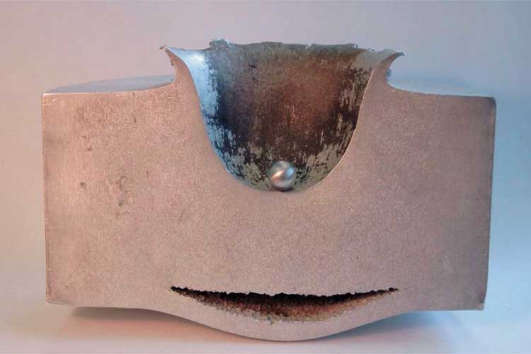
Here, a 1.2 cm Al ball is shot into solid Al at 6.8 km/sec. The Al ball is obliterated of course...the ball shown is for illustration only.


Now imagine what an asteroid of 100x100x100 m can do to earth, at triple that speed...which is the lower limit of asteroid/meteorite speeds...!!!! :o


[Edited on 10-7-2006 by chemoleo]

franklyn - 10-7-2006 at 13:48

Quote:
Originally posted by enhzflep
A method of repeatedly and relatively inexpensively defeating
shaped charge warheads..
Think along the lines of "How do I make a bridge-wire dissapear" ;)

Quote:
Originally posted by nitro-genes
Great stuff! But how about using glass liners?
a PDF hanging around dealing with the concept (see attachment)

I do not see the benefit of this technique over reactive armor applique. The
trend now to have tandem charges impacting in a sequence just results in an
arms spiral. It seems to me money and effort is better spent preventing the
projectile from acting on the armor in the first instance. Israel supossedly has
experimented with a device that produces an electromagnetic pulse as the
munition approaches. This induces sufficient current in the wiring to fire the
detonator. Of course this requires extraordinary timing given the brief window
for effective countermeasure. This also can be countered by a munition using
coaxial wiring and Faraday shielding. A gun fired APDS round is still the most
effective trenchant penetrator, requiring 30 inches of cobham armor to stop,
a reason for the shift in tactic to death from above, 30mm caliber as apposed
to 120mm plus coming from the side.

.

nitro-genes - 19-7-2006 at 09:26

Quote:
Originally posted by chemoleo
Here, a 1.2 cm Al ball is shot into solid Al at 6.8 km/sec. The Al ball is obliterated of course...the ball shown is for illustration only..


More than 11 km/sec with only blackpowder as the propellant...light gas guns are fun! :D They are used by NASA indeed to describe possible meteorite impacts on earth, but they also plan to shoot satellites directly into orbit with much larger designs. :)

The design of such a device doesn't even seem all that complicated at first glance, low detailed schemes can even be found on the internet, with the "breakthrough" valve beeing the most difficult part probably. I wouldn't be surprised if such a thing could be built in a couple of years in a garage. (Make sure though you don't have to explain the neighbours what you are building) That would really be a madscientist project! :D

nitro-genes - 22-7-2006 at 03:16

It turns out that with the semtex-like explosive (160-170 kbar range) I was using, penetration of more than 2,5 times cone diameter is not possible, so the 28 mm copper cone thus was already very close to the limit probably with 5 cm of steel and over 10 cm of soil.

Completely by accident found this graph of the chapman-jouguets detonation pressure versus penetration in PATR. It is a pitty though they don't mention the test setup, liners used, explosives etc...:(


[Edited on 22-7-2006 by nitro-genes]

NBK - 29-7-2006 at 22:12

A question for the esteemed membership that's been stumping me, and that someone here may perhaps be able to answer.

The question is, if you have two seperate plates of metal, say copper, arranged in a configuration like that of a typical shaped charge and touching at the apex, would the plates flow like a typical shaped charge liner into a jet?

Or, would they behave as two seperate entities and collide into each other, in an explosive-weld?

Mind you that these plates are free to move relative to each other, meaning that they're not welded together, only mechanically held together by spring-tension or such, not massive confinement.

I've checked through my copy of FoSC, and other texts, and found no answer. Perhaps someone here has experimented with such liners?

[Edited on 7-30-2006 by NBK]

nitro-genes - 1-8-2006 at 01:49

I don't know what the esteemed and stumping member thinks, but I do have some thoughts...:D

After posting that the liner thickness probably determines the liner element velocity in a great way I was wondering what a thicker liner would do. I decided to use a 1 mm liner, because for a 32 mm diameter charge this would be close to the recommended thickness that is 3% from charge diameter. I had no 1 mm copper plate left, so I took 2 identical 0.5 mm thick, 60 deg. cones and spun them together on the mold until they fitted together perfectly. They still could be seperated from eachother with ease though...

Penetration using this liner was even a little deeper than with the 0.5 mm thick liner. The entry and exit hole were considerably less wide though, probably due to the reduced jet velocity. There was nothing strange about the entry or exit hole btw, so probably it is perfectly ok when the two plates are completely attached...

It would be a problem I guess when there is a space between the two liners. Detonation pressure drops rapidly with increasing distance from the explosive. So with a lot of space in between, the liner touching the explosive would be accelerated to a high speed, while the other one would not move considerably until hit by the accelerated plate. The accelerated plate would "share" its kinetic energy with the other plate releasing a lot of heat from the collision, reducing the perforance of the charge in a great way probably...

Rosco Bodine - 1-8-2006 at 20:29

If my mindreading skills are operating correctly :D

I smell a piano hinge linered linear shaped charge in the works , where the angle may be set where desired and then the pivot soldered to keep it there .

nitro-genes - 2-8-2006 at 01:02

Lol, time to put the tinfoil back on my head again... :D

The idea sounds good. :) I don't think the acceleration of the plates will be affected by the fact that the two plates are connected by a hinge. Even when the two plates would be enterily seperated it shouldn't be a problem I guess.
The force of the detonation pressure exceeds the material strenght by far, so the small amount of resistance in a liner made from one piece would be rather insignificant...

[Edited on 2-8-2006 by nitro-genes]

Marsh - 6-8-2006 at 16:33

Well I browsed this thread a bit and have one remaining question for you guys...

Where exactly do you find copper cones from? Or what are they called specifically so that I may search for them correctly?

Thanks.

Deceitful_Frank - 6-8-2006 at 23:12

You "browsed" the best thread in the history of the internet "a bit"and now you are asking the most lazy-ass question I've heard all day!

Nigh on everything you would need to know to get up and running is contained with in the last 18 pages of this thread so I suggest you browse a bit more...

go read and learn!

[Edited on 7-8-2006 by Deceitful_Frank]

Marsh - 7-8-2006 at 09:33

Quote:
Originally posted by Deceitful_Frank
You "browsed" the best thread in the history of the internet "a bit"and now you are asking the most lazy-ass question I've heard all day!

Nigh on everything you would need to know to get up and running is contained with in the last 18 pages of this thread so I suggest you browse a bit more...

go read and learn!

[Edited on 7-8-2006 by Deceitful_Frank]


Edit: Sorry, scratch my question and stupidity...read my next post please.

[Edited on 8-8-2006 by Marsh]

Marsh - 7-8-2006 at 18:37

Alright, to make up for my question, I will impose an answer which you guys just *might like...

Try doing a search for "small cone burner", "cone burner", "brass holder" etc on Yahoo or Google.

Or, click one of these links for an idea without searching:

http://oilsandincense.com/catalog/cone_holder__brass__-__sma...

http://www.makeincense.com/cb1004.html

If brass is acceptable, I may have struck gold.

The only small problem, is that most of these have vent holes, so I advise you to try and find something without these holes on the cone (I mean the side holes, the middle one will always be there, which isn't nesseccarily a bad thing). Although, from the looks of some of the holes, they may be of minor effect on the jet- judging by their size and placement.

[Edited on 8-8-2006 by Marsh]

Fulmen - 8-8-2006 at 02:57

Hey Marsh, if everybody made penance like you the world would be a beautiful place. You've really given me some ideas :-)

nitro-genes - 8-8-2006 at 05:11

To be honest, I don't think they will work at all, I've tried a lot of these common item liners myself too. :(

After searching for potential liners in every f*cking store in town the last couple of weeks you think you may have found what looks like the perfect liner. So with 4 times cone diameter of penetration in mind you start building the charge...

Unfortunately, the liner is made from brass instead of copper, so 4 CD penetration goes out the window. Instead 3 CD penetration is the maximum achievable now. Also, the liner is a little thinner than planned, so 2 CD's remain. Then you think about the explosive to use with this wonderfull liner. 300+ kilobar explosives are difficult to realise, so you settle on PETN/Pib with 160 kilobars of detonation pressure, reducing the penetration ability further to about half of the maximum, leaving 1 CD penetration. Of course you don't use precision made casings, but some sawed off PVC tubing instead...

Nonetheless, happy as a kid you look at your 4 CD penetrating shaped charge, thinking about the huge amount of damage it is going to do. Finally, the hour nears to unleashe your lethal device of death. You light the fuse, wondering if 5 cm of steel isn't too small a target for such a well made device, and you run like hell. A HUGE explosion, and the ground surrounding the charge has become a wasteland. Seeing this you think there is no doubt that the charge has gone completely through...

Your heart pounding with anticipation to see the hole throught the plate, you look at the plate and discover that there is nothing... nada... not even a f*cking scratch!

WTF has gone wrong?! :P

Brass may look like copper, but it has very different properties. My guess is that the presence of two or more atom sizes in an alloy reduces the ductility and dynamic strength of the material drastically, both very important liner material properties. One possible exception to the rule that alloys are no good is steel. I had some good result with stainless steel hemisperical coffeespoons:

--> https://secure1.getsecure.com.au/~tichum/images/p-coffeespoo...

Another thing is the wall thickness of the liner. For optimum performance the wall thickness should be around 2-5% of the liner thickness, depending on the detonation pressure of the explosive used and the apex angle of the cone. Most of these common-item liners are between 0.2 and 0.5 mm thick at most, since thinner plate means cheaper fabrication. I noticed that these thin walled liners produce shallow and wide penetration holes (if you can even call it penetration) when loaded with a high velocity explosive. Probably due to supersonic or near-supersonic jet formation with little mass involved...

Marsh - 8-8-2006 at 07:11

Quote:
Originally posted by nitro-genes
To be honest, I don't think they will work at all, I've tried a lot of these common item liners myself too. :(


Why did you have to burst my bubble so soon...why!?!?

Well that does stink. I had a good feeling that brass should perform over aluminum, and between copper and steel. I'm really not so sure that it can't be made to do just this truthfully, without seeing so for myself.

I have one of these small incense cones at home as a matter of fact, and pent on the way. I just don't understand really, as the alloy seems quite malleable...?

So I think I will (hopefully be able to) solder this cone to a pipe end, and test it this way.

Nitro-genes, have you just used another brass object, or have you actually used a brass cone specifically like the ones I've pointed out? Something in me still thinks they just might work...unless some cold-hard data can talk me out of it.

nitro-genes - 8-8-2006 at 07:54

Haha, I'm so sorry... :) In fact I have no idea how brass would perform under ideal circumstances. It is a known fact however that most alloys perform not very well. My guess is that it performs even worse than aluminium...

I've tried a piece of a bell and a piece of a toy trumpet as a liner with PETN/Pib, they looked like brass to me. Anyway, both liners resulted in a large surface of the target plate covered with small dimples and craters, no jet formation whatsoever. They were not very precise too, so maybe you have more luck...:)

What is the thickness and diameter of the cone you have at home, if the material is really thin, like the bell and trumpet I used, I'm pretty sure it will not work...

Would be nice to see some results in this tread again however, so please try! :)

[Edited on 8-8-2006 by nitro-genes]

Marsh - 8-8-2006 at 08:51

Well, it is very thin towards the middle, maybe 0.6mm or so. But, at it's tip is is cast thicker. It may perform well until the wider portion, where there is also holes. This is only 25mm or so diameter, a larger cone with the same similarities (which is available above) might fair quite well. Linked is also a diagram showing the actual varying thickness areas in the cone. It looks similar to the design of a HEAT charge if you ask me.

Here are photos:


Marsh - 21-8-2006 at 19:16

I posted this in the Perchlorate compositions thread, but I feel that the info should be listed here dealing with shaped charges, so I am basically making a double-post of it...

I was able to test AP/TCAP/MEKP in a shaped charge today, 85:7:8 ratio.

What may be useful here is to note the munroe forces demonstrated from this mixture.

The cylindrical lined charges previously tested by Axt had me interested. It appeared to me by the photos in this thread that the exits were roughly the result of a combination of transferred munroe force/minimal (low mass) jet formation.

It just really didn't look like an efficient jet was formed by the cylindrical-lined charges. This was also mentioned, stating it may have been a hole-punch effect.

My experiment compared to the previous in the respect that I used 16mm diameter copper tubing (vs aluminum), and that my tube length was just slightly shorter; 57mm vs 65mm.

I felt that the minimal liner tube length I gave up (8mm) was acceptable as it helped achieve more head-height above the tube for a flatter shock wave, and my cup container was less than optimal for mass conservation.

I felt that the L/D ratio of the tube should have still permitted a decent jet to form (if one was going to do so), so I too used zero-standoff. I also did this to give an idea of close munroe forces generated from the AP/TCAP/MEKP mixture.

Like always, I used a plastic drink cup. The copper tube was glued to the base, and the cup was packed.

This time around, I really wanted decent head height above the liner, and a whole 465g total was used to fill the cup mostly to allow this. I could have used much less had I used PVC pipe as the container. This is a large amount of explosive, but of coarse the amount which contributed to the jet should have roughly been in the 270-300g range. It was again initiated by one of my weak TCAP dets.

The charge was detonated and the results achieved were not impressive of the design, although it did confirm my assumption that cylindrical-lined charges are not effective at sufficient penetration through thick targets.

Munroe forces bent the total 2.25" of steel all the way through, but unfortunately cylindrical liners do appear to give limited jet formation, and allowed a maximum of about 17mm actual jet penetration.

However by munroe force comparison, it is seemingly apparent that the mixture rivals ANNMSA and would be suitable for shaped charges.

On the back of the first plate, I could actually see a pinpoint (actually about 2mm) of copper which penetrated completely, only to be stopped by the second plate. Thus it is shown jet formation was minimal and/or low mass.

I have pictured todays crater viewable against the other crater made by using a plastic cone from a few days back. I explain its design in the perchlorate thread. What I see is interesting, the jet formation (or cavity shape) seems to play a big role in penetrated material displaced, almost of equal value to that of the liner material chosen (but then again this may seem like a given). The plastic cone charge actually removed almost the same mass of steel it would appear, but with not as deep a penetration.

I have no doubt that if only one plate was used, damage would have occured duplicating the 1" plate test with 16mm tube which Axt performed using the ANNMSA.

Here are the photos:

16mm Cylindrical charge vs. Plastic cone charge crater


2.25" Bent steel


Penetration w/ carrot


Back of first 3/4" plate


[Edited on 22-8-2006 by Marsh]

Marsh - 24-8-2006 at 09:21

In addition to my post above (since I cannot edit now), I had a misunderstanding of munroe forces.

I was calling the actual close-proximity shockwave effect onto the steel the munroe effect, when in actuality this is not what munroe forces are; rather they are result of a gas jet wave from using no liner at all with a cavity.

Still though, interesting jet penetration for a charge which seems there is a lot to be learned about for perfection.

Also for those who haven't correlated this mixture I speak of to the info discussed in the Perchlorate thread, I know Vod's in an AP (ammonium perchlorate) mixture can reach over 7000m/s, but I assume this mixture to be between 5500-6500m/s. This is just an estimate based upon mixture and density, no cold-hard evidence really suggests if this Vod range might be correct.

[Edited on 24-8-2006 by Marsh]

Chris The Great - 27-8-2006 at 21:25

The steel is just bent from the pressure on the detonation wave. The detonation shockwave does travel a short distance outwards from the explosive, although it drops off very quickly. Nothing to do with gas of any sort.

The munroe effect is involves gas formed with an unlined cone hitting and penetrating metal, but will not bend and spall steel, or create the bending you see with your steel target.

It's definately interesting to see that the penetration really is very short, as Axt thought it might be. So your test was quite useful IMO.

Marsh - 28-8-2006 at 15:18

Quote:
Originally posted by Chris The Great
The steel is just bent from the pressure on the detonation wave. The detonation shockwave does travel a short distance outwards from the explosive, although it drops off very quickly. Nothing to do with gas of any sort.

The munroe effect is involves gas formed with an unlined cone hitting and penetrating metal, but will not bend and spall steel, or create the bending you see with your steel target.

It's definately interesting to see that the penetration really is very short, as Axt thought it might be. So your test was quite useful IMO.


Exactly correct, that's why I needed to re-explain myself afterwards, my understanding was a little off.

But, I do have some very useful information to offer as far as obtaining a proper liner, besides what Nitro-genes has demonstrated on producing copper cones from spinning. In fact I feel it is the most proper liner available that has been mentioned yet...

The funny thing is that this item is probably surrounding most of us at nearby plumbing stores.

Please checkout this link (this is a wholesaler though, not a retailer): http://www.customtee.com/ends.htm

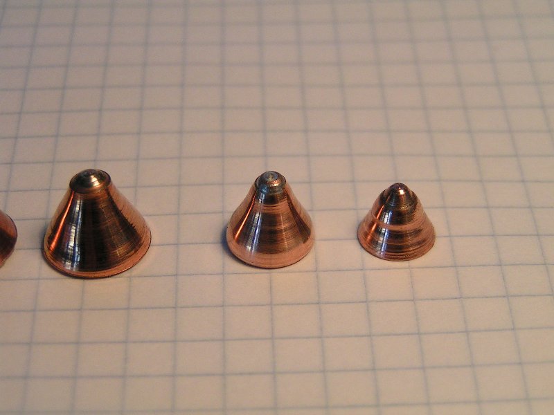
These are spun copper endcaps for termination plumbing (which are cut before the sinks etc are installed in new homes). I called this specific manufacturer today and found out the following info: The smaller sizes (1" diameter) will have more of a pointy cone at a lesser degree (like the second photo on that page), while the larger 1.5-2" diameter will have a cone which looks like this:


I found local retailers by contacting a wholesaler near me on the list which is linked at the bottom of their page I provided, and then they were able to tell me the retailers they supply to.

My local plumbing shop indeed has them, and I will be picking up 1.25" and 2" diameter sizes tomorrow. As was pointed out, for a 3% thickness of cone diameter, and assuming 1mm walls, 1.25" should be closest to optimal.

What's excellent here is the fact that these can be cut down so that needed standoff is included attached to the cone.

Mnky - 2-10-2006 at 12:25

I think PLX is 5% of 99%HNO3 and 95%Nitromethane?
Or does 65%HNO3 work for PLX?
Do i need HMTD to explode PLX?

Sorry for my bad english:P

Greets from Switzerland ;)

Quince - 2-10-2006 at 19:20

LOL!

Deceitful_Frank - 2-10-2006 at 23:03

Quote:
Originally posted by Mnky
I think PLX is 5% of 99%HNO3 and 95%Nitromethane?
Or does 65%HNO3 work for PLX?
Do i need HMTD to explode PLX?

Sorry for my bad english:P

Greets from Switzerland ;)


Your bad english shouldn't necessarily be a problem so long as you are actually making an effort, not simply asking to be spoonfed and atleast posting in an appropriate topic!

You should delete your post, do some research and return in a more appropriate thread. I have some knowledge of Picatinny liquid explosive and would be happy to help any pyro that shows evidence of helping himself

Disregard the "village idiot" of Science Madness. Do you think he wonders what life would have been like had he received enough oxygen at birth... I will also delete my post when it has served its purpose though as for him removing his "contribution", I wouldn't hold my breath.

nitro-genes - 9-10-2006 at 03:18

Recently I tried one of the eutectic compositions mentioned by Boomer in the "Perchlorate compositions" thread...

1 part of AN, UN, HDN and NaN were finely ground and heated together at 90 deg until it was of a runny consistancy. The heat was then removed and the mixture was allowed to cool down to 80 deg. C. after which 20% of PETN was added. This to reduce the large failure diameter for these compositions. Upon cooling further to about 50 deg. C. the mixture became like a thick paste, that was cool enough to be loaded into the container by hand. After loading, the charge was put into the fridge for a couple of hours which turned the composition into a rock hard material. About 10 grams of PETN/Pib was pressed on top of this as a booster and the whole charge was fired against the side of the same block of steel that I had been using for the other charges.

The picture on the right shows the entry hole of the eutectic loaded SC...


Strangely, the entry hole of the eutectic looks much different compared to PETN/Pib. Much less "tidy" so to say, and without the funnel shape that quickly narrows down to the main jet channel like with the other two charges. The channal itself doesn't look as smooth as with PETN/Pib and contains a lot of irregular ring shapes. The density homogenity is possibly somewhat less then with other plastiques and this could be the reason for the imperfect focus. Like with the PETN/NG charge...
The penetration however was not bad at all, certainly not for a composition containing only 20% PETN. The failure diameter of this compostion should be >1 cm, so compared to the 2-3 mm of PETN/Pib plastique I expect that the performance could even be drastically improved for larger charges. Pour loading and fast cooling would also be much better, since the thick past I used contain a lot of precipitated AN probably. While the brisance of these compositions comes from the principle that he fuel and oxidizer are so intimately mixed together that it behaves as an ideal explosive. Unfortuantely, pouring proved difficult, because as soon as the mixture touches the conductive copper liner it becomes solid, resulting the incorporation of many voids at the base of the liner. Next time I will pour the charge, using a waterbath to heat the explosives container, and cool it down quickly...

[Edited on 9-10-2006 by nitro-genes]

franklyn - 29-10-2006 at 07:45

This is an update on what I had mentioned here before
about an Israeli EM device to detonate RPG's some
distance away from the vehicle thus protected _
http://www.sciencemadness.org/talk/viewthread.php?tid=2219&a...

Cats out of the bag now it seems, see for yourself _
http://www.youtube.com/watch?v=ARM-Alwot3I

[Edited on 29-10-2006 by franklyn]

nitro-genes - 29-10-2006 at 15:10

Amazing shit! :o

Do you have any clue about how it works? Nothing is said about it in the videoclip unfortunately... (maybe top secret has got anything to do with that :P)

A continuous EM forcefield strong enough to demolish a rocket would require tremendous amounts of energy, so it is probably some active defence system. Most AP RPG's are piezo initiated so it could be that enough current is produced by the rocket passing through the magnetic field that the initiator fires. From the video though it looks like it really hits a solid wall...:o

franklyn - 29-10-2006 at 18:57

Quote:
Originally posted by nitro-genes
Most AP RPG's are piezo initiated so it could be that enough current is produced
by the rocket passing through the magnetic field that the initiator fires.
Exactly
Piezo crytals merely laying out exposed to heating by sunlight are strained such
that by merely casting a shadow on them will in many cases produce the current
sufficient to fire the initiating detonator, providing the arming cicuit is closed.
Induction produced by the motion of the missile itself through a pulsed field
also contributes to the eddy current.
It happens that mechanical fuzing has to be precision made and requires
additional safeties that make's using a particular munition more cumbersome and
less reliable in the hectic enviornment of infantry operations. This is not a
problem for air ordnance where there is always time to prepare and rearm a
fighter. For this reason all modern anti tank munitions are electrically fuzed, it
also permits very accurate firing for optimal placement of the explosive effect.
Destroying any elctrical components makes it a dud.
I can imagine a tank echelon equipped with an advanced system of this type
could conceivably counteract any overhead attack from "smart munitions".
by having many tanks acting as a unit they are all defended much as large
bomber formations in WWII could fend off fighters with concentrated firepower.

There is a thread here on pulsed power devices _
http://www.sciencemadness.org/talk/viewthread.php?tid=6032

[Edited on 30-10-2006 by franklyn]

a_bab - 1-11-2006 at 09:45

Actually, it works by defeating the RPG with a "counterprojectile" (or rather a cloud of projectiles) and not by some kind of forcefield. The protected area could be imagined though like a shield around the tank.

This involves high precision radars, cameras, target locking devices, etc. More to read here: http://www.defense-update.com/products/t/trophy.htm

franklyn - 3-11-2006 at 23:53

Quote:
Originally posted by a_bab
Actually, it works by defeating the RPG with a "counterprojectile" (or rather a cloud of projectiles) and not by some kind of forcefield.

On closer inspection of the cited video link here _
http://www.youtube.com/watch?v=ARM-Alwot3I
One can see in the first 2 intercepts some kind of fragments or projectiles
moving opposite to the missile. In this next link citing the "Trophy" system
http://www.defense-update.com/products/t/trophy.htm
Quote:
[color=darkred]" Specific details about the composition and mechanism of this explosive
interceptor device are vague. From the briefing provided by US sources,
Defense Update understands that Trophy is design to form a "beam" of
fragments, which will intercept any incoming HEAT threat, including RPG
rockets at a range of 10 – 30 meters from the protected platform. "[/color]

So this employs a shotgun approach to anti missile defense, and here I
thought this was cutting edge. Seems now it's nothing more than a small
version of the C.I.W.S. (close in weapon system) radar aimed 20mm
gattling gun placed on board naval ships to fend off anti ship missiles.
Quote:
[color=darkred]" The Threat Detection and Warning subsystem consists of several sensors,
including flat-panel radars, placed at strategic locations around the protected
vehicle, to provide full hemispherical coverage. Once an incoming threat is
detected identified and verified, the Countermeasure Assembly is opened, the
countermeasure device is positioned in the direction where it can effectively
intercept the threat. Then, it is launched automatically into a ballistic trajectory
to intercept the incoming threat at a relatively long distance. "[/color]

The description in the review cited does not however provide much insight
to how it can do what it claims here,
Quote:
[color=darkred]" The system can simultaneously engage several threats, arriving from different
directions, is effective on stationary or moving platforms, and is effective
against short and long range threats (such as RPGs and ATGM). "[/color]

While I fully concede I misidentified the mode of action of this device, it is
not however the only candidate for active protection, from the same source
there is also this item somewhat more in keeping with what I have in mind.
Quote:
[color=darkred]" defense consists of directional, laser-assisted electric pulsed effect.
The system uses UV laser which ionizes the air to enable effective
conduction of the electrical pulse to a range of up to 30 - 100 meters.
The pulse will disrupt the electronic elements of the incoming missile
and could also trigger it to explode immaturely."[/color]
http://www.defense-update.com/products/x/xads-aps.htm

[Edited on 4-11-2006 by franklyn]

nitro-genes - 7-11-2006 at 05:08

Hehe, for a moment there I thought startrek had become oldfashioned! ;)

The counter projectiles are likely to be fired by the "metal storm" principle, which can produce a beam or cloud of projectiles. Since the metal storm system contains no moving parts it is probably the only thing fast enough to react in the small timeframe given during an RPG attack. The response time of the radar and targetting systems must be incredibly fast. it is hard to believe it is fast enough to counter high velocity recoilless weapon projectiles from close range...

http://www.youtube.com/watch?v=Ih2vPGMQzlo

Axt - 16-1-2007 at 21:06

Quote:
Originally posted by Axt
Though there is the book, "Evaluation of Improvised Shaped Charges" search amazon for it, still available on special order. Essentially the book is a reprint of a study on cylindrical lined charges. Its just a heap of tables with charge dimensions, materials and penetrations. I cant remember much from it, only that a short standoff was desirable ~1/4" or something. I had it opened it once, then lost it :( It was for Al/steel/Cu tubes but unsure what explosive was used, C4 or equivalent plastic explosive I think.


Found it and scanned it. Beng a "desert publications" book, the source of its information isn't given but in the text it is mentioned that its the original study of improvised cylindrical liners to determine the best dimensions to be used in the army training manual "TM 31-210 Improvised Munitions Handbook" and indeed it is in there on pg 87. See attachment.

Attachment: Evaluation of Improvised Shaped Charges.pdf (1MB)
This file has been downloaded 1996 times


pyrotekniker - 17-1-2007 at 14:47

Hello

I've been reading about shaped charges, and decided to try it. I've done some tests using NM/HNO3 and found that this is the explosive I want to use.

As a linear I found this:
Copper Linear

I know the quality sucks, but you can at least see the shape. It's about 5cm across at the bottom,
and has a hole in the middle at the top which has a diametere of about 1cm.

Could it be used?
I think I have to build the charge the way that Axt's glass linear charge is built.

Boomer - 22-1-2007 at 03:58

Adobe tells me the book-pdf is damaged.

The cone could be used, but why start so big? You'll need at least half a pound HE.
How thick are the walls? How will you protect it from the nitric? Not funny having it start boilling before you're finished.

pyrotekniker - 22-1-2007 at 06:29

Have no plans of beginning with that one :o Going to try smaller ones with cartridges and hollow bullets.

I just found it, and saw that it had the right shape and thought; why not? Probably going to cover the walls with some plastics. The walls are probably 2mm or something.

nitro-genes - 1-2-2007 at 12:06

Waveshapers can save a lot of explosive, as well as give better performance. Alligning it into the charge container however is very difficult to do precise enough to function well. Military charges use the planewave generator a lot, which is an upside down coneshaped waveshaper that creates a plain detonation wave even with small headheight...

So I thought of a simple way (admittedly, pure genious :D) to make this and allign it easily inside the charge.

First you press in the PBX after which you press hard onto it with a dowel having a cone shaped end. This will leave a cone shaped cavity. Then you make sure the charge is level, and pour in some epoxy resin, leaving at least 2 times critical diameter at the sides. Then press some PBX on top...

By varying the slope of the cone you can alter the effect, large angles produce converging detonation waves, while smaller angles produce a plain detonation wave...

I tested a 32 mm charge this way, with 20-25 grams of 85/15 PETN/Pib at 1.5 g/cc, 210 kbar, critical diameter of 0.7-1 mm. (Thanks to HMTD! ;)) It penetrated the entire side of the steel block, which was 12 cm, and another 3 cm into the ground...

[Edited on by nitro-genes]

Making a planar wave generator (waveshaper) 2.GIF - 13kB

gnitseretni - 1-2-2007 at 19:41

An idea just popped up. Make (or have them made) a cast iron male and female mold of a cone with a metal bolt inside and sticking out a little and weld them to a vice. Then place a sheet of copper in between the molds and "press" as many liners as you need. What do you think?

nitro-genes - 2-2-2007 at 19:04

Pressing is not as easy as it may look. When you want to press a cone shape out of soft copper sheet in one press you will tear through the metal for sure. In order to do so you would need to make a series of pressing molds, going from a very blunt apex in the beginning and more cone shaped for the last pressings. There is a los alamos report on how to do this with the punch and die technique, though making al the different pressing molds would be a quite a job. Hemispherical liners would be the best option for pressing, though still it is difficult to get a liner with a constant wallthickness this way. The coppersheet can have problems sliding in the mold smoothly, resulting in one side beeing more streched and thus thinner than the other. You would need to polish and lubricate the mold well in order to prevent this...

I've uploaded the movieclip of the charge with the waveshaper, I hope this extra MB of space isn't a problem, else let me know...

The charge was recorded from a larger distance this time to capture the jet spray consisting of copper beeing thrown out of the formed jethole better. It is in essence very anologous to the effect when you spray a stream of water into a mudbank, in which the excess water traveles along the sides of the formed channel in the opposite direction of the stream itself. It goes at least 4 meters in the air judging from the movieclip. :)

[Edited on 3-2-2007 by nitro-genes]

Attachment: 32 mm charge 85% EF PETN-15% Pib at 1.50-1.53 density + plastic waveshaper compressed.avi (959kB)
This file has been downloaded 1953 times


gnitseretni - 3-2-2007 at 09:13

as long as it doesn't tear and the little wallthickness variation that may occur here and there doesn't affect the performance of the shaped charge too much, than I could live with it :D

nitro-genes - 3-2-2007 at 09:34

An equidimensional wallthickness is the most important feature of the liner that determines the performance, especially for cone shaped liners that are much more sensitive for variations in symmetry than hemispherical ones. So both for pressing as for performance I would recommend using hemispherical liners first. There is a slight performance decrease for hemispherical liners, but this is mainly because of the pole region disrupting the formation of the jet. Hemispherical liners with a hole 25% of the liner diameter in the pole region are said to have much higher jettip velocities and can perform as well as cone shaped liners...

gnitseretni - 3-2-2007 at 12:42

Thanks for the info Nitro. I still have much to learn. I actually thought I had a good idea there though :(

mfilip62 - 15-2-2007 at 05:56

Nitro,are you saying that hemispheric liner with hole in it would be better?!?!

How thick (for exp. Cu liner) shuld bee!? Why?
Is ti true,that (conical) liner should bee;"As thin as posible!"

[Edited on 15-2-2007 by mfilip62]

nitro-genes - 15-2-2007 at 19:33

Yes, though use of explosive lenses (an inert rod from center of liner up to the detonator for example) could give the same performance. Supposedly they give higher jettip velocities...

Thickness depends on the liner diameter, apex angle, and detonation pressure of your explosive, usually 2-3% of the liner diameter for copper though in combination with a brisant explosive like plasticized PETN, RDX, cast TNT etc...

nitro-genes - 27-2-2007 at 07:20

I selected some nice video demonstrations of the shaped charge, the squashead principle and the EFP. The shaped charge demonstration is accompanied by Manfred Held, inventor of the explosive reactive armour and an authority in this research field. :)

Shaped charge and squashead:

http://rapidshare.com/files/18536608/New_WinZip_File.zip.htm...

EFP:

http://rapidshare.com/files/18549805/New_WinZip_File_2.zip.h...

PS: Don't know how long the links will be available since their probably a copyright violation. ;)

quicksilver - 27-2-2007 at 07:52

This whole thread is great. It would be very nice to extract this whole thread and make a pdf from the material. The information disseminated is quite vast and the thing actually could be expanded to encompass the embedded stuff as well.
- =-= I hate having to wait a day w/ rapidshare. The first avi was good & wanting to see the next one makes it so I have to keep a reminder to snag it or else rapidshare will zonk it soon =-=--:o

nitro-genes - 27-2-2007 at 08:18

The PDF idea is a good one, it would be a lot of work though to extract all the usefull information from this huge thread. I've made a start in making a detailed description of how to produce spunformed liners, the charge itself, waveshapers and the synth of several highperformance plastiques and castable mixtures to be used with these liners. I am willing to make a start with writing such an exerpt from this whole thread and other resources, if noone objects against I'm doing so because a lot of the information was provided by others like Axt, NBK, Boomer and HMTD by U2U... :)

Sorry for the double download btw, somehow I got an error when I attempted to upload them all together in one zip...:)

[Edited on 27-2-2007 by nitro-genes]

MRUD - 28-2-2007 at 11:46

This is my first post, and sorry, english isn't my native language.

I've seen the video nitro-genes posted, and now im wondering.
The man in the shaped charge part said, the con diameter was about 65mm and the standoff at 120 mm, thats nearly 4 times of con diameter.
But everywere i read something about chaped charges, it's written that the standoff schould be equals the con diameter.

Are there some other things i didn't now about that problem, or i'm totally wrong?

I would be pleased, if you can help me finding out.

MRUD

Microtek - 28-2-2007 at 14:47

Hmm, 120 mm is actually only about two times the cone diameter of 65 mm. Anyway, you can use a variety of standoff distances; what's optimal depends on cone angle and charge geometry.

nitro-genes - 28-2-2007 at 15:23

They used 250 mm standoff, so little under 4 times cone diameters indeed. This is because the penetration is mainly determined by the lenght of the jet at the time it hits the target. Longer standoffs give the jet more time to stretch longer and thinner than for shorter standoffs. As a result the penetration is deeper, but also less wide. The problem is that the longer and thinner the jet stretches, the more sensitive it will become to flaws in the liner symmetry, allignment of the charge and liner etc. Professional shaped charges, like used in warheads, actually have an optimum penetration depth at about 6-8 charge diameters. An improvised shaped charge isn't constructed precise enough to able to stretch to such lengths before the jet dissintegrates, so in this case more than 2 cone diameters is about the limit. The standoff also dependends on the shape of the liner, like the apex angle of the cone. EFP liners of 140 deg need as much as 10-20 cone diameter standoff, while cylindrical liners (0 deg) are optimal at 0 CD standoff. Hemispherical liners also need a somewhat larger standoff. The purpose of the charge is also a factor, some demolition charges don't need long and thin penetrations in steel, so they are deliberately used at smaller standoffs to produce less deep, but wider penetration holes since their momentum will be about the same...

The charge used in the video should have been used at smaller standoff as well, since the jet clearly seperates into two independant parts as the penetration progresses, and the entrance hole is surrounded by dimples. Shows how sensitive the formation of the jet is for imperfections in the charge. I've had the same phenomena on several occasions as well, I wonder what determines this odd behaviour. :)
The last charge with the waveshaper, from which I posted the video, used 3.5 times standoff which is about the limit with these spunformed liners, since I tried several smaller charges before with 4 CD standoff that showed a very messy entrance and reduced penetration. Then again, maybe it was just a lucky shot, since the penetration was really perfect, with a smooth and straight penetration channel...:)

[Edited on 28-2-2007 by nitro-genes]

shapedch.jpg - 40kB

nitro-genes - 28-2-2007 at 16:47

Ok, just to show what a real shaped charge should look like (and some people wanted to see the pictures) I've made effort to take some pictures of the results of the charge with waveshaper. :D

The first thing that is striking is the opening width of the entrance, that is only about 10 mm. This is clearly the result of the increased standoff, since the other charges, fired at 2 CD standoff had a much wider entrance diameter of 22 and 17 mm respectively. Proof to the increased stretching of the jet at longer standoffs.

The other thing that is obvious is the "cleaness" of the penetration, no dimples are visible surrounding the entrance and the entrance hole itself would have been perfectly round if it were not for the off-center carrot that hit the side of the entrance hole. (left of the entrance in the first picture) It was better visible right after the charge was fired, since there was some coppersmear at that spot. Rusting of the block has made that it is not very clearly visible anymore. Just an observation, but I noticed that the areas on the steel that have been subjected to high pressures somehow rust much faster on storage, maybe due to microfracturing...:)

The remnants of the 30 mm grey PVC standoff tubing can be seen as grey circles on the block as well...

Due to the fact that I had little space left on the steel block for another penetration (:D) I had to put it pretty near one of the holes on the corner of the block. The sideway displacement of the steel ruptered the steel into an opening about 5 cm after the entrance, which gave a perfect opportunity to lighten and thus photograph the inside of the penetration channel. This rupture can be seen on the photo on the right, at the top of the picture on the right...

Unfortunately, you can't look entirely through the channel since about 3 cm before the end there is some piece of the liner/carrot obstructing. Maybe because I used a more trumpet shaped liner, I noticed these trumpets produce much narrower carrots than straight liners, and this could possibly be another reason why it is used in HEAT rounds, the carrots are narrow enough to enter the tank through the jet channel and cause secondary effects inside the tank...

[Edited on 1-3-2007 by nitro-genes]

32 mm shaped charge + waveshaper penetration.jpg - 112kB

12AX7 - 28-2-2007 at 17:53

Possibly electrolytic reaction with the copper "carrot" / spray?

Tim

nitro-genes - 28-2-2007 at 18:37

Think so, Fe3+ can displace copper easily, a friend of mine used strong FeCl3 solutions to develop his own circuitboards. The plugsmear is gone on all the other charges as well. Could just be the volume of the rust though, someone told me that 1 mm of steel forms about 1 cm of rust! :o

MRUD - 1-3-2007 at 10:43

Ohh, sorry for that mistake "what the hell was i thinking, while typing 120mm" shure, i meant 250mm.

And by the way, tanks for your good explanation and graph nitro-genes.

MRUD

MRUD - 3-3-2007 at 13:48

Thanks to all posters in this thread.

Whith your help and the many good explainations i managed to set off my first shaped charge, wo was able to penetrate 1cm of steal.

Thanks

1
2
3

kiknet - 7-3-2007 at 07:08

I think thats a good effort for a first Shaped Charge, what were the specifications of it?

MRUD - 7-3-2007 at 09:23

Specification as listed:

Diameter of con: 30mm
High: 35mm
Standoff ~32mm

Charge: 30g PETN initiated with 1g HMTD

Con was made from copperplate 1mm thick by cutting out and forming it.

mfilip62 - 24-4-2007 at 11:08

Are shaped charges good for digging up holes in the ground about 1-2m deep!(wine bottle SC for example)

My idea is to dig one crater(0,5-1m width,1,5-2m deep) with some explosive,but i cann not digg the hole for placeing it.
Ground is too hard and contains a lot of rocks.

(Please dont ask me what for do I need a hole;nothing special,I did not kill anybodye!:D)

Thanks

nitro-genes - 1-5-2007 at 17:49

Quote:
Originally posted by mfilip62
Is it true,that (conical) liner should bee;"As thin as posible!"


That is an interesting question for which I've found no indiscriminate answer thus far. FoSC states that the liner thickness should be between 2 and 6% of the charge diameter and further states that the optimal thickness is different for every setup, liner angle, explosive used etc...

In general, the thinner the liner the faster the liner wall velocity and jettip velocity become. (see attached picture) Until the linerwall velocity hits the sonic criterium of about 1.2 times the speed of sound of the liner material used, in which case no jet is formed. The thickness for which it reaches this point depend on the detonation pressure of the explosive and the cone angle of the liner. This is probably why explosives with high detonation pressures can perform so much better, they can be pretty close to the sonic criterium with a thicker liner than less brisant explosives can, which means more extruded mass with the same speed, which in turn means better streching (jet lenght) and more kinetic energy. I've seen some programs and publications about how to maximize jettip velocities, so apparently this is indeed a key factor for optimal penetration. From what I can understand there is a correlation between jettip velocity and the jet length (penetration depth), probably the increased velocity gradient aids in better jet stretching. Such charges that are close to the sonic criterium during liner collapse are called "extreme" but put contraints on the precision of the charge in order to function well. The mass extruded from a thin liner is less of course then that of a thicker liner so is bound to be more sensitive to early particulation due to errors in the charge or liner. From my own experience with spun formed liner I have found that a liner thickness of 1.2% of charge diameter was about the limit for a semtex like explosive with 180-190 kbar, but gave less penetration than 2.5-3%. I couldn't go much lower than that while keeping the charge diameter small at 30 mm, as spinning of copperplate thinner than 0.5 mm is almost impossible to do without tearing the metal...

Anyway, it is absolutely impossible to optimize the liner thickness of your improvised SC as an amateur. There are so many factors at work here needing the whole shockwave dynamics/hydrocode mathematics to describe materials under these pressures, liner angle and precision, gurney energy/detonation pressure of the explosive, acceleration time of the liner wall, grain texture and orientation of the copper, etc, not even talking about waveshapers. The programs used to solve such complex problems need a lot more cpu power than the avarage PC unfortunately...

[Edited on by nitro-genes]

[Edited on by nitro-genes]

[Edited on by nitro-genes]

Liner thickness and jettip velocity.JPG - 12kB

Microtek - 2-5-2007 at 13:33

Nitro-genes: When you spin your liners, how small can you make the non-conical part at the apex? I have been able to get down to around a 3 mm hemispherical apex, but this is fairly large considering that my charges are only 10 mm in diameter (no sub-calibration). I'm still experimenting to improve my spinning skills (it's quite a lot of fun anyway) so any pointers you have would be greatly appreciated.

I got quite good results from laminated copper foil (19 mm into mild steel from 1.6 g pressed PETN using a very simple but precisely machined 9.65 mm charge) but a spun formed liner is so much more elegant. And also more durable.

My third shaped charge

Deceitful_Frank - 2-5-2007 at 13:47

240 grams (approx 133ml) of 96% sulphuric acid was placed into a 600ml borosilicate beaker and using a bath of iced water, chilled to 5 celcius.

Meanwhile, 80.07 grams of ammonium nitrate was ground to a fine consistancy and sifted to an even, light free-flowing powder using a regular kitchen flour sieve. A similar grain size to caster sugar was achieved.

20.03 grams of erythritol was also ground by hand in a pestle and mortar to a mesh size resembling icing sugar.

When the acid was sufficiently cold, the nitrate was added in portions beginning at around 5 grams but quickly increasing to around ten grams at a time. The temperature was closely watched and allowed to rise to around 25 celcius to aid fast dissolution of the nitrate, stirring was rapid and even of course.

When completed the nitration bath was again cooled to around 5 celcius before the addition of the erythritol.

The erythritol was added at a rate of around a gram at a time to begin, increasing to maybe 2 grams at a time until 15 of the 20 grams had been added. Making sure that with each addition, all remaining erythritol had already gone into solution.

After 15 grams had been added the consistancy of the mix had become so thick that smaller and more careful additions became necessary. I feel that this is one area of the synthesis where care, good consistant stirring and concentration can really improve yeild. After some 25 minutes all of the erythritol had been added, the temperature had settled at around 16 celcius and the mix resembled beige toothpaste.

The whole deal was then stirred thoroughly and placed in a bath of luke warm water to raise the temperature to 25 celcius, removed from this bath and allowed to stand at room temperature for 30 minutes. After this time the mix's consistancy had thined a little to smooth porridge and could then be poured into one litre of iced water with yet more rapid stirring.

The 600ml nitration beaker was then rinced out with more cold water, added to the rest and the whole lot was made up to around EIGHT litres in a clean polythene waste paper bin.

After allowing an hour for the fine seddiment to settle to the bottom of the bin it was all decanted through and then filtered with three large coffee filters and allowed to dry for a day at room temperature over a pile of old newspapers.

This gave approximately 32 grams of near dry crude ETN. I am guessing that residual acid in my crude ETN would have prevented it from drying any more than into a soft clumpy powder... and so on to recrystalization.

One clean 454g jam jar was selected and into it went the near-dry crude ETN and 120ml (110ml would have been enough for this lab) of mineralized (containing gasoline) pink methylated spirit. The lid wa sealed and the whole deal was held under the hot kitchen tap at 55 celcius to heat the meths and dissolve most of the ETN. A large pan of water was then heated to 60 celsius, removed from the heat and the sealed jar was then placed into the pan, partially submerged and left to cool overnight.

The result after filtering and drying was 22.07 grams (46% yeild... can definitely be improved) of beautiful beige crystals that appeared to take the form of short thick needles maybe four times as long as they were thick. These crystals tended to clump together in groups of half a dozen or so. I suppose the powder wasn't exactly free flowing but needed tipping to around 60 degrees before movement was observed. The bulk density of this purified ETN was around 0.9 so not quite high enough for making decent plastique. I did toy with the idea of setting aside 25% and instantly precipitating from acetone crashing into water to obtain ultra fine ETN to add back to the original sample and fill in some of those gaps... Definitely on my to-do list.

Speaking of those gaps, I decided to try filling them with nitrated liquid polyol. A 50:50 mix of EG and glycerol was nitrated to give a blasting oil that benifited from the ease of manufacture and resistance to LVD of EGDN but with the high density and yeild plus lack of vapour pressure of NG... a most excellent mix!

The composition of the main charge was 44% ETN, 36% EGDN/NG and just for kicks I thew in 20% 600 mesh german flake Al. I knew that this would lower the brisance slightly but I have long since wanted to try aluminized explosives and everyone loves a BIG bang :P

Right.... thats enough for tonight... to be continued.... again!


[Edited on by Deceitful_Frank]

untitled.bmp - 960kB

nitro-genes - 2-5-2007 at 15:18

Great video Frank, your director skills are obviously much better than mine, hopefully pictures and more about the charge setup and result will follow. :D

Offtopic: What does the crystal shape of ETN look like when recrystallized this way?

Quote:
Originally posted by Microtek
Nitro-genes: When you spin your liners, how small can you make the non-conical part at the apex?


I found a trick to make the cones as pointy as you want, even for liners as small as 15 mm diameter. I'm going to include a very detailled description of how to produce good liners by spinning as there are some more helpfull things that I hadn't mentioned so far. I must say however that I noticed no performance drop for liners having a large hemispherical part, in fact they seem to be somewhat more tolerant in jet formation towards errors in symmetry and explosive homogenity.

For making the hemispherical part as small as possible:

First spin the liner until it is firmly attached to the mandrel. Then anneal the copper again and remove the contramandrel holding the liner against the mandrel. This allows you to work on the tip with the working tool. It is difficult to describe precisely how to extend the hemisperical part into a pointy cone, but it is important that you make rowing sweeps from the base of the hemispherical part of the cone towards the tip with a large amount of pressure. The liner may become detached from the mandrel, rotating only on a part of the mandrel but this is normal.

When the tip of the cone is finished, clamp it very softly (else you will crush the tip of the cone!) again with the contra-mandrel and make some sweeps over the entire liner to make sure it is perfectly symmetrical after working on the tip. Then it is very important to anneal the liner one more time to remove any stresses in the metal that can disrupt jet formation, like the after annealing in the los alamos report. Then I usually take a cutting tool to remove some of the base of the liner to make the base perfectly level after which I apply gentle pressure on the liner surface with some fine grained sanding paper (600), and later steel wool to finish the surface. This removes any specks of copperoxide from annealing that you press into the surface of the liner with the working tool. It is best to remove all oxide with some HCl after each annealing, but usually I'm lazy and just use sanding paper and steelwool to remove the oxide dimpels from the liner surface while it spins in the lathe.

I've found a nice way to remove the oxide from the inside of the cone as well. :) Take a thin strand of steelwool and put it between mandrel and liner, while you press the liner against the mandrel by hand. (with the strand of steelwool in between) This does sand down the mandrel as well but it can be reshaped very fast with a large straight blade chisel. (Take care not to touch the spinning mandrel with the chisel while it spins towards the chisel blade, it tends to ruin your mandrel and make your chisel stick into the ceiling ;))

This may sound like a lot of work, but it actually takes about 15 minutes at most for every liner with all the tools ready, especially small liners of 15-17 mm can be produced very fast and consistent...

The result should look something like this, 15 mm diameter, 0.5 mm thick copper and an apex angle of about 55 degrees. I've made better ones btw, but this one was the only one I had left for that same reason. They pierce little over 5 cm's of steel in combination with extra fine PETN + 15% PIB @ around 210 kbar, 2.5 CD standoff and a charge diameter of 16 mm ID and 17 mm OD (PVC adapter for 5/8 inch PVC tubing)...

[Edited on by nitro-genes]

15 mm copper liner.jpg - 15kB

nitro-genes - 2-5-2007 at 17:02

This is what the penetration of a such a small 17 mm diameter charge looks like. It penetrated through 5 cm of steel and only a few extra cm's further into the soil.

Unlike with laminated cones is the penetration for two identical spun formed liners very consistent regarding the penetration depth. This is precisely what I was looking for as well, because this allows you to take away one more uncertainty factor from the equation determining the performance of the charge as a whole. Thus making the influence of things like detonation pressure, liner shape and thickness, etc, much easier to see...

[Edited on by nitro-genes]

17 mm copper lined shaped charge + PETN-PIB small.jpg - 72kB

Microtek - 3-5-2007 at 08:56

Thanks for the pointers nitro-genes.
I find that if I keep the annealing temperature down to just a faint hint of oxidation sets in (just a slightly darker copper sheen far below glowing) the metal is less prone to tearing when I spin it. I usually don't have to reanneal before finishing, and I get a mirror finish just from using the flat side of the tool.
What do you use for lubricating the spin? until now I've just used a paraffine candle and it seems to work OK.

nitro-genes - 3-5-2007 at 10:17

Your method of annealing sounds good, the oxide coating is really annoying. I do the annealing with a butane gas burner, and right before the copper starts to glow red hot the surface becomes covered with a layer of the black copper(II)oxide, which washes of pretty fast with 10% HCl. More annonying is the red copper(I)oxide which is formed most likely because of reduction of the copper(II)oxide by the paraffin lubricant when annealed. It washes of much more difficult...

Also use a piece of candle paraffin as the lubricant. Oils and other liquid lubricants make quite a mess when applied on the spinning mandrel...

Rosco Bodine - 3-5-2007 at 11:14

I wonder if using a block of graphite as the bearing tool
when spinning these cones could simplify things .
Some of the higher density stuff might be strong enough ,
especially if a slab of it was secured to a reenforcing backing of some sort .

Soapstone is another material that might work .

[Edited on 3-5-2007 by Rosco Bodine]

MRUD - 3-5-2007 at 11:54

Impressing, very impressing nitro-genes.
If i hadn't seen it, i wouln't belive.

Have to learn much more. My best success was, penetrating 2cm steel with an 3cm diameter cone and 30g PETN.

http://img103.imagevenue.com/img.php?image=53646_DSCF0248_12...
http://img40.imagevenue.com/view.php?image=53656_DSCF0253_12...

Do you have the spec. of the cone?

Greetings

nitro-genes - 3-5-2007 at 13:34

@ Rosco:

With bearing tool, do you mean the form or mandrel? One of the best materials that I used was the clear setting epoxy resin for preserving insects. I used to use the yellowish quick repair epoxy, but it gets too hot for castings of the size needed, and becomes very brittle or cracks during hardening, especially with too much hardener. The clear epoxy is VERY strong though and hardening takes much longer, thus less heat is produced. You need a sharp chisel for shaving it into shape on the lathe and doesn't chip or wear down as fast as the quick repair epoxy. This makes it very versatile as well as that the mandrel can be changed into different shapes and sizes very fast. I've been thinking about adding some metal oxide to the epoxy to improve abrassion resistance, though it would ruin your chisels and cutting tools as well. If you want to make just one type of liner this would be a good option though...

@MRUD:

2 cm is pretty good for one of the first charges. :)

The reason why it doesn't cut much deeper than that is because seen by your pictures there is no real jet formation, only some coppersplattering doing the damage. I'm quite sure with some minor adjustments you could get some real jet formation and get through 5 cm as well!

You mentioned PETN as the explosive filling, but how did you use it? Did you use a binder, and was the PETN recrystallized? You really need the explosive to be as homogenous as possible to get a good coherent jet. Using loose PETN and/or large crystals will give tiny variations in accelleration of the liner surface disturbing the jet formation. If you would use PETN without recrystallization (when it is very fine, like flour), and add exactly 20% of a binder I'm pretty sure you can go much deeper! For very fine PETN directly from the nitration you can use the sticky ballbearing-greese as a good binder, alternatively you could use a binder made out of 1 part beeswax and 2 parts motoroil and melt that together. Don't use less than 20% binder for your PETN and press it gently in the charge. With this setup you would use about 1.5 times charge diameter standoff. It will make a large difference, given the rest of the charge is precisely assembled as well. If you manage to press it with binder to around 1.3 it will also mean the difference between a detonation pressure of about 90 kbar (without binder at a density of 1) and 150! (with binder at 1.3)

[EDIT]

Stop fucking around Frank, we want those pictures, NOW!!! :P

The composition of ETN/EGDN/NG looks pretty dense and powerfull, how much of the ETN dissolved into the EGDN/NG? With PETN/NG there is not a lot of dissolution going on, but with ETN it could form a sort of a gel by the looks of it...

[Edited on by nitro-genes]

Rosco Bodine - 3-5-2007 at 14:26

@nitro-genes

What I was thinking was a dry lube sort of material
as a bearing surface on the tool tip itself , the part
that otherwise can grab , gall , or groove the spinning
metal it relies on lubrication to prevent . Maybe graphited bronze . I was trying to think of something that could
bear against the copper while it is still *very hot* , even to the point of being heat softened , where it wouldn't take a lot of tool pressure at all , that graphite would work . What I was thinking was a tool surface that could
work in applying a spinning technique to a hot forging
advantage , working at a temperature where the copper is actually heat softened , not just annealed ....to shorten the work . But the dry lube would work against the cooler material in the finishing also .

Of course a steel mandrel and holder would be needed for
the hot forging/spinning combination part of my idea , where you would basically torch heat the spinning disk to the
softening point and then spin it down quickly while it was still soft .

[Edited on 3-5-2007 by Rosco Bodine]

nitro-genes - 3-5-2007 at 15:08

The annealing temperature for copper is too high I think to reach from friction heat only. You can get to 100-150 degrees C. at most with a large amount of force applied. I've ruined one of my epoxy mandrels this way as it starts to soften considerably at these temperatures. Of course I could repair the damage very quickly with a chisel and some sanding paper. The problem with a steel mandrel is that a lot of the heat would dissipate to to the steel mandrel and contra-mandrel where the liner is attached to, as copper and steel are pretty heat conductive...:)

[Edited on by nitro-genes]

Microtek - 4-5-2007 at 07:32

I use a steel mandrel and Al counter-mandrel (my lathe is a metal working one). When I do anneal the liners during production, I do it while it is still clamped and spinning - but as I mentioned I only soft anneal it; at those temps I don't have any problems with heat conduction.

It's good to hear that you think the spun formed liners perform uniformly, nitro-genes. It means that I will be able to carry out my original plan of comparing the shaped charge effectiveness of different HEs at the 10 mm CD scale.

nitro-genes - 5-5-2007 at 07:14

Could you throw in some pictures of your results? It would be really nice to see the results of your spinning efforts as well. :)

Spinning stuff is incredibly entertaining to do, I might try spinning some other stuff as well, just for fun. I'm working on a mandrel for EFP liners now, but although someone was kind enough to provide me with some specifications for hemispherical based EFP liners, it is difficult to make it out of the polyester mandrel. Does anyone know if there is a special working tool for on a lathe to make hemisphere like shapes?

Microtek - 6-5-2007 at 03:16

This is an attempt to show some of my spun copper liners. I'm having some difficulties in getting it to work, so if someone could tell me what I'm doing wrong I'd be grateful.


These are most of my cones (the ones that were good enough to call cones anyway) in rough cronological order from left to right, top to bottom. The grid is 5 mm square, and all the circular blanks were 0.5 mm in thickness while the cones are a uniform 0.38 mm at the base. The Al ones were just practice.


This is just a closer view of the last three cones. The rightmost one was a fully annealed one that was softer than I anticipated. Because of this, I accidentally pinched it off by applying too much force.

As you can see, I get an ugly apex but I have started experimenting with your method nitro-genes, and I think I'll get the hang of it soon.
[Edited on 6-5-2007 by Microtek]

[Edited on 6-5-2007 by Microtek]

Axt - 6-5-2007 at 06:04

Mightn't it be easier to spin close copper pipes to form the really small sized cones, I'm waiting for someone to try that. Maybe it will cause problems with thickening of the apex?

Nitrogenes, thats exceptional work, congrats.

[Edited on 7-5-2007 by Axt]

gnitseretni - 6-5-2007 at 06:26

i attached a small pfd file about metal spinning that i once stumbled on. It's not much but i thought i'd add it anyway in case its useful to someone here.

Attachment: MetalSpin.pdf (149kB)
This file has been downloaded 2154 times


Microtek - 6-5-2007 at 06:56

Axt: Thanks for the help with posting pictures, now I just need to learn to crop them a little better.

Nitro-genes: Could you provide details about the tool you use? I have a feeling that the tool may well be the most important factor in getting a good and reproducible spin.

nitro-genes - 6-5-2007 at 13:27

Microtek:

You could make pretty liners out of all the liners on the picture in the middle! Some irregularities at the apex like that don't really mater. Once the liners are reasonably attached to the mandrel, remove the contra-mandrel, smooth the apex out by applying smooth strokes on it with the working tool and you will have a good liner! When annealed the copper is soft enough to easily divide all the excess copper at the apex by applying some well directed strokes...

For small liners you need a very small tool as well. Else you'll work on the entire liner surface at once, putting way too much pressure on the copper when it is still only clamped by the contramandrel. When you start to press on the outer edge of the copper plate right away the workarm is much longer than when you start to work on the middle only, so you create way to much force. As you can imagine there is only one way for the copperplate to be pushed to, and that is towards the contramandrel, resulting in the copper excess near the contramandrel in your pictures. This will knock it off the mandrell, or tear the metal. So you really have to start working near the tip of the cone first and work your way to the outsides. Because once the copper nearest to the contra-mandrel (the tip of the cone) has become attached to the mandrel, this can't happen anymore because now the mandrel supports the coppersheet as well. I would say that the tip of the tool would need to be about 4-5 mm wide maximum for these small liners, it will make all the difference. For the larger liners I simply took a 10 mm diameter brass rod and sanded one of the edges off to an angle of about 30 degrees. Be sure you make the tool not too thick either, else you cant reach the copper that is near the contramandrel...

So:

Small tool, work on the tip of the cone first untill it has become attached to the mandrel, apply less pressure, and make less strokes from the base of the cone towards the apex...

Once you know it is like riding a bike, and it becomes quite enjoyable! :)

Type "metal spinning" on youtube and you'll see two good introduction movieclips about metal spinning.

http://www.youtube.com/watch?v=Gwrk0SwDJhI

One more thing: Most metal spinning lathes have a rotorhead with 3 "teeth" sticking out to clamp the mandrel. You probably allready know, but be VERY carefull not to touch it with the working tool. I've made a large diameter end on my mandrel to shield them off and prevent the tool from accidentally slipping of the mandrel into them...

[EDIT] Stumbled upon an incredibly usefull Chinese article about optimization factors for the design of EFP charges. No mathematical bullshit, but real tables linking liner curvature and liner thickness to EFP speeds and performance! The tables are not chinese and in mm, so if anyone could make something out of it...

Noone happens to be an expert in Chinese language I guess? :(

Anyway, here is is:

http://www.paper.edu.cn/download_feature_paper.php?serial_nu...

[Edited on by nitro-genes]

quicksilver - 8-5-2007 at 05:37

Quote:
Originally posted by Axt
Mightn't it be easier to spin close copper pipes to form the really small sized cones, I'm waiting for someone to try that. Maybe it will cause problems with thickening of the apex?


I have attempted to spin-closed copper pipe for a variety of purposes and have been unsuccessful. There have always been a opening and if enough room exists for the tool to cover the end, the pipe starts to bend.....has anyone tried this before and got a good closure?

nitro-genes - 8-5-2007 at 07:02

The problem is that a tube is a very strong shape by nature, so I can imagine you would need a considerable amount of force to close it. The copper pipe used for plumbing is rarely thinner than 1 mm which would require large diameter tubing to make effective liners regarding wallthickness.

Copper tubing that is used in heat exchangers like waterboilers etc is usually much thinner, if I'm able to find it I'll give it a try...

[Edited on by nitro-genes]

Axt - 8-5-2007 at 07:31

Hobby shops carry thin copper tubing, though its more common in brass I'll have a look see and find out. What I was envisioning was something resembling the attached picture where a drill press is used to press the pipe into a die, should prevent bending.

There was a picture posted before of commercially available spin closed pipe ends so it can be done, just a matter of finding out how. There is US patent 4627257, though its for a rather complex machine for spinning flat pipe ends.

EDIT: http://www.customtee.com/images/new_products/endcap_2.jpg

[Edited on 9-5-2007 by Axt]

spin closed pipe.jpg - 10kB

gnitseretni - 13-5-2007 at 10:12

Hmmm....

http://www.harborfreight.com/cpi/ctaf/displayitem.taf?Itemnu...

Ideal for making hemispherical liners?

 Pages:  1  ..  3    5    7  ..  17