Sciencemadness Discussion Board

More on PbO2 electrodes

 Pages:  1  ..  6    8    10  ..  12

dann2 - 27-11-2007 at 21:52

Hello,

I have seen the Elephant..................and it is blue.
The pic. below is not great (taken with cheap camera held to microscope optic) but the blue
DTO can be clearly seen. The yellow(ish) bits are bare Ti metal. They are more grey
than what is showning in the picture. This piece only got two coats (and two bakes).
I think that the secret of getting coats of DTO is to expose the Ti metal to the solution for
a sensible period of time, (say an hour or more), then dry off. All my attempts up to yesterday
(when I did the shake and bake thing) were dried off immediately with a heat gun. When the
'shake and bake'(insert R with circle here :-)) was performed, I left the wet Ti sitting for about
an hour to let it drip or dry. I then dried it slowly using a flame. Ti had lots of exposure to solution.
At least thats what I think. Thought it may have been the change to Ethanol (from Iso P Alcohol)
but now I do not think so. I am currently soaking (overnight) three Ti strips in different persursor
solutions using Ethanol, Methanol and IPA to see if different solvents make any difference.
Also (as Eclectic mentioned in above post) puddle are bad news, you need to shake or actully bang the anode on something to shake all the extra solution off. Shake, bang and bake, HTF do y get that R-with-circle in here!

The coated Ti looks blackish when viewed with the eye BTW. I tried rubbing with fine steel wool
(OOOOO grade) but this strips off the DTO. When put into a Chloride solution and used as an anode
the voltage is low(5.0 V). This is lower than the other Ti strips I tested (which failed minutes after anyways).

Think it's time to wheel out the Lead Nitrate tank.


Dann2

P.S. "Seeing the Elephant" was a saying amongst gold miners in California in the 1800's which described seeing a line of gold or a big nugget or nuggets.
Not half as good as seeing glue gold(IMHO).

jpsmith123 - 28-11-2007 at 04:42

Dann, do you have any cobalt sulfate, acetate, etc., so you could do a comparison between the two contenders?

Rosco Bodine - 28-11-2007 at 08:59

Quote:
Originally posted by Eclectic
There is absolutely NOTHING wrong with using HCl if you are using tin chlorides. You need some in your solution to prevent premature hydrolysis.


"Premature" hydrolysis ??????
There's the controversy you see which has us at loggerheads over this whole bugaboo involving DTO .
First be it acknowledged that the hydrolysis is going to proceed through certain stages as the HCl containing liquid is heated and dried on the Ti , but this in situ reaction which
proceeds through various stages is a variable layer chemistry
reaction of overlapping swirls and zones of various unpredicatable composition , a quiltwork of unpredictability ratewise and encouraging granulation rather than an even contiguous layer of constant composition .

That is resolved by using a higher intermediate as the precursor for the coating , something that eliminates
the variability which would precede its formation in situ .
The mixed valency polymer , or a sol , or stannate compositions being examples of such "higher intermediates" .

Quote:

The heat drives it off, and it can keep the Ti surface clean while tin and tin oxides are laid down.

The heat doesn't drive off the growing TiO2 layer which is the undesired byproduct of such fluxing , it simply builds thickness for the very material which is problematic , making
doping of that layer more difficult . And the loss of the volatile chlorides of the intended dopant materials is variable and unpredictable , leading to a product composition
that is unrepeatable with any certainty , even if the target composition is reached . There will be regions on the surface where the desired composition was achieved , and 3 mm away on the same surface an entirely different composition
is likely . This is a grand recipe for patchwork variability .
Quote:

There IS a problem with using so much solution that you have puddles of standing liquid. Many thin coats between bakes, not all at once.


Yeah , the one place where this approach might be more
forgiving is spray coating onto an already near red hot surface , where a nearly instantaneous "flash reaction"
upon an aerosol produces a randomness by virtue of the
small particles , which accomplishes the homogeneity in fusion that using a sol dispersion in the first place would provide directly .

Eclectic - 28-11-2007 at 10:18

@Rosco
I'm just saying you can't avoid HCl in a coating solution that uses SnCl4. Nothing at all inadvisable about using a thick prepolymerized DTO solution. The soak-etch, Shake'n Bake ® approach should "tinnate" the bare Ti surface and protect from TiO2 formation when applying later coats.

( ® "Character Map" ®)

Also, if you have SnCl2 in the etch-coat solution, you are likely going to form conductive titanium suboxides (Ebonex), which is all to the good.

[Edited on 11-28-2007 by Eclectic]

Rosco Bodine - 28-11-2007 at 13:28

Think about the possibility of using the "doped" mixed valency polymer where the dispersion of the dopant is already approaching perfection as a molecular arrangement and the globules of that material are a sol of nano-scale colloidal particles themselves which are electrostatically charged to the point they will even adhere persistently to teflon , so tenaciously that you can't wash the stuff off .

And think about what would probably happen when that material contacts a hydrided titanium substrate . The
stuff would be like two rare earth magnets smacking together , and then a chemical bonding would follow with the titanium and the still present though greatly reduced
chlorine content of that polymer which has an "oxychloride" sort of branch . You would still have a slight fluxing action there on baking , but it would be in a very much more controlled and specifically limited way , probably along the interface in a layer one molecule thick
instead of through a zone layer that would just keep growing in thickness as with HCl . Also you have the viscosity as a plus with that sol , forming a thicker layer
upon dehydration , whereupon the polymer remains intact
like a sheet of varnish until baked to its decomposition temperature . And during the baking the polymers doping doesn't change because the higher precursor is already beyond that stage in the hydrolysis where volatile chlorides are there to be lost during baking , carrying the dopant with them .

Basically the process is the same as when using the HCl
but it begins at a further point along in what would otherwise be an in situ reaction . This sort of reminds me
of that calcium cyanamide synthesis where you can start with urea and calcium carbonate and deal with the byproducts and gas phase reactions , which lead to
a calcium cyanurate intermediate .....or you can just cut to the chase and start there in the first place , eliminating
all the variables and hurdles which must be passed in
a lengthier path to that intermediate .

It's the same idea here , since the sol dispersion is formed in situ , using the HCl containing mixture which must pass through hydrolysis in an uncontrolled way during baking ,
forming the sol as an intermediate . Why not simply shortcut the process by forming that intermediate in a controlled way which optimizes its composition in advance ,
and then start with that higher intermediate as the coating , in order to cut to the chase , nearer to the
end product of the baking ?

dann2 seems absolutely determined to accomplish two conflicting goals simultaneously , to use the highest level
of Sb doping possible , while at the same time using the method of coating which will keep the least amount of the Sb dissolved in the SnO2 , without it dropping out as a separate phase and causing granulation . The amount of
Sb dopant that can be held contained within the SnO2 is directly limited by the particle dispersion size in the sol , and the only way of minimizing that particle size to maximize the Sb content of the sol , is to form that sol in advance under very controlled conditions , which are very much different from the conditions where the sol forms in situ on baking .

There is zero likelihood of ever having so much dissolved Sb in the SnO2 as the end result of baking , unless the
Sb chloride is bypassed by making it a hydrosol in advance . And not doing that , islands of the variably
doped SnO2 , along with separate phase Sb oxide is
inevitably what will be produced by ignoring the physical chemistry of what governs this intended continuous doped layer formation . Again , an atomized mist applied
to a hot surface could work okay for the HCl rich mix .
But other methods are likely to produce a speckled uneven coverage because that is simply the nature of the beast .

Eclectic - 28-11-2007 at 16:00

I don't think we are essentially in disagreement. ;)

Except that I think the nature of the beast is that is too complex for any one approach or viewpoint to adequately comprehend.

As in the blind men and the elephant, what seem to contradictions may only be incomplete perception. Let everyone follow their own path on our search for the holy grail of the perfect electrode.

Can I get an AMEN!?

[Edited on 11-28-2007 by Eclectic]

Rosco Bodine - 28-11-2007 at 16:24

How do we do that "K" inside the circle thing for Kosher:P

When we get this thing to work , it will definitely be time
to break out the


.....:D

Maybe if we just upload a virus to the mother ship ,
then we can get through its damn shield :P

And then , the victory dance :D

[Edited on 28-11-2007 by Rosco Bodine]

dann2 - 28-11-2007 at 19:34

Hello,

FIRSTLY, some answers to important questions :-|
NO, you cannot have an AMEN!!!
As for breaking out the Manischewitz, I have ran out of absolute Ethanol, two gallons, and I havent made than much precursor :D


Anyhows, moving on to less serious things, I made three precursors using Methanol, Ethanol and IPA to see if solvents were making the difference. They are not. The three strips of Ti look the same (under microscope) though I have not got around to testing them in NaCl as an anode.

Made up two other percursor solutions using 50/50 Sn(iv) and Sn(ii) + the other usuals. The Ti strip was blotchy and did not last long in the NaCl (few minutes).
Next up was SnCl2 (+the other usuals). Did not look too good but it is holding up in the cell not too badly. It has been going for about 0.75hours. The voltage is a bit higher than the DTO Ti strips that were made using Sn(IV). I expect it to fail though, perhaps it will not. Both of the above strips did not look too good under microscope. I cound only see (what I thought was) DTO in places.

Did not get around to trying percursor without HCl.

What is a 'cook book' recipe for a sol-gel method. Do I have the chemicals??

Edit:

I was thinking (in desperation a few days ago) about using a spray perfume bottle to spray percursor onto hot Ti.
May be possible to heat the Ti by passing power through it. It is hot in that oven, the Ti is a dull red when viewed in the dark. It would oxidize before it was up to heat though. Perhaps a blanket of propane (yikes). I have no inert gasses.


Dann2

[Edited on 29-11-2007 by dann2]

Eclectic - 28-11-2007 at 20:36

I think the hot Ti spraying is not viable for the initial coating. Surely the Ti would oxidise rapidly. Maybe to build up subsequent coatings, but you have to get something on the bare Ti that will prevent further oxidation.

Evaporation of mixed SnCl2 and SnCl4 DTO solutions on a hot water bath 1-3 days, topping up with HCl occasionally to prevent crystallization got me a yellowish solution the consistency of pancake syrup. Very dense, probably 75% solids. I have a medium glass frit filter to remove insolubles.

Rosco Bodine - 28-11-2007 at 22:23

Something special is needed for the initial coating , something that will blanket the titanium completely on the first baking .

jpsmith 123 has started a thread on hydriding of titanium and the patent in that other thread reports a simple coating of nitrates applied to hydrided titanium then baked at 150C provides a conductive interface and then subsequent build coats provides a working anode .
150C is an easy toaster oven temperature .
Very possibly this can be used as an alternative to DTO
which is more straightforward as substrate preparation
for electroplating heavier working coatings for anodes
useful in perchlorate cells .

With regards to the sol-gel precursor , that is probably what Eclectic has gotten as a syrupy product of his own variation on a patent method posted five pages back in this thread
http://www.sciencemadness.org/talk/viewthread.php?goto=lastp...
The relevant patent is US3890429 linked here
http://www.sciencemadness.org/talk/viewthread.php?action=att...
Attachment: US3890429 STANNIC_OXIDE_POLYMER_Film Wetting Agent.pdf (399.45 KiB)

I haven't reduced the patent described process to a summary recipe .

Another possibilty as a first coating would be the mixed ammonium stannate / ammonium antimonate composition
described in a patent posted in the
Perchlorate manufacture (not) with Graphite thread on page 4. It is a straightforward process .
http://www.sciencemadness.org/talk/viewthread.php?goto=lastp...

US6777477

http://www.sciencemadness.org/talk/viewthread.php?action=att...
Attachment: US6777477 Sb2O3 doped SnO2 via ammonia soluble derivative.pdf (67.31 KiB)


An advantage for these is the percentage of dopant to
solvent oxide will not change much on baking from what is
in the precursor mixture . The composition will then be easier to fine tune and also to get repeatable results .

[Edited on 29-11-2007 by Rosco Bodine]

dann2 - 29-11-2007 at 15:35

@JP. Sorry JP, fotgot to answer you yesterday. I have lots of Cobalt Sulphate. I thought I read a patent or artical
somewhere that used Cobalt Sulphate in a plating bath to plate Cobalt Oxide but I cannot fine it now.
Most of them seem to use Cobaltous Chloride. Guess I can easily make Cobaltous Chloride from Co Sulphate
+ Calcium Chloride. Would this be correct? Will I get Cobaltous Chloride? The 'Cobalt Sulphate' that
I have is Cobaltous Sulphate AFAIK. It gives a deep red colour in solution.

When depositing MnO2 (the Mn Oxide we want) you must have your solution at 90C or you will get the wrong Oxide.


Tested the Ti strip coated in DTO Oxide (using IPA as solvent in percursor). It has been running now for 16 hours @ about
27mA per cm squared (who needs LD eh). The voltage is low (5v) and steady. The strip received five coats (5 bakes).
It is a blue/black colour. I must have some harvestable Chlorate in me jam jar (test cell) with all the testing I have done.

Will attempt to coat DTO'ed Ti strip with Co Oxide.
There is some stuff about Co Anodes on my page under Anodes. They use Formaldehyde in the bath. Also use Co Chloride, all the stuff is OTC.

I was going to attempt to coat Tungsten with some DTO. W is OTC as a welding electrode. It will not etch is hot HCl. Will
try connecting +VE to it when in the HCl.

Also tried using SnCl2 as a percursor for DTO coat. The anode failed after about one hour. The voltage was somewhat higher
at the start of test too, about one volt. It started to rise after about half an hour.
Also tried 50/50 SnCl2 SnCl4 (did I say this further up??) anode fail almost immediately.

Will read up on the sol-gel stuff.
Would have prefered a small terse (working) recipe .....like the examples in the Diamond Shamrock patents..............:D

Dann2

Twospoons - 29-11-2007 at 16:36

This paper is really just food for thought. Of note : "crackfree films of TiO2 on 316 stainless", thermal annealing of the electrodeposited films increased density and crystalisation.

It makes me wonder if we could successfully coat plain old stainless steel.

Attachment: ValveMetalThinFilms.pdf (114kB)
This file has been downloaded 796 times


Rosco Bodine - 29-11-2007 at 17:28

Quote:
Originally posted by dann2
Will read up on the sol-gel stuff.
Would have prefered a small terse (working) recipe

Dann2


On the preceding page I suggested something you could do with your leftover solutions which should produce some of the doped polymer hydrosol .
http://www.sciencemadness.org/talk/viewthread.php?goto=lastp...

You can use the powdered 95/5 metal left in contact with the hot solution of mixed chlorides of the highest oxidation state
gotten from your HCl plus H2O2 dissolving of 95/5 solder , even reflux it slowly or just let it steep on the hotplate on low , so that you get some attack of the metal by the residual
HCl and the partial reduction of the higher oxidation chlorides , as additional metal dissolves as the lower oxidation state chlorides ...resulting in a solution of mixed valency tin and antimony compounds which will polymerize .

You can speed the process if you already have some salts or solutions of the lower oxidation state tin and antimony compounds to add to the solution of higher oxidation state chlorides . The quantities are probably not critical . Don't expect everything to dissolve . Let it steep for several hours , a day perhaps , decant the clear liquid that results and evaporate it to concentrate . Eclectic has done this
so he can probably fill in the details . Studying the patent
is something I did several months ago so it isn't fresh in my mind and I'll have to review it to tell you more , but IIRC it
isn't as complicated as the detailed explanation of the patent makes it seem .

The mixed nitrates treatment of hydrided Ti
is something easy enough to try as a substrate preparation .
That nugget of information is the most interesting and promising piece of data to come forth in all these dozens of pages related to Ti substrates .

jpsmith123 - 29-11-2007 at 18:42

Dann2 you can plate cobalt oxide out on the anode using just plain CoSO4 solution. As to the effects of variations in temperature and pH...apparently no one knows yet.

Being that you now seem to have been successful with your DTO layer, I'd love to see what happens with an electrodeposited outer layer of cobalt oxide vis-a-vis PbO2.

Xenoid - 29-11-2007 at 20:05

Well I seem to be following in jpsmith123's footsteps with this!

Regarding my attempts to coat a gouging rod with cobalt oxide - total failure. In fact it is even worse, the rod seems to be corroding at a rate which is much faster than when used in a chlorate cell, I just don't understand it. After my first attempt, outlined previously (I now think no cobalt oxide was deposited, the dark material was just eroded graphite, that's why it rubbed off so easily) I have tried twice more using different currents and times. I used 1.65mA/cm^2 for 22 hours, all that happened is that the rod is now visibly damaged (corroded). I then tried 3.2mA/cm^2 for 15.5 hours and the rod just got even worse. So gouging rods will not coat under these conditions.

jpsmith123 - I wonder if the coat you got on graphite was actually not cobalt oxide, but a slimy coat of eroded graphite, like I got on my first attempt. I have a couple of electrode quality graphite rods, I will try this one more time, just to see if it is the fault of using gouging rods.

I have tried "hydriding" a 9.5mm Ti rod, as per Patent 4,153,742 Example #1.
The Ti rod was "cathodically polarised" for 1 hour at 20mA/cm^2 in 5% H2SO4 solution (under these conditions a stream of fine H2 bubbles are formed on the cathode). The rod was then immediately transferred to the cobalt oxide plating tank where it passivated within about 10 seconds, no cobalt oxide was deposited, just a nice blue Ti oxide layer. I have tried several variations of this all with the same result. This "cathodic polarising - hydriding" isn't working for me!

Edit: I've just started the "genuine" graphite rod plating! I'll run it for 24 hours at 3mA/cm^2. I made a new cell, when I transferred the cobalt sulphate electrolyte into it, there was a pile of "gouging rod powder" on the bottom of the old cell. I can't understand how this miniscule plating current destroyed the old rod at such a rate!

Regards, Xenoid

[Edited on 29-11-2007 by Xenoid]

dann2 - 29-11-2007 at 22:10

Hello,

I am a bit ignorant of the Cobalt coating thing but where are you originally taking the plating recipe from. (The one using the Sulphate). I should remember, but I don't.
There are a few oxides of Cobalt. The one we are interested in is Co3O4, also can be referred to as CoO:Co2O3 or indeed Co01.333. It's a bit like Magnetite.
Anyhows, according to the link below (using Cobalt Chloride) you can get many different Oxides to plate depending on what else is in the plating bath. Formaldehyde is used to get the Oxide we want. Perhaps you need some such additive when using the sulphate.
http://www.geocities.com/CapeCanaveral/Campus/5361/chlorate/...

I tried coating Tungsten with DTO. Etched in HCl for about one hour with a current density on the W rod of about 120mA per square cm. Coating looked white after two bakes.
No current flowed when placed into my 'test cell'. I will not be doing anything further with W.

Tried a further DTO solution made from water and Methanol + the usuals. It worked OK. Solvent(s) is not an issue, though ,(I would imagine) too much water might cause some Antimony Trichloride to for Oxide.

I made a rather embarrasing discovery today. It may be the cause of the earlier failures I was having. My Antimony percentage was way too high, up in the twenties (of %). The patent (anode patents) use a max. of about 17% Sb. Forgot to rereduce Sb when I started to use SnCl4 (as opposed to SnCl2). Glass conducting coating patents use as low a 1% or so.
I had started to reduce the amount of Sb I was using to try and save on Sb as I was beginning to run out of the stuff. Coatings started to work some time around then but not too sure if this was the reason.

Dann2

Xenoid - 29-11-2007 at 22:50

Quote:
Originally posted by dann2

I am a bit ignorant of the Cobalt coating thing but where are you originally taking the plating recipe from.
Dann2


Dann2, Dann2, Dann2, you are soooo.. behind the times......;)

We aren't using the "old" Co2O3 coating, this is the "new" CoOm.nH2O coating where m=1.4 to 1.7 and n=.1 to 1, from US Patent 3,399,966 a page or so back!

Really, you will have to stay on top of things, if you want to keep up with the play... :D

Regards, Xenoid

Rosco Bodine - 29-11-2007 at 22:54

@dann2

US3399966

See discussion in this thread one page back .

@Xenoid

You need to etch the Ti before hydriding .
Cathode current will flow freely through passivated
Ti and it will make hydrogen all day without being
hydrided , unless it is etched first . I am pretty sure
I have seen it described as being done by stepping
the negative voltage in HCl , doing an etch at the lower
negative voltage below the voltage for hydrogen evolution , where the Ti corrodes , and then increasing
the negative voltage to get hydrogen and hydriding occurs . It can probably be a reaction followed by
the increasing rate of hydrogen evolution which
will occur as the hydrogen adsorption by the Ti
is completed . But you will have to use an accurate
power supply and adjust current barely to the threshold of seeing a few free slow forming bubbles on the freshly etched Ti . Thereafter as hydriding progresses towards
completion , more and more free hydrogen should start coming off because it is no longer being absorbed .

Xenoid - 29-11-2007 at 23:04

Quote:
Originally posted by Rosco Bodine
I am pretty sure
I have seen it described as being done by stepping
the negative voltage in HCl , doing an etch at the lower
negative voltage below the voltage for hydrogen evolution , where the Ti corrodes , and then increasing
the negative voltage to get hydrogen and hydriding occurs .


I tried turning down the current, when the Ti rod was in the sulphuric acid. I found that even turning the TOTAL current down to 1mA there was still hydrogen evolution. I have another rod which has been sitting in very dilute HCl for about 2 months, I will try etching this in HCl tomorrow!

Edit: Actually, Rosco it's difficult to control the current at very low levels in these type of cells, because of the "fuel cell" effect caused by the hydrogen and oxygen clinging to the cathode and anode respectively. When you turn the current right down it will suddenly flip and flow the other way. Even when you disconnect the power supply, you will get a voltage and current flow due to this effect for a short time!

Regards, Xenoid

[Edited on 29-11-2007 by Xenoid]

Rosco Bodine - 29-11-2007 at 23:42

You follow what I mean about *stepping* the voltage ?
Look at the Pourbaix diagram .


You need just a fraction of a volt negative potential and there will be some hydrogen
evolution from the etching , as the Ti frees that H2 from the acid . The etching is the corrosion region on the diagram .

But as you gradually increase the negative voltage on the etched Ti , the hydrogen evolution should slow greatly ,
and even stop completely (make a note of this voltage)
As you continue to increase the negative voltage then the hydrogen evolution will at a point gradually increase again .
At that point you have gone beyond the adsorption rate
and should back the voltage back down , but keep it above the voltage where you noted the disappearance
of the H2 earlier . That should put you in the voltage region where the Ti is actively hydriding ( immune on the diagram). A hot solution will possibly favor the hydriding , 80C may even be required , I'll have to check this . IIRC there is a window condition that is required .

Your actual voltage reading will likely be different , and you want good electrode spacing so it will be higher . Just use the diagram to understand the relationship of the voltages
you are noting and what they mean in your own cell according to what you are observing .

[Edited on 30-11-2007 by Rosco Bodine]

Xenoid - 30-11-2007 at 00:03

Hmmmm... But when I passivated the Ti rod in the cobalt sulphate and it developed the pretty blue coat, I then returned it to the acid for "cathodisation" and the blue oxide layer disappeared very quickly. Surely this would suggest I was in the "corrosion" zone, if the thick "plated" oxide layer was removed, the normal passivated layer wouldn't have stood much of a chance!

Edit: That "corrosion" zone is actually quite large. BTW what are the 4 "contour" lines surrounding it, labelled 0, -2, -4, -6 or are they 0, .2, .4, .6 can't quite make it out.

Regards, Xenoid

[Edited on 30-11-2007 by Xenoid]

Rosco Bodine - 30-11-2007 at 00:34

You have to remember that the passivation layer on Ti
is conductive in the cathode configuration , so the reduction of another oxide is irrelevant as an indicator as to what is beneath .

I have a figure for hydride formation on Ti alloy 6Al 4V
at room temperature in 1N H2SO4 (~5% H2SO4) ,
current density
50 mA/cm2 100 uM depth at 12 hours , 150@16 , 230@24
no further depth development for longer times .

from US5178694

Evidently room temperature is fine for the hydriding ,
it may be the etch phase that required the heated bath
I was thinking I remembered reading about .

I read another bit somewhere else maybe an MSDS that said at ordinary temperature the titanium hydride is quite stable .
It requires chemical attack or significant heating to decompose it . The hydriding is actually used as a surface hardening treatment , something like a case hardening for titanium .

Edit:

Something Wonderful !

It appears that the TiH2 is itself the conductive boundary
layer . The conductivity of TiH2 is little different from the metallic Ti .


http://www.sciencedirect.com/science?_ob=ArticleURL&_udi...


[Edited on 30-11-2007 by Rosco Bodine]

jpsmith123 - 30-11-2007 at 05:53

@Dann2: IIRC, Patent #US3399966 implies some non-stoichiometric compound or mixture.

Patent #6001225 is ambiguous. The inventor mentions Co3O4, but doesn't back it up with any data...nor does he even say to what temperature the cobalt nitrate coated substrate was baked.

The paper I uploaded regarding a plasma deposited coating started with a precursor of Co3O4, but claimed that it gets converted to CoO in the process.

Lastly, patent #4222842, which again involves baking Co(NO3)2, says the result is "a composition close to Co3O4..."

I tried, but was unable to find out much information about the thermal decomposition of Co(NO3)2 in air.

I did find an abstract of a paper that studied the thermal decomposition of cobalt acetate:

J. Mater. Chem., 1991, 1, 461 - 468, DOI: 10.1039/JM9910100461

Thermal decomposition of cobalt(II) acetate tetrahydrate studied with time-resolved neutron diffraction and thermogravimetric analysis

Robin W. Grimes and Andrew N. Fitch

The thermal decomposition of cobalt acetate tetrahydrate has been studied using time-resolved powder neutron diffraction. By using selectively deuterated samples, the loss of water or the breakdown of the acetate group can be identified by following the decrease in the incoherent background of the diffraction pattern as the hydrogen atoms are lost. The results suggest that by 150 °C dehydration is complete and a glass-like phase is formed. Crystallization of this anhydrous acetate occurs at 200 °C. Further heating initiates a two-stage decomposition of the anhydrous acetate terminated by the formation between 275–310 °C of a tetrahedrally co-ordinated cubic zinc blende form of CoO. This transforms at 310 °C to a rock-salt structure. The neutron diffraction data have been complemented by thermogravimetric and chemical analyses from which we have been able to propose some possible intermediate decomposition products and suggest an explanation for the formation of the unusual zinc blende form of CoO.

@Xenoid, when I tried plating the graphite I didn't see any gas bubbles form on the graphite (although it's difficult to see clearly because the solution is so dark), so I assumed that the current was delivering product to where it was supposed to go.

As far as the hydriding step is concerned, I ran mine at 50 to 100 mA/cm^2 for over an hour. As I recall, there was a perceptible change in the color of the Ti after the process...it became slightly darker.

I then put it immediately into the CoSO4 and it plated with no problem.

Rosco Bodine - 30-11-2007 at 10:20

The Dow patents which described investigation of cobalt and substituted bimetal cobalt spinels , even some trimetal variants , become even more interesting in regards to application to a hydrided Ti substrate .
I think in a reply back then to garage chemist who was on
"Ruthenium road" I suggested that a baked cobalt on a hydrided substrate might be the best way to go as an alternative , and that idea looks even better now , knowing more about the TiH2 .

The color of the TiH2 should be a duller darker gray as opposed to the light metallic gray silvery color of the
unhydrided Ti . Since the depth of the TiH2 layer can be
controlled by the time allowed at a known current density ,
then the reaction completeness can be discovered by trial and error with what particular chemical and/or baking treatment is applied after hydriding . It can be discovered
what thickness of TiH2 provides the most conductive interface after it is decomposed by subsequent reaction .
Any of the coating schemes applicable to Ti should work
and likely work even better applied to the TiH2 . The thickness of the TiH2 layer which matches up with the subsequent treatment may or may not be critical as a variable .

I have not found any reference as to whether or not the
junction of the TiH2 with the Ti is a rectifying junction or
not . But it would seem entirely possible that it could be
rectifying in the same direction polarity as is the anodizing
layer . This could account for and explain Xenoids observation that the hydrided substrate "passivated" immediately , if the TiH2 more precisely "immuned" layer
was behaving in the same way as a passivation layer .
If that is what occurred then it may be required to subject the "immuned" Ti to some chemical or baking reaction to
reverse the "pseudo-passivation" , although this should
be much easier than the doping schemes as would usually
apply to an actual passivation layer . Almost any reactive material which would decompose the TiH2 and leave a blanketing and adherent and conductive reaction product would be effective in producing a conductive interface , in
a similar but reversed scheme as is Ruthenium useful
for rendering a TiO2 layer conductive by forming a solid solution .

BTW , TiH2 is stable enough that it is used in micron sized powder form mixed with KClO4 as a flash powder in
pyrotechnics claimed to have excellent storage stability
and static and thermal insensitivity to unintended ignition .

Knowing that the TiH2 is that stable , a pretty minimal thickness of the TiH2 may be best if a mildly reactive non-baked coating is to be applied . And it may not take much
more of a thickness of the TiH2 even for the baked and more reactive coatings .

[Edited on 30-11-2007 by Rosco Bodine]

Xenoid - 30-11-2007 at 10:34

Quote:
Originally posted by Rosco Bodine

The color of the TiH2 should be a duller darker gray as opposed to the light metallic gray silvery color of the
unhydrided Ti .

This could account for and explain Xenoids observation that the hydrided substrate "passivated" immediately , if the TiH2 more precisely "immuned" layer
was behaving in the same way as a passivation layer .


If the hydrided layer is a darker grey, then I never achieved a hydrided layer. Despite varying the conditions the treated surface remained the silvery light metallic grey!

Regards, Xenoid

Rosco Bodine - 30-11-2007 at 10:42

Quote:
Originally posted by Xenoid
Quote:
Originally posted by Rosco Bodine

The color of the TiH2 should be a duller darker gray as opposed to the light metallic gray silvery color of the
unhydrided Ti .

This could account for and explain Xenoids observation that the hydrided substrate "passivated" immediately , if the TiH2 more precisely "immuned" layer
was behaving in the same way as a passivation layer .


If the hydrided layer is a darker grey, then I never achieved a hydrided layer. Despite varying the conditions the treated surface remained the silvery light metallic grey!

Regards, Xenoid


If it didn't darken , then you were probably just happily generating hydrogen on the surface of the *real* passivation layer of oxide that was never etched away :P

Oh well , better luck next time :D

[Edited on 30-11-2007 by Rosco Bodine]

dann2 - 1-12-2007 at 15:09

Hello,

Got around to plating with Cobalt Oxide in Ti
Going on patent US 3,399,966 Examply 2. (exact ratio of Co to O unknown!!!)

240 grams of CoSO4:7H2O in 500ml of made up solution in a 500ml standard beaker.
Temperature is 43C
pH is 2.8 (it was 6.8 when I made up solution, added some Sulphuric but added too much).
Stirring with magnetic stirrer
Two Ti cathodes

The anode(s) are a strip of Ti 1.1cm by 8cm by 0.2cm thick.
Current is 3mA (approx.) per square cm.(about 4 volts accross electrodes).
63mA total current into anode.

First anode into tank was a freshly etched Ti strip. It was totally etched in hot HCl for
about one hour (lots of bubbles coming off Ti). No Oxide left what-so-ever.
Connected + before putting it into beaker. It passivated immediately, with current going
very low after about 10 to 15 sec.

Next up was a piece of totally etched Ti (same as above) that had been left sitting on the
bench for a few days (I just happened to have it lying around from my DTO'ing).
Connected + before putting anode into beaker.
Funny thing is, it is plating OK, or at least the current is staying steady. It has been going now for
about 50 minutes.
Will leave for eight hours.

How would you raise the pH of the Cobalt Sulphate tank?
Add some Co Carbonate?
Is sulphuric acid formed at the anode?, if so its a bit like the Pb Nitrate tank where Nitric is formed at the anode.

If I wanted to try a Co Chloride tank I can make Co Chloride easily from Ca Chloride + Co Sulphate (Ca Sulphate will ppt)

How might one make Co Nitrate from Co Sulphate?


The DTO'ed Ti strip that I am testing in NaCl solution is still going OK. It has run now for a
total of 40 hours. It received five coats (five bakes). Who needs LD, eh.

Still have not gotton around to wheeling out the Lead Nitrate tank................


Dann2

Rosco Bodine - 1-12-2007 at 16:52

Quote:
Originally posted by dann2
How might one make Co Nitrate from Co Sulphate?
Dann2


Depends on what things you have on hand of course .

One likely way is to precipitate the Cobalt carbonate by adding a solution washing soda or perhaps baking soda .

Decant the byproduct sodium sulfate solution , add fresh water as a rinse and decant the rinse water .

Then you can use nitric acid to make the nitrate from the carbonate , CO2 effervescing as byproduct . This would be the cleanest and best method .

Or you would likely get it by adding an ammonium nitrate
solution to the cobalt carbonate and boiling , ammonia and CO2 being evolved as byproducts , leaving a cobalt nitrate solution . This would be a cruder method as it may not go to completion , leaving some unreacted ammonium nitrate mixed with the cobalt nitrate. There's a possibilty here too that it may not work because of a complex of ammonia and cobalt nitrate forming , and then decomposing to the oxide
as the end result .

Another less clean method than the first , which would involve more loss and purification would be to add calcium nitrate solution to the cobalt sulfate solution , and filter out the byproduct plaster sludge , leaving an impure Cobalt nitrate solution .

[Edited on 1-12-2007 by Rosco Bodine]

Xenoid - 1-12-2007 at 17:35

Quote:
Originally posted by dann2

How might one make Co Nitrate from Co Sulphate?


Hi Dann2, I have had absolutely no success with Patent 3,399,966 nor with the hydriding process, I've tried all sorts of combinations!

We must be thinking along similar lines, I'm having a look at Patent 4,366,042 - the substituted cobalt spinel paper.

I am at this very moment making some cobalt nitrate by reacting some calcium nitrate with cobalt sulphate. One gets a pretty thick goopy result like strawberry yoghurt, but I've put it through my pressure filter and I now have a nice red cobalt nitrate solution. This is the same process I used for making manganese nitrate, but this time I'm going to concentrate and recrystallise it to get a purer product. I'm going to make some zinc nitrate by the same process, and have a go at a simple zinc cobalt spinel coat on Ti.

Regards, Xenoid

Rosco Bodine - 1-12-2007 at 18:37

I still have confidence that what I suggested five months ago has validity .
I think the Co(NO3)2 will work as a first interface baked treatment . No recipe of multiple ingredients to foul up , or get complicated , but just Cobalt nitrate painted on and baked .
The combination with Zinc nitrate is an evolution on the same process , but Cobalt nitrate alone was first reported to work acceptably well .

http://www.sciencemadness.org/talk/viewthread.php?goto=lastp...

And if a DTO composition is going atop that , I'd be trying the ammonium stannate - ammonium antimonate derived
from 95/5 solder , or perhaps the syrupy chlorides derived polymer mixture (with zero free HCl) .

I have some Ti rods ordered , and have cobalt carbonate on hand . Have to get some 95/5 and a few other things
like oxalic acid before I'll be set up to do it . Definitely have the power supply requirements covered , have three lab supplies (and counting) but need some fixtures and clamps .

I also have a 7'' X 1" rectangular burner and a Zero max
adjustable slow speed rotisserie for doing some spray coating experiments . I have to improvise an insulated chuck for holding the end of the Ti rods . Figure maybe
a hole saw a bit larger than the rod and wrap the rod with
woven fiberglass strip or muffler bandage to fill the space . Maybe slot the hole saw lengthwise each side and put a split halves 2 screw set collar around it so it works like a mega sized pin vise , the fiberglass providing a thermal break with the hot rod .

I have so many different things going on with other business though that I stay backlogged on experiments
I plan to do , so anyone else feel free to have at it if
you have time .


[Edited on 1-12-2007 by Rosco Bodine]

Xenoid - 1-12-2007 at 22:27

A couple of points:

To remove the passivated coating on my Ti rods, I have been putting them in an electric drill press and spinning them whilst holding 100 grit garnet paper around them. I do this for about 30 sec to 1 min. I then transfer them to a small measuring cylinder containing concentrated HCl (290g/L). The surface then begins to generate H2 and the HCl is turning mauve, presumably due to TiCl3. I have found however that sometimes nothing happens, if I go back to the drill and grind it again it is usually OK! This implies that the passivated layer really is quite thick and tough!

I just couldn't resist it so I tried a single coat of unpurified Co(NO3)2 on a Ti rod and heated with a hot air gun for about 10 mins at about 250 oC. This produced a fairly crappy mess (needless to say) but much of the rod turned a purplish colour. Initially I thought this was just dried nitrate but now I think it may have been a thin oxide (spinel) layer (similar to lens coatings). It wasn't changing much with time, so I let it cool and tried it in a perchlorate cell (it was handy). The crappy bits dropped of immediately, but the purplish coat kept on running for about 15 mins. I am quite impressed with this. Looks like some good experimenting ahead!

Regards, Xenoid

Rosco Bodine - 2-12-2007 at 00:52

Here's some more bits of information that may be useful .

The oxide layer on Ti is tough but definitely *not* thick .
It is transparent and almost immeasurably thin .
For example freshly etched Ti heated in air for one hour at 500 C forms a TiO2 layer less than 1 micron thickness , and it can be doped , even if the dopant coating is not applied until the second baking *if* it something that can dissolve into that (sub) 1 micron layer .

1 micron = .001 mm = .000039 inch ,
( a bit over a third of one ten thousandth inch )

1 micron = 10,000 Angstroms

To compare with what is the thickness of passivation
oxide layer on unbaked Ti , look again at this information
dann2 posted earlier in the thread .

Quote:

From www.azom.com
____________________________________________
Oxide Film Growth
The oxide film formed on titanium at room temperature immediately after a clean surface is exposed to air is 12-16 Angstroms thick. After 70 days it is about 50 Angstroms. It continues to grow slowly reaching a thickness of 80-90 Angstroms in 545 days and 250 Angstroms in four years.

The film growth is accelerated under strongly oxidizing conditions, such as heating in air, anodic polarization in an electrolyte or exposure to oxidizing agents such as HNO3, CrO3 etc. The composition of this film varies from TiO2 at the surface to Ti2O3, to TiO at the metal interface. Oxidizing conditions promote the formation of TiO2 so that in such environments the film is primarily TiO2. This film is transparent in its normal thin configuration and not detectable by visual means.

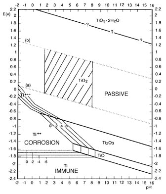
A study of the corrosion resistance of titanium is basically a study of the properties of the oxide film. The oxide film on titanium is very stable and is only attacked by a few substances, most notably, hydrofluoric acid. Titanium is capable of healing this film almost instantly in any environment where a trace of moisture or oxygen is present because of its strong affinity for oxygen. Anhydrous conditions in the absence of a source of oxygen should be avoided since the protective film may not be regenerated if damaged.
__________________________________________
Dann2


So before baking , the layer is *really thin* although
it is most definitely really tough material .

It is something like a very tough "stubborn stain " in so far as a "coating" goes .

And "staining" it with something else , staining the stain
as it were is what doping accomplishes .

Part of how this happens is because the very thin coating
has columnar wells in it , pores which extend almost down to the surface of the Ti metal substrate . You have seen color anodized aluminum , well that is done by dye getting trapped in the pores .

Now suppose instead of dye , we used something that can conduct electricity and it reaches down deep into
the pores where there may be only one molecule thickness
of TiO2 , or that a reaction occurs there which changes
that thinnest molecular layer of TiO2 into something modified to conduct electricity better . Current flows right up through those "dopant filled channels" that are like stalagtites suspended from the conductive layer above , reaching downward to the Ti metal floor , ( theoretically speaking :P) It takes an electron microscope to see this stuff , and unfortunately , I don't have one . So no picture requests , please :D

IIRC , it takes about 360 C to develop the cobalt nitrate .

With regards to the spinels and substituted spinels ,
too much heat leads to different materials , so they definitely can be overbaked as well as underbaked .

The bimetal spinels are tougher coatings than the
plain cobalt spinel . Zinc was the best of these IIRC .

Copper is another one that had good electrical properties ,
as an added bimetal with cobalt , and I'm reviewing
to see what was the deficiency there if any , for chemical resistance perhaps or some other factor that made it
not get much attention , as did the zinc bimetal with cobalt . I think there was just some summary statement
which said that of the several tested zinc was the preferred one , but others worked also , and they didn't give complete details on all the ones that were tested ,
except for the one voltage reported for the copper and cobalt bimetal spinel .

In an electrolytic capacitor patent describing similar baked on coatings using a nitrate , it was a baked MnO2 coating ,
improved results were gotten by mixtures of the carbonate
at about 10% of the amount of the nitrate , using the carbonate as a thixotropic thickener . This same technique is possibly equally applicable to other nitrate
precursors . Also the hydrated nitrate salts can be melted for application or suspended in water or other solvents , like acetone or alcohol , DMSO . These things along with possible use of the carbonate provide some room for experimentation .

That "blue stuff" is probably the "good stuff" you are wanting .

Here's a thought , when you are sanding your spinning rod
of titanium in the drill press , try wet sanding it with glycerin
or ethylene glycol and then put it into an alcohol or acetone solution of the cobalt nitrate , see if any cobalt plates onto
it as the solvent cuts through the glycerin film . You might try
mineral oil as a wet sanding also as the Titanium may form
an alcoholate with the glycerin or glycol .

Anyway , the TiH2 schemes are for minimizing or eliminating
the development of any usual passivation layer , nipping that problem in the bud before it goes anywhere .

[Edited on 2-12-2007 by Rosco Bodine]

Xenoid - 2-12-2007 at 05:00

Rosco, do you ever get that sense of "deja vu" in this thread. :D:D:D:D

Regards, Xenoid

jpsmith123 - 2-12-2007 at 05:42

Quote:

How might one make Co Nitrate from Co Sulphate?


According to one of the handbooks I have, with regard to ethanol, CoSO4 is slightly soluble, Co(NO3)2 is very soluble, NaNO3 and KNO3 are slightly soluble, and their sulfates are insoluble; so maybe reflux the CoSO4 with KNO3 or NaNO3 in alcohol?

dann2 - 2-12-2007 at 05:43

Hello,


I have never read a patent yet where the end product (anode) was the vastly superior, long lasting, novel, better than enything before, etc etc.

Ti metal when placed in HCl (cold) and then the whole lot heated to hot, will not etch. I presume the oxide coat gets thicker and thicker as the challenge increases. If you put the Ti into hot HCl it will etch ok. Or OK in cold HCl if sasndpapered

I placed a piece of freshly etched Ti into my 500C oven for about 10 minutes. I t turned an exquisite velvet like purple.
Very pretty to look at.

My Ti strip has plated with Cobalt Oxide OK. It is like No. 50 sandpaper. When viewed under microscope it is a mass of nodules and holes. Plated for 7.5 hours. Will try in perc hlorate cell.
Connot rub off coating. It is rather weird that freshly etched Ti passived but the etched stuff that sat around for some days plated OK.

Dann2

dann2 - 2-12-2007 at 05:56

Hello,

From a thermodynamic (spelling :D) point of view LD will oxidize Ti, therefor we need an undercoat ( Pt, DTO).
Is Cobalt Oxide capable of oxidizing Ti?

dANN2

Xenoid - 2-12-2007 at 09:28

Quote:
Originally posted by dann2

I have never read a patent yet where the end product (anode) was the vastly superior, long lasting, novel, better than enything before, etc etc.


Surely you mean..... "I have never read a patent yet where the end product (anode) was NOT vastly superior, long lasting, novel, better than enything before, etc etc.":D:D

I have concentrated my crude Co(NO3)2 solution, during this process some very fine colourless crystals kept forming. I repeatedly poured of the supernatent liquid and continued concentrating to about 1/4 to 1/3 volume. The liquid is now a very dark bergundy colour, like a fine Australian red wine.;) and largish red crystals have deposited on the bottom. I have left it overnight in the fridge. I believe the earlier fine crystals were residual CaSO4 as it does have appreciable solubility.

Edit: Hmmmm.. on closer inspection the largish red crystals are actually agglomerations of finer crystals. But they are Co(NO3)2

Regards, Xenoid

[Edited on 2-12-2007 by Xenoid]

Rosco Bodine - 2-12-2007 at 11:32

Quote:
Originally posted by dann2
Hello,

From a thermodynamic (spelling :D) point of view LD will oxidize Ti, therefor we need an undercoat ( Pt, DTO).
Is Cobalt Oxide capable of oxidizing Ti?

dANN2


Sure Co oxide is capable of oxidizing it , but that is what would form the bimetal spinel or other molecular compound
interface ( substituted perovskite ? CoTiO3 ? ) .

You are going to have some sort of boundary layer that
is an intermetallic compound , or a bimetal or trimetal spinel ,
regardless of what goes on top . And PbO2 can be plated directly onto a Ti substrate in a highly acidic electrolyte .
Anyway that boundary layer is a modified solid solution sort of mixed oxides interface , or a molecular compound , and it
doesn't continue to react once it has formed AFAIK , it is stable unless it is subjected to some sort of attack by a third party temperature or chemical influence which would disrupt that stable condition . That is probably why whatever conductive interface is formed on the substrate , it is then blanketed beneath a thicker working layer to protect that interface from permeation of materials which might attack it ,
but generally that would be something from the electrolyte itself , not the coating .

@ Xenoid ,

Yeah like Yogi Berra said , It's deja vu all over again :P

Regarding patents , yeah you never see the patent declaring
that after a lengthy and costly laboratory analysis which
bears out the worthlessness of the proposed invention ,
management has decided it is only reasonable to spend
yet more of the stockholders money to secure legal protection for the intellectual property work product that
is Soooo not worth a damn and Sooo going nowhere :D

BTW , acetone will probably purify the nitrate fine as IIRC
a 50% solution is possible for the cobalt nitrate hexahydrate
in acetone .

[Edited on 2-12-2007 by Rosco Bodine]

Xenoid - 2-12-2007 at 11:53

Quote:
Originally posted by Xenoid
......but much of the rod turned a purplish colour. Initially I thought this was just dried nitrate but now I think it may have been a thin oxide (spinel) layer (similar to lens coatings). It wasn't changing much with time.....


Hmmm.. I have changed my mind on this after heating some of my purified Co(NO3)2 on a piece of metal, it dehydrates and turns an intense purplish colour just before decomposing to brownish crud. Not sure why the nitrate coating lasted in the perchlorate cell, given how soluble it is especially.

I'm harvesting a bit more Co(NO3)2 from my solution, then I'm going to recrystallise it to ensure I'm starting with a pure product. I checked with a chemical supplier here in NZ, Co(NO3)2 (lab grade) was NZ$104 for 100g + $32 postage :o:o:o so this is well worth while!

Regards, Xenoid

Xenoid - 2-12-2007 at 12:51

Quote:
Originally posted by Xenoid
Edit: Hmmmm.. on closer inspection the largish red crystals are actually agglomerations of finer crystals. But they are Co(NO3)2


Errrr... No they aren't, they are still fine, fibrous CaSO4, when harvested, and the "juice" is squeezed out they are colourless. I have concentrated the solution even more, it is very viscous and a dark concentrated red wine colour. I've put it in the fridge and several "chunky" looking crystals are now forming. This stuff (Co(NO3)2) sure is soluble, (98g/100g water). The viscous liquid should be good for painting purposes though!

Edit: ... Damn! This is more dificult than I though, the whole volume of liquid has transformed into crystals. I guess all the water has been consumed in forming the hexahydrate. I've redissolved it all and added a little more water, I'll see how it goes!

Regards, Xenoid

[Edited on 2-12-2007 by Xenoid]

Rosco Bodine - 2-12-2007 at 13:48

Xenoid , go back to next to last post on page 19 where Twospoons and I were talking about purification of the nitrate . There is a lower *Tri*hydrate that comes out
first at a higher temperature , above 56 C and that may
facilitate separation . If you decant on cooling at say 60C and harvest those crystals having formed , it should be mostly the trihydrate .

This could be a "beaker buster" so evaporation in an open bowl on a water bath might be a good idea .

http://www.sciencemadness.org/talk/viewthread.php?tid=2465&a...

More deja vu :D Something I suggested way back sort of
goes along with the "wetsanding" of the spinning rod scenario . I had thought of mixing some valve grinding compound carborundum grit with cobalt nitrate or chloride
made into a paste with alcohol or DMSO or glycerin ect.
and using the mixture as an abrasive on titanium , figuring
that wherever the oxide was abraded , the surface reaction
with the cobalt would occur , possibly resulting in an intermetallic interface . Coating and baking would then further develop it into the spinel . This method could also be applied to hydrided Ti .


[Edited on 2-12-2007 by Rosco Bodine]

Xenoid - 2-12-2007 at 16:03

Guys!....Guys!........

It's early days, but this is looking really, really promising!

Unable to constrain myself with the excitement I brushed onto an etched Ti rod, a SINGLE coat of the supernatant, saturated Co(NO3)2 solution from my crystallising pan. I shook of excess, and put it in my improvised, hot air gun oven. It was baked at about 350 oC for 10 mins. After cooling, (which takes some time for a 9.5mm Ti rod) the surface had a dark-grey to black, velvety coating. It was a bit uneven in parts and smudged slightly when rubbed with a finger. I put it in saturated NaCl solution (chlorate cell) and adjusted the current to about 50mA/cm^2 which was about 1 Amp. The voltage was 3.6 volts, a small amount of black detritus is floating around, but the anode still appears to be in good condition. After 2 hours the voltage has risen to 3.9 volts but now seems stable. Most importantly, I haven't seen any coating flaking off, it appears to be well bonded. I think the small amount of black crud floating on the surface has come from the coating surface, where it was a bit thick.

I'm very impressed with this, given that it was a quick and dirty trial before attempting the real thing. It looks and behaves like a genuine MMO anode.

I note the Patent does not actually mention the concentration of the solution to use, that's why I was trying out the saturated solution. In retrospect it appears too strong and could probably be diluted by half to produce a more even coat, not to mention the additional 11 coats!

I will report back!

Regards, Xenoid

[Edited on 2-12-2007 by Xenoid]

MMO

chloric1 - 2-12-2007 at 16:25

The true test will be week run in a 1 litre chlorate cell. If it holds up then there you go. Also, if this cobalt oxide is adherent, you can plate in the cobat nitrate/sulfate bath to buid a more robust coating. Your next mission will be to plate this with lead dioxide or manganese dioxide.

Rosco Bodine - 2-12-2007 at 16:32

Quote:
Originally posted by Xenoid
I'm very impressed with this, given that it was a quick and dirty trial before attempting the real thing. It looks and behaves like a genuine MMO anode.


Outstanding ! :D:cool::D:cool::D One coat only !

Hell , even I was figuring a minimum of three coats
would probably be needed . This is damn good news ,
I was beginning to feel snakebit on this whole deal :P

And with a bit of finesse with tuning whatever works ,
subsequent "wear coatings" to build thickness if needed ,
this thing ought to fly .

The bimetal spinels , with zinc , copper , and the cobalt ,
and the manganese - vanadium , or manganese - lead
combinations , along with a whole slew of other combinations could be workable also . DTO could go on top as a vitreous sealing layer over the spinel , if the temperature isn't exceeded which trashes the spinel .
That could be a workaround for the whole bugaboo that
involves getting a good conductive interface with the DTO ,
letting the spinel take that task . You could even come back on top of the DTO with more spinel as a catalytic baked on coating built up to a good wearing thickness , and maybe never have to electrodeposit anything as a coating .

[Edited on 2-12-2007 by Rosco Bodine]

jpsmith123 - 2-12-2007 at 17:06

Xenoid my first sample ran for a little while, then, shortly after I noticed some black stuff floating around, I took it out of the brine and wiped it, and that's when it all came off.

BTW I was wondering about trying to improvise a furnace somehow using a heat gun. How did you rig up your improvised furnace?

Xenoid - 2-12-2007 at 18:03

Quote:
Originally posted by jpsmith123
Xenoid my first sample ran for a little while, then, shortly after I noticed some black stuff floating around, I took it out of the brine and wiped it, and that's when it all came off.

BTW I was wondering about trying to improvise a furnace somehow using a heat gun. How did you rig up your improvised furnace?


Killjoy...:D

No, I've got a good feeling about this, given what a crappy effort I put into the coat. It's been going for 4 hours now, most of the black stuff appeared in the first 1/2 hour.

I've got a Black & Decker hot air gun that can sit upright on a built in stand. I fit an ~5cm x 300mm Al tube on top in a vertical orientation, so the air is blowing upwards. About 1/3 the way up the tube I drilled a small hole for a thermocouple so I could measure temperature. On the top of the tube I've got a bit of Al with lots of holes in it to act as a baffle to slow the air flow down a bit. The bottom of the Ti rod sits on the slots of the air gun and the Al tube is fitted over, so the rod is sitting at an upright angle. Make sure the end of the thermocouple is in free air and not touching the Al tube or you will get a false reading.

I was going to say I saw an old toaster mini oven at a recycling centre the other day. I think I'll pick it up and fix/modify it. The hot air gun method is very cumbersome and the temperature control is not very good. In particular there is a big temperature gradient, probably 50 oC or more, between the bottom of the rod and the top, thats partly why I'm surprised this coating is holding up so well!

I'm starting to wish I hadn't wasted all that time trying to bake MnO2 coats onto gouging rods several months back.

Regards, Xenoid

[Edited on 2-12-2007 by Xenoid]

Twospoons - 2-12-2007 at 18:23

You'll find temperature control in a toaster oven to be a lot worse. The thermostats in those things are ghastly. You'd do better to work on your hot-air gun - e.g. use a steel tube, wrap it in fibreglass wool, add thermocouples top and bottom, add a flow control baffle to the inlet of the hot-air gun as a temperature control (caution required!) - or use a variac to control the heater (better). You should be able to get a nice steady flow of constant temperature air, vs 40C of thermal cycling in an oven.

dann2 - 2-12-2007 at 18:50

Hello,

About ovens, mine consists of a nichrome wire hung in a box made from domestic tyles surrounded by perlite and the whole lot wrapped in fiber glass (roof insulation). The heater is 'controlled' with a variac, in other words it is not controlled. The oven holds the correct temp. when the variac is set a a certain voltage. A clamp meter on the ac input lets you keep an eye on curretn going into heater if you so wish. It takes the oven about 4 hours to warm up and stablaize.
The toster should work OK if you have a variac and take out the toster controller yoke. Remove anything that is liable to go on fire (wire with plastic insulation) and wrap the lot in fiber glass. If you only need to go to 350C fiber glass shoud stick that. You need to go to clost to 500 if doing DTO.
The heat gun is more universal though!


Not having much luck with the Co plating stuff:

I tried out my Cobalt Oxide on bare Ti anode. It passivated within about one minute.
Current density was 100mA per square cm.
700g per liter Sodium Chlorate (Perchlorate cell).
Large quantity of bubbles came off of anode while it drew current.
The Cobalt oxide was completely stripped off the Ti at the surface of the liquid. There is a gold colour on
the Ti where the stripping took place, (Co metal ?). It is quite possible that the gold colour is there all
the time and when Oxide was stripped away cleanly the gold showed. I thing I can see gold color when
I scrape off Oxide with needle.
There is black suspended solid in jar due to this
Oxide stripping.

Coated a DTO on Ti strip with Cobalt Oxide. Similar set up as to last try on bare Ti.
It coatd OK. I only coated for 3 hours as the pH was getting very low (1.7) and I was afraid
the coating would start to strip off (or some such) so I stopped it. Looks similar to last attempt under microscope, just thinner.
Put it into Perchlorate cell. It is going OK. Large quantity of bubbles coming off anode. Black scum appearing on liquid surface.
It has been going for about one hour, no sign of any Perchlorate .............yet???????

Put DTO on Ti strip into Perchlorate cell to see how DTO would hold up in a Perc. cell.
It has already done 56 hours in a NaCl solution.

Dann2

jpsmith123 - 2-12-2007 at 19:03

How hot can a toaster oven get? I didn't think they would go much over 250 degrees C, which is probably not enough.

Anyway, my latest experimental anode is in the plating tank right now, and it has behaved differently from its predecessors. This one seems much better, electrically, so far. Unfortunately, somewhere along the line I mixed up my array of Ti samples and I'm sorry to say I don't know how this particular piece was prepared. It'll be my luck that this one will work very nicely and I won't be able to duplicate it.

Toaster Oven

Xenoid - 2-12-2007 at 19:14

I said fix/MODIFY ....:D

I'm thinking about adding extra elements, fitting a thermocouple feedback triac energy controller and maybe a small metal fan on a metal shaft driven from outside!

Cobalt spinel coated rod still stable after 5 hours...:D

I'm wondering if a new thread should be started for cobalt oxide coated anodes, as Rosco points out there is a lot of scope for experimentation here. It's getting a bit removed from LDO anodes and this thread is getting too long!

Regards, Xenoid

chemkid - 2-12-2007 at 19:16

with some effort i am sure i could get my toaster oven up to 300 C, but at that point a small foudry or furnace might be nice instead.

Chemkid

jpsmith123 - 2-12-2007 at 19:43

Making it go from 250 to 500 C sounds more like "redesign" than "modification" :P.

Anyway, what I'd like to do is find a large sized rectangular "microwave kiln", but the only ones I've ever seen are rather small cylindrical ones.

Rosco Bodine - 2-12-2007 at 19:43

Lead melts at 327C . I wonder if you couldn't just lay
your coated Ti in a trough of melted lead where it would float like a cork and bake in the bath . If the lead didn't
react with the oxide , this might be an easy way of getting a good even heating .

dann2 - 3-12-2007 at 10:33

Hello,

or would a alloy of Sn and Sb melted at 500C cause an oxide coat (a doped one) to form on freshly etched Ti that was dunked into it.

A pipe dream perhaps.

Dann2

12AX7 - 3-12-2007 at 11:23

I doubt it. Possibly you might have some luck if you got a fluoride-based titanium flux and tinned the base metal with that alloy, then annealed in air.

Tim

A few helpful references to follow

Rosco Bodine - 21-12-2007 at 03:37

Effect of addition of lead acetate during the deposition of lead dioxide from the nitrate bath

Attachment: Effect of addition of lead acetate during the deposition of lead dioxide from the nitrate bath.pdf (657kB)
This file has been downloaded 1353 times


Rosco Bodine - 21-12-2007 at 03:38

The fabrication of lead dioxide layers on a titanium substrate

Attachment: The fabrication of lead dioxide layers on a titanium substrate.pdf (1.7MB)
This file has been downloaded 2569 times


Rosco Bodine - 21-12-2007 at 03:39

Oxygen overpotential of graphite-substrate lead dioxide anode

Attachment: Oxygen overpotential of graphite-substrate lead dioxide anode.pdf (183kB)
This file has been downloaded 1502 times


Rosco Bodine - 21-12-2007 at 03:41

Lead dioxide coating obtained by pulsed current technique

Attachment: Lead dioxide coating obtained by pulsed current technique.pdf (501kB)
This file has been downloaded 1189 times


chloric1 - 21-12-2007 at 15:54

Quote:
Originally posted by Rosco Bodine
Effect of addition of lead acetate during the deposition of lead dioxide from the nitrate bath


Thank you ofr all these wonderfull references Rosco!! I sincerely appreciate it. I especially took notice about the acetate addition to lead dioxide plating bath as a pH buffer. This seems analgous to jpsmiths post about plating cobalt metal from cobalt sulfate and cobalt acetate. He stated that the sulfate yeilded crappy deposits while the acetate yielded smooth shiny ones. After reading this I was thumbing through cobalt chemistry in my Merk index and noticed they said a dilute solution of cobalt acetate had a pH of 6. I thought to myself this is pretty high for a semicovalent metallic salt. My understanding is that most nickel and cobalt salts of strong acids had pH's of like 4 or 5 in dilute solution. With this thinking I came to this conclusion that wild pH flunctuations caused stressed out crap electrodeposits.

Not only do I want to try a lead acetate addition to the nitrate bath but I would also like to use cobalt acetate on titanium hydride to plate cobalt metal prior to baking spinels.

Rosco Bodine - 21-12-2007 at 20:40

Yeah that article supports an idea that I had expressed earlier in the thread when observing an overlap in the
optimal pH ranges for the conditions for plating alpha PbO2 from an acetate bath and the conditions for plating the beta PbO2 from a nitrate bath . I supposed
( informally hypothesized ) that by varying the voltage using a mixed acetate - nitrate electrolyte , a mixture of alpha and beta PbO2 might result , giving a stress free deposit in thick layers .

IIRC , I didn't really think then about the possibly useful fringe benefit of the acetate acting as a buffer , as of course it is recognized now that it may solve that headache of pH regulation needed for quality platings , simply to use a mixed acetate - nitrate plating bath for that reason alone , avoiding the misery of pump circulation
of the electrolyte through neutralizers .

This would probably work pretty well also for the
MnO2 plating scheme which uses MnCl2 to advantage
over the sulfate , using an acetate as a buffer .

The limiting factor with this method is that it is a
spin coating . All of the stationary samples showed pinholes . So that's a complication which may rule out
this particular method from consideration . It may be that a surfactant or nickel nitrate or NaF additive could improve the results for the stationary plating , along with the current pulse deposition scheme .

I think probably the bismuth containing PbO2 or one of the other patent processes would probably give satisfactory results . But this mixed acetate - nitrate scheme could be an area for experimentation .

[Edited on 22-12-2007 by Rosco Bodine]

chloric1 - 22-12-2007 at 07:02

Quote:
Originally posted by Rosco Bodine
The limiting factor with this method is that it is a
spin coating . All of the stationary samples showed pinholes . So that's a complication which may rule out
this particular method from consideration . [Edited on 22-12-2007 by Rosco Bodine]


Rosco, I don't understand this. The article gives specific rpm speeds and only an appropriate drill in a drill press setup with sliding anode contact possibly made of brass.

Rosco Bodine - 22-12-2007 at 07:34

Quote:
Originally posted by chloric1
Quote:
Originally posted by Rosco Bodine
The limiting factor with this method is that it is a
spin coating . All of the stationary samples showed pinholes . So that's a complication which may rule out
this particular method from consideration . [Edited on 22-12-2007 by Rosco Bodine]


Rosco, I don't understand this. The article gives specific rpm speeds and only an appropriate drill in a drill press setup with sliding anode contact possibly made of brass.


You are right it's not a problem if you are using a cylindrical
form anode :D Maybe a vibrator of some sort would do
better for a plate form anode . Really that's what I was
thinking about using anyway . I think vibration , might
keep the bubbles shaken loose for the stationary anode .

This is one of the uncertainties which would have to be addressed by experiment if a plate substrate is used .

Actually I favor a solid rod form anode since it is the most
convenient for many reasons .

[Edited on 22-12-2007 by Rosco Bodine]

chloric1 - 22-12-2007 at 18:40

Well, I have read more often than not that rods are usually the recommended shapes and I have seen where plates need to have there edges rounded. I just won about 20 1/4" Ti6Al4V rods on ebay for $45!:cool: I will now be able to expand and play with more baked on interface ideas. Also, I will be able to easily make a profit reselling most of what I bought back on ebay. :D

Rosco Bodine - 22-12-2007 at 19:46

The 1/2" CP grade is probably best all round candidate but the other alloys may work okay too .

A common diameter for patent test examples is 1/2" and that up to maybe 3/4" is good for a solid substrate anode . IIRC the larger you go thereafter
runs the risk of differences in the thermal expansions causing stress fractures in the coatings for solid cores ,
and a hollow tube , or perhaps a perforated sheet is
then needed .

dann2 - 24-12-2007 at 10:10

Hello Folks,

I enclose some correspondence I have had with RongPeng regarding [DTO (alone) and DTO with LD on top]
anode making. He had made many DTO (alone) + LD anodes(LD on top of DTO, Ti substrate).
He has not made any Chlorate or Perchlorate with andoes as he uses an accelerated electrochemical test
for to test them, Electrolyzing H2SO4 .
I wonder how relevent to (Per)Chlorate making the accelerated test is?
Our Chlorate cells have high pH. The pH of Perchlorate cells seems to be all over the place
+ the added complication of the different species thrown in for good measure!

Dann2

Attachment: rp for SciMad.txt (18kB)
This file has been downloaded 1043 times


tentacles - 27-12-2007 at 11:47

Has anyone tried plating PbO2 on a valve metal other than Ti? Specifically Nb and Ta, as mentioned in several patents, are supposed to make good adhering, long lasting anode cores. I have been wondering if anyone has tried? I know Ta and Nb can be pricey, but so can things like SnCl4 et al.

Xenoid - 27-12-2007 at 12:32

@ tentacles

If people are having problems with Ti, I don't think trying to use even more expensive and exotic metals is going to help. The same problems will apply, perhaps even more so.

I would like to see someone with PbO2 plating facilities and chemicals, try plating over a Co3O4 baked on interface layer. The Co3O4 layers are extremely easy to put on Ti and it costs virtually nothing to do. Two layers would be enough!

If someone doesn't do this soon, I will try it myself .... :o

dann2 - 27-12-2007 at 15:32

Hello,

Quote:
Originally posted by tentacles
Has anyone tried plating PbO2 on a valve metal other than Ti? Specifically Nb and Ta, as mentioned in several patents, are supposed to make good adhering, long lasting anode cores. I have been wondering if anyone has tried? I know Ta and Nb can be pricey, but so can things like SnCl4 et al.


Same problems apply. Seen a Ta substrate anode but it was a massive anode. Substrate was ignored when it went into service.
I tried putting DTO on Tungsten but did not succeed. I used SnCl4:5H20 + other bits (had success using Ti with same solution).

About to wheel out the lead plating tank..........

Dann2

tentacles - 3-1-2008 at 16:53

I've been plating another anode, this time using (almost) hashashan's method. Here's a chop of my post from (APC)
"I kicked my ass into gear today and am trying another plating session. I sanded the Ti strip with P220 sandpaper, and then used my dremel to round the edges nicely, wet sanded (EtOH) with 1000 grit SiC paper, and then painted the side that I hope to not plate with some cheap black spray paint. I covered the edges with hot melt glue, making sure to heat the Ti up so it would stick, and also covered the painted side with more hot melt glue. I then sanded the working side again with 1000 grit paper, then tacked on the scotch brite.

I prepared 2L of solution as my bath:

250g/l of Pb(NO3)2
1.65g/l of NaF
15g/l of Cu(NO3)2
2.2g/l of 50/50 200/325 mesh SiO2
10ml/l of 80% HNO3

I'm running it at 52C on my hotplate, with the stir bar running.
Current density is 15ma/cm2, running off 3.3v on my new (and cheap) ATX PSU. PbO2 started plating immediately when I turned on the power.

edit: Came home last night and it was pulling 845ma, which was a bit high for my liking - I know it's in the acceptable plating current range, but I bumped the voltage down to 1.7V (5.0v - 3.3v). It's pulling ~5ma/cm2. Plating continues."
Today:
"Anyways I decided to stop plating this anode, weird things were starting to happen.. I peeled it off the Ti, which wasn't so much peeling as breaking off a few little bits to release it.. It actually curved while plating, which is very strange. After I got it off, it was somewhat broken, so I lassoed it with some wire and dunked it in to plate it back together.. The result.. 168.7g of very ugly PbO2. I doped the plating solution with NaF, the resulting PbO2 is smooth, and shimmers."

http://www.apcforum.net/files/DSCN6808.JPG
http://www.apcforum.net/files/DSCN6803.JPG
http://www.apcforum.net/files/DSCN6800.JPG
http://www.apcforum.net/files/DSCN6798.JPG

hashashan - 4-1-2008 at 07:11

Way to go .. looks just like my own but a bit smaller.
Seems like my method is good :)
however the Pb nitrate seems quite low 250 g/l ... i used more then 500

[Edited on 4-1-2008 by hashashan]

tentacles - 4-1-2008 at 11:38

I need to make more, but I'm out of calcium nitrate.

hashashan: Did your anodes end up curling like mine did? Interestingly, the curved sections didn't crack, I wonder if they are from the compression stress, or if they are from the NaF doping. I can't wait to get home and silver/copper plate this thing, and pump chunky amps into it.

[Edited on 4-1-2008 by tentacles]

hashashan - 5-1-2008 at 05:52

My Ti plate was very strong so there was no bending ... but the bending issue is known

chloric1 - 5-1-2008 at 06:31

So you guy are using titanium as a substrate to form the massive lead dioxide? I think the bending is from stresses from not ashering to the passivated titanium and the dropping pH of you plating bath. Try baking a cobalt spinel anoded and plating that with PbO2. Also, you are plating at WAY too high current density.

tentacles - 5-1-2008 at 06:43

chloric: the current for the *whole anode* was 845ma - it actually topped at about 1100ma at one point, but that's for a 14x2cm area. 39ma/cm2 is maybe a bit high for my liking but most patents suggest going as high as 50ma/cm2.

hashashan: The Ti plate didn't bend, it was only the lead dioxide. The plate is actually 1mm thick 6-2-2-2 Ti, so it's pretty stiff. I looked at the bits I broke off to remove it from the Ti, and there are probably pinholes - I'll take a super closeup with the camera later. The plating is very smooth, the nodule shapes that always seem to form are largeish, and the shimmering effect is quite striking.

dann2 - 6-1-2008 at 14:31

Hello Folks,


Quote:
Originally posted by tentacles
I need to make more, but I'm out of calcium nitrate.

hashashan: Did your anodes end up curling like mine did? Interestingly, the curved sections didn't crack, I wonder if they are from the compression stress, or if they are from the NaF doping. I can't wait to get home and silver/copper plate this thing, and pump chunky amps into it.

[Edited on 4-1-2008 by tentacles]


The shimmering effect is a sight to behold. It looks like very fine blue/black velvet.
If you are going to plate more from the same tank you need Lead Carbonate or Oxide or some such to neutralize the formed Nitric acid and add more Lead Ion. Perphaps you are making Carbonate or Oxide with the Ca Nitrate.
Then again fresh new tanks ALWAYS seem to give better coats. Products build up in the plating tank that seem to interfere with plating. Nitrites being one.

I have seen massive anodes from the patents or somewhere which used an Iron substrate pipe. The funny thing is that they plated the Lead Dioxide on the inside curve. Perhaps this 'inner curve plating' helped reduce or counteract the stress in the Lead Dioxide.
Perhaps if one were to bend the Ti before plating and plate on the inside curve it might help to give more reliable anodes.
Call it the 'Hashashan method modified by curve' (or some such) :D

Dann2

chloric1 - 6-1-2008 at 15:29

Better yet, just get on ebay becuase buying titanium anywhere else I think is a rippoff. I regularly see titanium tubing. It just a matter of getting the right diameter. Cut a slit lengthwise and open slightly then apply a resist on the outside. You are ready to plate.

dann2 - 6-1-2008 at 19:04

Hello,

When plating on inside curve you may get less nodules etc at the edges too. (Guessing).
Dann2

Twospoons - 6-1-2008 at 20:49

Funny, I've often thought plating the inside of a pipe would be better. So many refs to stressed deposits cracking implies (to me) material under tension - ie outer layers too "small". It seems to me that plating inside a curve would reduce this tension, maybe even put the PbO2 under compression - which would be fantastic for mechanical strength. Just like pre-stressed concrete!

dann2 - 7-1-2008 at 17:26

Hello,

There is a bit of reading regarding bending and stress in US Pat. 4064035 below.

I cannot find the article/patent that described growing massive anode on the inside of an Iron (O no :D) pipe. Anyone know where/what it is?

Beta LD is what we want on the outside of anodes. Alpha has better adherence to stuff. This is irrevelent with the Scotch cloth anodes. Alpha is usually deposited from Alkali baths (Tartarate, Plumbite) Beta from Lead Nitrate bath.
RongPeng has said that Alpha LD comes from a Nitrate bath when current density is high (70mA per cm squared) and Beta when current denisty is lower (40mA and less).
Perhpas you could deposit alternative Alpha:Beta etc by varing current density. Just a guess. The Apha made this way may not have similar stress (or lack of stress) as per the Alpha coming from an Alkali bath. (as in the patent.)
Two baths = lot of 'hassle'.

@TwoSpoons
This is a good idea. The original 'inside job' (using an Iron pipe) was for massive anodes. The pipe was cut upon and LD removed. They were called "pot core" anodes (as far as I can remember) for some reason or other.
If you were to leave the LD in place in the pipe that would surely be a sturdy set up. The pipe in this case would have to be a DTO'ed (or some such) pipe, or perhaps a half pipe. (semi circle).
Now a Ti rod/pipe down the middle for cathode.................


Nitrites in tank: See US 2994649 where they add Hydrogen Peroxide to eliminate.
Dann2

[Edited on 8-1-2008 by dann2]

[Edited on 8-1-2008 by dann2]

Attachment: US 4064035 Alpha + Beta + Massive.mht (57kB)
This file has been downloaded 1087 times


hashashan - 8-1-2008 at 00:00

Guys really I think that a hard substrate will eliminate the bending, it worked for me.

12AX7 - 8-1-2008 at 08:02

When I tried plating PbO2 onto graphite (in an acetate solution), I got spots of curly, flaking PbO2.

Tim

tentacles - 8-1-2008 at 23:56

hashashan; The ti strip I used is 1mm thick - it did not bend, the PbO2 plating curled during the process. I'll never know how this one would do as I broke it while trying to attach the electrical conection. The NaF doped PbO2 does not seem to take silver plating well.

hashashan - 9-1-2008 at 00:54

very weired. You did evry thing I did and you got bending.

hashashan - 11-1-2008 at 01:37

Finally I managed to rewire my PSU (after so many were scorched and sent to the trash) now I can set it to any voltage in this range 2-6 or 8.5-13 the 6-8.5 Is missing (just couldn't remove the overvoltage protection) and that would be the most convenient voltage ... well anyway back to our business, launched my anode into a chlorate cell first hopefully to continue to perchlorate on the fly. Now it is pumping 5.5 amps at 6 volts, tried it at 8.5 and the current is 12 amps(to risky for my shitty PSU.. well have to wait for one week to see results...

dann2 - 14-1-2008 at 14:59

Hello,

Regarding PSU from computers. It would be better to obtain/attach a constant current circuit to what ever voltage output would be fairly close to the max. output voltage you may need. This would suit plating/electrochemical cells.
Perhaps some of you guys (hint hint) would design a max. simplicity circuit that simply attaches to some voltage combination of the PC PSU and shove out a programmed current. Tim did a good circuit (I did not build) but the constant current modules are specific to that circuit. If a more 'stand alone' constant current circuit could be had it would be very useful.

Anyhows. I attempted to coat my DTO anode (this DTO anode has been sitting on my bench for the last 1.5 months) with Alpha LD, from a Lead Plumbate bath.
Litharge was dissolved in 2N NaOH solution.
I cannot get this (damm) bath to plate anything. It will not plate DTO. Tried freshly etched Ti and it passivated immediately. A brown loose coating of LD went onto the DTO but it does not increase in thickness and rubbs off.
I tried a piece of Graphite that had been previously coated with Beta Lead Dioxide (from Lead Nitrate bath) but no Alpha coating formed.
I tried changing the NaOH to a different hardware store variety (99-100%) but it made no difference. The litharge is Technical grade. The water is clean rain water.
Lots of Lead appears on cathode.
There is lots of gassing on the anode and cathode.
Would this type of bath be very sensitive to contaminents?
Don't have a clue why it will not work.
It is mentioned in lots of patents.
I am going to try a Lead Tartarate bath next.

Dann2

[Edited on 14-1-2008 by dann2]

[Edited on 14-1-2008 by dann2]

12AX7 - 14-1-2008 at 17:18

Isn't plumbate more soluble and acidic than plumbite? Why would PbO2 deposit in such a bath?

Tim

dann2 - 14-1-2008 at 18:12

Hello,

Quote:
Originally posted by 12AX7
Isn't plumbate more soluble and acidic than plumbite? Why would PbO2 deposit in such a bath?

Tim


I might as well be blunt/honest:
I have no idea!

From a patent: (lots of patents use this bath to deposit Alpha LD).

__________________________________________
A 4 square inch area of this titanium plate was then coated with a layer of lead dioxide by electroplating for 20 minutes at room temperature at 0.3 ampere per square inch (46.5 milliamperes per square centimeter) in a sodium plumbate plating solution containing NaOH (80 grams per liter) and PbO (30 grams per liter).
___________________________________________-

Dann2

chloric1 - 14-1-2008 at 18:36

Quote:
Originally posted by 12AX7
Isn't plumbate more soluble and acidic than plumbite? Why would PbO2 deposit in such a bath?

Tim


To be honest, I thought tartrate was REQUIRED in order to get alpha PbO2. Never heard of a working plumbite or plumbate PbO2 bath. THere is no reason why such a bath would deposit anything BUT lead metal on the cathode. The tartrate bath prevents the distribution of free Pb++ running around naked in the electrolyte doing God knows what:D:P

Alkaline Lead EDTA would be a fun experiment too. :o

dann2 - 14-1-2008 at 19:24

Hello,

I will certainly have to do something about that streaking Lead ions. :D
Heaps of patents have given the straight NaOH + PbO bath above for plating Alpha.
Some eg's
http://www.geocities.com/CapeCanaveral/Campus/5361/chlorate/...

Anyhow I cannot get it to work so will move to Tartarate.

Dann2

Rosco Bodine - 14-1-2008 at 21:10

Quote:
Originally posted by dann2
Hello,

Regarding PSU from computers. It would be better to obtain/attach a constant current circuit to what ever voltage output would be fairly close to the max. output voltage you may need. This would suit plating/electrochemical cells.
Perhaps some of you guys (hint hint) would design a max. simplicity circuit that simply attaches to some voltage combination of the PC PSU and shove out a programmed current. Tim did a good circuit (I did not build) but the constant current modules are specific to that circuit. If a more 'stand alone' constant current circuit could be had it would be very useful.

Dann2


Actually DerAlte and I were back and forth for a couple of months via U2U's in an effort to pin down what should work , and I started to post the product of that exchange as a Christmas present especially for 12AX7 , as an example of some engineering which might have some chance of working and working efficiently . With all the excitement
over the cobalt spinel interface that Xenoid stirred up with
his heat gun powered anode hot potato cannon :D .....
I almost forgot about the constant current output module which was so long being sorted out . Besides , school was out for Christmas break and I felt it would probably be better to wait until the holiday was over , resuming the learning experience and all when it's time for classes to begin again :P:D;)

Anyway it's damn well not so simple as one might hope .
I even got in touch with tech support at one of the world's leading technology vendors for this sort of thing , trying to
get some disclosure concerning the one and only one
lab testing which has been done paralleling this module ,
and they promptly "lawyered up" with the sorry it's proprietary black box technology kind of reply that told
me less than I already knew before inquiring , mainly
just to confirm that their "unpublished solution" was
probably just about identical to what DerAlte and I already
sorted out and figured out as being likely .

The constant current output module is complicated enough by itself before being plugged back into that earlier control stage which was designed before and did check out on paper as valid AFAIK . And I haven't redrawn the schematic with the finalized design for the *pair* of paralleled output modules as I have to rescale the entire drawing for it to fit and have been thoroughly occupied otherwise too much to get to that finishing of the whole schematic .

Looking at the complexity of the whole thing I figure it's good
technically... but it's not really a "basic" electronics sort of project but is a seriously high current industrial duty kind of chip controlled power supply which would take some skill and balls to build .

However , I will post it back in the other PS thread .
And I do have the circuit modeled in LT Spice if anyone
wants to look at the pulse response simulations ect .
The sims indicate it will probably work okay .

[Edited on 14-1-2008 by Rosco Bodine]

Xenoid - 14-1-2008 at 22:55

Quote:
Originally posted by dann2
Regarding PSU from computers. It would be better to obtain/attach a constant current circuit to what ever voltage output would be fairly close to the max. output voltage you may need. This would suit plating/electrochemical cells.
Perhaps some of you guys (hint hint) would design a max. simplicity circuit that simply attaches to some voltage combination of the PC PSU and shove out a programmed current. Tim did a good circuit (I did not build) but the constant current modules are specific to that circuit. If a more 'stand alone' constant current circuit could be had it would be very useful.


Dann2, whilst a constant current power supply is very useful in a plating situation, I don't really think it's called for with amateur (per)chlorate cells. For electroplating purposes just get a laboratory power supply with constant current/voltage, these are pretty cheap these days, and indispensible for experimental electrochemistry. These are good for 3 - 4 amps which is all you need unless you are plating something huge.

I am currently running my "Big Bertha" chlorate cell almost totally unregulated ( variac + transformer) it's running at about 24 amps and only goes up and down by 1 or 2 amps from day to day, I rarely touch the variac.

For cells, try using the simple circuit posted by Aqua_Fortis_100% on page 8 of the "KClO3 ......" thread;

http://www.4shared.com/file/32991572/7dcdf563/Regulador_0_a_...

I've tried this circuit and it works fine. It's just a simple current regulator attached to the +5 volts of a computer PSU. It uses a cheap power transistor to control the current and only uses a handful of parts. I've picked up another two computer PSUs for a few dollars and I'm going to mount a current control like this on each of them. Big heatsink on one side and control potentiometer on the front. It will save messing around getting just the right high wattage resistor for current control.

tentacles - 15-1-2008 at 10:12

dann2: In belated response to your post at the top of the page; I use Ca(NO3)2 and CuSO4 to make Cu(NO3)2 and then add Pb metal to displace the copper. It works quite well, though there remains a bit of copper in solution afterward - not a big problem since I'd add some anyways.

dann2 - 15-1-2008 at 12:13

Hello,

About the circuit that Aqua_Fortis_100%:
Is it a constant current output or constant voltage?

I have a lab power supply (current limited) It would be nice to have about 5 of them for all the plating testing etc.
The PC supply with constant current modude would be nice (I think).
A hugh complicated circuit is of NO USE WHAT SO EVER (just in case someone is thinking of posting one!!!)

@Tentacles Does it take long for the Pb to displace the Copper. Do you cut it up finely.

Dann2

Xenoid - 15-1-2008 at 13:14

Quote:
Originally posted by dann2
About the circuit that Aqua_Fortis_100%:
Is it a constant current output or constant voltage?


No Dann2, it's not constant current, it utilises the constant voltage computer PSU, it just behaves like a variable resistor, and will get hot if you have a lot of current flowing. The circuit is only 2 transistors, 2 resistors and a potentiometer, you can't get simpler than that! You can just connect your (per)chlorate cell and dial up the current, you may need to adjust from time to time as the cell parameters change. It saves fiddling with different value resistors to get the right current for individual cells.

Twospoons - 15-1-2008 at 13:40

You can get simpler if all you want is a bit of additional stability. Just add an ordinary lightbulb in series. As the current drops, the filament cools a bit and its resistance drops, helping to prop the current up. By no means perfect, but very, very simple and cheap. And you can see at a glance if the power has gone off!

tentacles - 15-1-2008 at 18:13

dann2: not long at all, especially if you take strips of Pb (I have a sheet of Pb roof flashing) and hang them from your beaker, and stir it with a stir bar or something. I'd say 24 hours is probably sufficient - you could certainly go longer, and I have, but after some point it's diminishing returns. I've found if you leave (excess) lead hanging/sitting in the solution for too long, the lead seems to start falling out of solution as (Pb(OH)2 ?), whilst more lead metal dissolves. I haven't really bothered to see if this continues until all the lead metal is converted, but it's certainly possible.

A second try at a massive PbO2 anode has bent the Ti strip in a slight curve - this time the Ti was pitted so the PbO2 seems to be sticking like a bitch. I haven't tried to peel it off - I thought I'd plop it in a cell for a while and see if I can't get it to plate off as the Ti passivates.

dann2 - 16-1-2008 at 16:58

Hello,

Finally got around to coating the Magnetite-on-Ti anode.
It appears that Magnetie will take a coating of LD OK.


The photo was taken when anode was wet. The indends are caused by the bubbles when plating. I put on an Alpha then a Beta layer.

Testing to commence forthwith.

Did the beads/ceramic particles word well in the cells that you guys used to make your massive anodes?

Dann2

Or should I have said I coated a valve metal previously coated with a mono metal inverse spinel with Plumbous(ish) Oxide to achieve the best ever......................

[Edited on 17-1-2008 by dann2]

Twospoons - 16-1-2008 at 17:17

Have you ever tried putting an aquarium bubbler beneath the anode while plating? That might be an effective way of removing bubbles from the anode and agitating the bath at the same time.

tentacles - 16-1-2008 at 20:12

I found the silica grit just got caught in the fibers of the scotch brite, but on the exposed PbO2 it works pretty well. I did take some fairly high res pics of the anode.. http://www.apcforum.net/files/DSCN6800.JPG

dann: I've never had bubble that big form on my anodes during plating but I usually keep the current density low - I like 15ma/cm2. Also, I ALWAYS plate on a stirring hot plate (ensuring a controlled temp) with a 6cm stir bar going as fast as I can spin it.

I will try making a Ti/Co/DTO/PbO2 anode soon. I have more Ti on the way for to better experiment. I need more cathodes!

[Edited on 16-1-2008 by tentacles]

 Pages:  1  ..  6    8    10  ..  12