Sciencemadness Discussion Board

homebrew aspirator

blazter - 28-1-2003 at 18:42

After seeing various recirculating aspirator setups i've noticed that the authors of the howtos didn't mention where they actually obtained the aspirator unit. Now, i have seen them for sale at online vendors, but im wondering if a similar unit could be constructed from readily available hardware store supplies? I'm thinking about a "T" connector and a few reducers, or simply making a "T" by drilling some copper tubing and soldering a smaller tube in it. Is this more work than its worth assuming it MIGHT work? Also, anyone have any suggestions for dimensions/reduction ratios?

Polverone - 28-1-2003 at 20:00

Given that you can get a real aspirator for something like $10, it does seem like more effort than it's worth. I have a soft spot in my heart for homemade equipment, though.

Actually, here's another question: just how would you go about attaching an aspirator to a normal home faucet, or even an outdoor spigot? My faucets don't have the nifty ridged, tapering connectors that lab ones do.

NERV - 29-1-2003 at 16:13

Here is a possible way to make a home made aspirator.

home made aspirator..jpg - 18kB

blazter - 29-1-2003 at 19:02

Thanks for the info NERV. A nice drawing but may i ask a quick question about the dimensions? Specifically, what diameter does the PVC pipe have to be that receives the water from the pen tube? I assume something like 1/2 inch would be too large.

The logistics of hooking up flexable tubing or rigid PVC pipe to a hose or threaded faucet shouldn't be too difficult. It's possible to buy threaded adapters to flexable PVC or one could go the really cheap way and cut off the end bit of a hose and use hose clamps to secure it to a piece of 1/2inch or possibly 3/4inch rigid PVC (i'm not sure off the top of my head which would fit better).

NERV - 30-1-2003 at 18:21

Well I don’t have a pen to measure the diameter of right now, but I would say the receiving should be about a 1/4 of an inch, or so wide.

perhaps this helps

Organikum - 3-2-2003 at 14:54

the pics which have been here are in the attachment of the overnext post. Some confusion, sorry.
ORG ;)

[Edited on 21-5-2003 by Organikum]

addon

Organikum - 10-2-2003 at 19:50

Some more information on the pictures.
The industrial device is a liquid driven one (water mostly). It is intended to work with a closed end, says it is connected to a tube and not just left open to air. So if this design is adapted it´s preferable to keep the end below the water surface for optimal results.

The second one is originated in a SIEMENS portable vacuum device and operates with compressed air. There is in this special case no difference to a liquid driven device, except the diameter of the nozzle which should be bigger with water.

What diameter shall the the nozzle have by principle? Depends on your water supply. It should be as wide as possible without getting a reasonable lowered pressure on the water line measured min. 50cm away from the aspirator. It makes sense to determine this before building the aspirator. Mostly you won´t need or want the max. nozzle as you won´t need these amounts of air sucked out fast. The reachable vacuum stays the nearly same.

If there is interest I can post some more information on the topic.

Here is a link to the in my eyes best webpage on chemical engineering including information on this too.
Don´t miss the distillation pages! CheResources

as the pics are gone

Organikum - 12-2-2003 at 18:01

with the ftp I had my files on, I add them here as attachment.
I packed some more construction drawings and two tables for vacuum to reach with what pump.

sorry for the inconveniance and the three posts in line.
ORG

Attachment: Aspiratores.rar (116kB)
This file has been downloaded 3636 times


Cool

blazter - 14-2-2003 at 21:54

Wow, didnt expect full blueprints! very good info indeed. If i get time I think i'll try constructing one from pvc tubing and the pen tube method. Currently I'm spending my free time on the tube furnace project (the thermocouple electronics and MoO3 is going to get ordered soon for that)

For a quick buildt but functional device

Organikum - 16-2-2003 at 03:53

You may use this for dimensioning:

xx

It´s in millimeters ;)

The aspirator ready buildt looks like this if metal tube is used:

xx

This is functional, and tested. There are optimisations possible of course but for most applications this will do fine. For higher vacuum I would suggest to stage up a fridge compressor in line with the aspirator. This setup should deliver effective vacuum in the range of <15 torr. Thats better as many of the praised "yellow jacket" pumps are able to do for costs below 50?/$ including all tubing.

As soon as I have some spare time I will do some tests on optimizing an aspirator, as I am now sure that the vapour pressure of water doesn´t limit the maximal reachable vacuum, but the velocity does. I will try to adapt some principles of Viktor Schauberger´s work on water and vortexes, where he describes ways to reduce the resistance in tubes to near zero. It´s no quack, water powered electricity plants working by these principles exist.
Has anybody a bright idea how to calibrate a vacuumeter? To build one by means of a thermocouple is easy.....

ORG

xx - pics gone. I repost them as attached file - have a look down the thread. :)

[Edited on 8-4-2003 by Organikum]

PoDuck - 17-2-2003 at 23:15

I think that the previous post is actually a good design. Basically, you need to make a venturi design, and the professional ones and the one above seem to have a chamber like design to keep the water from having a chance to leave the inlet hole so easily. Before I got to the bottom of the page, and saw this design, I was going to suggest a design that would work by having a male threaded end to work with the normal household faucet, and instead of a T, have kind of a y shape like the attached picture. This would create less turbulence at the entry point since the angle is lower where the water would hit, and would be less likely to find it's way up the tube to your chemicals.

<img src="http://poduck.dyndns.org/aspirator.gif" width="127" height="300"><br />

With this, you could make it out of copper tubing and solder. It would not be as unreactive with most corrosive gasses as PVC, but it would be more sturdy.

[Edited on 18-2-2003 by PoDuck]

aspirator.gif - 2kB

Venturi and copper

Organikum - 19-2-2003 at 01:10

Actually all aspirators use the venturi principle to function. And you may use copper or what you like to use the material is not critical - if you fear corrosion paint it.

But sorry to tell, your design won´t work as it misses the nozzle for velocity and more important the outlet has an far to wide diameter. The air would just flow up at the sides and you have no vacuum at all. The smaller diameter of the outlet is the seal. If you would like to use the whole diameter of the waterline you would have to widen the part where the air inlet is for applying the venturi and it would be not very strong for lacking velocity. The form of the air inlet isn´t critical at all - suckback is prevented by an separate one-way valve (ball-type).

I think also you have an misconception regarding the difference between an aspirator and an air-pump which are very similar but not identical:
A aspirator is for applying and holding upright of a vacuum what includes only very little airflow whereby an air-pump is optimized for processing maximal amounts of air what includes an permanent airflow. One works on a maximal pressure difference the other on maximal flow.
There is naturally no exact borderline between the two devices.

Essential for an aspirator are:
- A nozzle for the working fluid gaining velocity.
- A chamber where the venturi is applied.
- A narrowing working as seal for preventing pressure equalization.

Complaints please to Mr Venturi who made this up.

ORG

missing pictures repost

Organikum - 8-4-2003 at 00:38

the missing pics from above as attached file.

Attachment: Aspiratores.rar (17kB)
This file has been downloaded 2002 times


Eliteforum - 8-4-2003 at 02:45

I have various copper connectors (compression fittings) if anyones intrested?

Here's a list of what I have:

x1 15mm screw in end cap
x2 15mm T connectors
x1 15mm to 22mm ball valve
x1 15mm 90degree elbow joint
x1 15mm to 22mm reducer/enlarger
x1 22mm endcap with a all valve in the end.
x1 15mm endcap

All these are brand new and haven't been used.

If your intrested, let me know.

Organikum - 12-4-2003 at 08:06

thanks for the offer Eliteforum, but I doubt it being economically making sense to send the parts in the czech republic....
(in the end the customs even want me to pay duties on it)

Found this:


cute, isn´t it?

[Edited on 21-5-2003 by Organikum]

update

Organikum - 19-7-2003 at 23:48

This is a bought aspirator (the picture is negative for security reasons - and for that it may not look so unbelievable boring...)


And this is this aspirator disassembled - naked to the bone - huh!


The one mysterious part - right in the middle row of three - is a rubber thingie which shall work as suckback inhibitor - a primitive integrated one-way valve. This part in reality diminishes the vacuum and power overall significantly and suckback takes place nevertheless. Thats astonishing for a professional laboratory device.
I removed the rubbershit and a cheap ballvalve from the aquarium supply actually WORKS inhibiting suckback.

If there is interest I can measure the parts and post the dimensions.

n00dle - 5-9-2003 at 23:41

A good fridge compressor will do a 1 torr vaccum. (Boil water at room temperature.)

Problem is, it's designed to work in a hermetically sealed environment. If you use it in normal atmosphere, the compressor side will make the water in the air freeze, and then turn the insides of the compressor into mush as it trysto act as an ice cube blender.

I'd REALLY be interested if someone could suggest a way to say, remove the compressor, and regarge it, and use it to drive another device as a vaccuum pump. Like a passive system, so the fridge compressor will be happy in a 0% water environment, yet you can still passively use it for any humidity range.

Just a thought

Organikum - 26-11-2003 at 08:43

Never heard of this freezing problem before. You should tell this the manufacturers of rotary vain vacuumpumps - they will be glad to get to know why their machines are not working... LOL

Or short and cruel:
NONSENSE.

Realistic are 50torr by using a single fridge compressor, 10torr by using two staged. You may be able to get it better but thats what you can expect with a not much effort rig.

Vacuum station/ aspirator - homemade.

Tacho - 29-8-2004 at 12:48

My miserable junkyard refrigerator vacuum pump failed when I needed it most!

I decided to build a vacuum station. Went to the hardware store, and built this:


The pump is 1/4 hp and I found out that it needed a bigger water deposit, otherwise water would splash all over.

I tought that it would be easy to built an aspirator using PVC fittings so I've built something like this:


I found out it does not work! I don't know why! I have seens schematics of comercial aspirators, but they don't make sense. Why would a flow of liquid suck air around it to funnel it into the exit tube? There has to be some trick there!

Does anybody have any experience building aspirators with hardware store materials? Or know exactly how they work? Please, armchair scientists, don't give me something stupid like "it's the Bernoille principle, my dear".

My work until now looks like this (notice the Y conection of my failed aspirator):


D'OH!!

Hermes_Trismegistus - 29-8-2004 at 13:12

Now repeat after me.

Hydrodynamics is extremely complex.


There are more reasons than ticks on a hound dog that would keep the thing you made that looks like an aspirator doesn't function as one, placement of drawpipe, apeture size etc.

But rather than going into that train wreck of a discussion (there will be alot of suggestions in this thread), consider buying a 20 dollar aspirator.

It will draw strong and all the bugs will already have been worked out.

Making your own vacuum pump is tres difficile!

I'm not saying you're stupid for trying, just that you may find the time/effort ratio.........

well....

good luck;)

Tacho - 29-8-2004 at 14:38

Quote:
Originally posted by Hermes_Trismegistus
Now repeat after me.

Hydrodynamics is extremely complex.
<snip>


Thank you for pointing that out. ;)
Quote:

<snip>
But rather than going into that train wreck of a discussion (there will be alot of suggestions in this thread), consider buying a 20 dollar aspirator.

It will draw strong and all the bugs will already have been worked out.


Ha,ha,ha! Poor Hermes!
You are a good contributor to this forum, Hermes, and I'm sure you will regret having posted this words.

You can buy anything, but that's not the idea here, that's why this message board exist!

Quote:

Making your own vacuum pump is tres difficile!

I'm not saying you're stupid for trying, just that you may find the time/effort ratio.........

well....

good luck;)


Thank you again. You seem to have first hand experience with this subject and I understand it's not trivial.

[Edited on 29-8-2004 by Tacho]

axehandle - 29-8-2004 at 14:42

Pump of your design draws away as much air in volume as the water pumped through. Until negative pressure inside lower than water pressure, then stop.

Normal pump has always-on airflow, drawing air away by trickle, regardless of water pressure.

Bernouille's equation still comes bashing my face...

[Edited on 2004-8-29 by axehandle]

Hermes_Trismegistus - 29-8-2004 at 16:20

Ok then....Yes I have tried.....and I was able to make a really crappy aspirator pump....for only about five times the retail cost.

.....but if you are determined.

I'll try to help.

the problem I see with your drawing, is the lack of a "venturi", a place in the pipe where the pipe goes from big to small to big again.

a crimp, if you will.

The water speeds up :o 
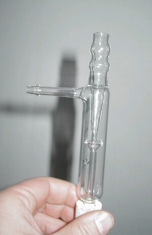
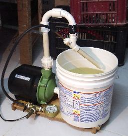
in the smaller space, and makes a "low pressure zone" that sucks in the air.

That's where you want to put the tip of the air pipe.

The low pressure zone will suck little bubbles of air out of the pipe and they will be swept away by the force of the flowing water.

Also, if your drawing is to scale, the air outlet nozzle should be alot smaller to ratio than the water pipe as it is now shown. (smaller equals more suction equals higher flow rate!)

I wish I had paintshop, so I could draw you a picture.

Perhaps someone else could draw one?

axehandle - 29-8-2004 at 16:32

Same principle as bystanders swept away at car races. The nearer to the bystanders, the better. And the higher the car speed the more forcibly will the bystanders be swept away. Same with air molecules near to the water stream. You want a very high velocity water stream, i.e. thinner exit pipe with a "rocket nozzle". Still, I wish someone could refresh Bernouille'e Law to me with a 2x4, I might be able to explain it better then. Couldn't find any better link, only came up with the inane car-race simile, but it might hold water...

[Edited on 2004-8-30 by axehandle]

janger - 29-8-2004 at 19:01

Looking at the design diagram, it would almost work if the vacuum tube was made the water inlet, the water inlet made the vacuum connection, and the water/air exit was constricted slightly.

Try it.

Dave

janger - 29-8-2004 at 21:07

I made mine sort of like this:


I used an irrigation hose t-fitting, and various bits of pvc pipe to get it working. The water goes through the small pipe. In reality this pipe is a larger diameter and connects to the tap, but a small jet is on the end. The vacuum is created on the side inlet.

There was a bit of playing with diameters and positions of the various pieces, but it _does_ work that way. And you may notice it is very similar to your diagram, but with the vacuum/water connections reversed.

mick - 30-8-2004 at 04:29

This is probably obvious
Once you have got all the pipe sizes sorted if you are going to pull a vacuum on sealed kit you will need a non-return ball valve or something to prevent the chance of water sucking back. In a recirculating water pump the water get warm fairly quick, loss of vacuum pulling power and every thing fills with water. To keep the water cool add water+overflow pipe (or add ice). Can get down to about 15 mm Hg with cold water being pumped fast enough which is usually better than an old oil pump. Just thinking, if you could add some gelling agent to the water to reduce the vapour pressure, with the pump you have got you might be able to get below that.
Mick

Tacho - 30-8-2004 at 05:08

I would be very happy with a 200mmhg vacuum. It' enough to boil ethanol at 50ºC (that's my main target) and for vacuum filtrations.

I found this diagram of a venturi (attached), but I can't read what's beside "PVC": Einsotz or Einbotz or something, does that make sense to anyone?


EDIT: OOOPS! I just found out that this topic (homebrew aspirators) has been discussed in the "homebrew aspirator" thread.


Sorry administrators!


[Edited on 30-8-2004 by Tacho]

[Edited on 30-8-2004 by Tacho]

[Edited on 30-8-2004 by Tacho]

venturidiag.jpg - 21kB

mick - 30-8-2004 at 06:13

I had not seen that .
I know this is some where , but a reasonable fish tank diaphragm pump is OK for most filtrations because they do not pull all the solvent off under to much vac. Some do not like acetone and other solvents on the outside though. Low pressure ones can be used to pump air/gas into equipment without worries of over pressurising the kit.
Mick

Hermes_Trismegistus - 30-8-2004 at 07:23

Quote:
Originally posted by Tacho
I would be very happy with a 200mmhg vacuum.
[Edited on 30-8-2004 by Tacho]


I think a vacuum cleaner would supply at least that much vacuum.

Try a Hoover!

vulture - 30-8-2004 at 07:31

A vacuum cleaner cools itself by its airflow. It's going to burn itself down if you get what I mean.

Tacho, the water should flow in a straight line vertically down. You're losing water pressure and velocity in the curve.

The vacuum should be sucked from the side.

EDIT: Merged the threads.

[Edited on 30-8-2004 by vulture]

Hermes_Trismegistus - 30-8-2004 at 07:39

Quote:
Originally posted by vulture
A vacuum cleaner cools itself by its airflow. It's going to burn itself down if you get what I mean.


I was thinking about that actually, before I got my vacuum pump off ebay.

I even picked up an old upright gratis, but never have yet got around to trying it.

I think that it would be possible to use the suction of the vacuum without plugging the nozzle entirely, sorta like a turbocharger uses a wastegate to avoid boom!

If you were to place the smaller intake hose of your vacuum "needs" into the throat of the household vacuum and partially block the hose.....

You'd have a localized low-pressure zone and still a percentage of flow-through to allow cooling.

Still............ it might work better up here than in brazil?

You would definitely want to monitor the heat of the motor with the side of your hand, perhaps it would be like having a vacuum source with a duty-cycle, just like a cheapo stick welder?

Organikum - 30-8-2004 at 08:13

A vacuum cleaner is by no way explosion proof. And needs some air to cool itself.

That will be fun!

Tacho - 30-8-2004 at 08:38

Humm... it's true. A vacuum cleaner might get 200 mmHg... I never thought of that.

But, as Organikum pointed out, ethanol vapours passing through a brush motor would really be fun! A jet engine!

Besides, after spending something like U$60 on that 1/4hp pump, I would feel a pain in the pocket if I could not get any vacuum from it.

Forget vacuum cleaners!

Tacho - 31-8-2004 at 03:55

Mine is a pretty powerfull one and it could only pull 640mmHg.

200mmHg is the maximum I could get with my old refrigerator compressor. Even if my abused vacuum gauge is imprecise, I don't think a vacuum cleaner is of any use in the lab.

Some catalogues say that aspirators could pull down to 25mmHg. That's impresive! Could those delicate glass ones bear such diferential pressure?

Yesterday I built another one using an arrangement of concentric PVC pipes: Failure! I can describe it further if anyone is interested in knowing what NOT to do.

Finally I decided to get scientific and built a test setup, using a huge syringe barrel, stopcorks and different tubes. I cut one end of the barrel so I had this almost transparent tube. It looked like the setup janger pictured (nice picture btw), only it had a stopcork in the bottom too. The vacuum conection was on the side. The water flowed in a straight direction down.

The lower tube had a diameter of about 10mm and the upper one about 7mm. Both could slide in the stopcorks.I tried every relative position possible. I got myself soaked (stopcorks would escape from time to time), but no arrangement I tried gave me more than 650 mmHg. This record was obtained sticking the upper tube halfway inside the lower one.

Look at those glass aspirators! They are so simple! No glassblower could be that careful about distances and diameters! Are you guys sure they can pull that much vacuum? Are you sure its just Bernoilli priciple, I'm having the impression there is some mechanical action, like the water jet stream "carrying" the air bubbles away. I saw this picture of a glass aspirator (in an old Aldrich catalog) where the upper tube was twisted, as if to put some rotation to the water stream.


Hey, Hermes, have I told you that hydrodynamics is extremely complex?

Water Jet Pumps

HRH_Prince_Charles - 31-8-2004 at 07:42

There are 2 configurations: the venturi pump and the jet ejector pump. The former operates more closely to the Bernoulli Effect, but is far less efficient. Anyway, the Bernoulli equation applies to frictionless and incompressible fluids with no turbulence. It is a good approximation in some situations.

Most lab. pumps are of the jet ejector design, which entrains air molecules within the jet.

To get a dynamic pressure drop of 1 atmosphere in water, the Bernoulli equation says you need at least 15 m/s. For a 10 L/s supply, this equates to a nozzle diameter of 3.6 mm. For a nice smooth flow, the jet nozzle should be tapered down to 3.6 mm at a 20 degree angle.

The throat to receive the water jet should be 6 mm diameter with a 45 degree flare at the receiving end. The jet nozzle should be inside the flare but standing off from the throat itself by 4 mm. The throat should be 50 mm long, followed by a gradual widening.

These are partly calculated and partly empirical figures. They agree with frogfot's homemade pump.

Schematic

HRH_Prince_Charles - 31-8-2004 at 07:48

The Water Jet Ejector, dimensions as above

aspirator.jpg - 40kB

Tacho - 31-8-2004 at 08:27

Thanks a lot!

Great information!

I knew there was something very strange with those designs.

I'll do my search in the net, but do you have online (or ftp) references for these pumps?

What frogfot's homemade pump? I searched but could find nothing.

The_Davster - 31-8-2004 at 08:45

This is Frogfot's vaccum pump.

Tacho - 31-8-2004 at 09:03

Wow, I'm speechless!
Thank you again HRH and thank you rogue chemist.

Organikum,

I just managed to install a .rar unpacker in my computer and the material you posted is, as usual, excelent. You deserve to get much more sex than you do now!

Pump Schematic

HRH_Prince_Charles - 31-8-2004 at 09:13

I have a pdf of a research paper on jet ejector pumps somewhere at home. I'll post it if I can find it.

The limiting pressure is the vapour pressure of water - not from Bernoulli's equation but because the vacuum chamber gets wet and outgases at this rate.

Frogfot shows you can do it successfully DIY. His pumping speed is a little less than commercial pumps but his jet nozzle and throat are smaller too. I think, if he increased the dimensions, he would achieve the same pumping speed (typically 67 ml/s = 0.14 cfm).

Hermes_Trismegistus - 31-8-2004 at 11:17

Quote:
Originally posted by Tacho
Mine is a pretty powerfull one and it could only pull 640mmHg.

200mmHg is the maximum I could get with my old refrigerator compressor. Even if my abused vacuum gauge is imprecise, I don't think a vacuum cleaner is of any use in the lab.

Hey, Hermes, have I told you that hydrodynamics is extremely complex?


You're a funny guy tacho, I am glad someone finally put a guage to one of those things, I've always been curious!

EDIT: curious about science...SCIENCE..no more U2U's O.K. guys?

....and Orgi.....I feel sorry for that poor cat of yours!;) I wonder if he'll ever walk again?:D


EDIT: This last joke was made without prior knowledge of chemoleo's black cat thread and now seems a little morbid.:(

[Edited on 1-9-2004 by Hermes_Trismegistus]

Water Jet Pump Design Paper

HRH_Prince_Charles - 31-8-2004 at 14:02

I couldn't find the paper I was after, but I did have this one - where the schematic came from.

Attachment: agricultural jet pump design.pdf (135kB)
This file has been downloaded 9527 times


Faucet adaptor

MadHatter - 31-8-2004 at 14:08

Polverone asked about adapters for faucets to use hydroapsirators. I found my at
Ace Hardware. Goes from a threaded to a barbed end. Works Great !

Tacho - 1-9-2004 at 15:44

Major success!

I built a jet ejector pump folowing the directions given by HRH. What a huge success! My gauge read 20mm Hg (20 Torr) quick! I simply didn't believe it (I still think the gauge is inacurate) so I tested it in a round bottom flask with ethanol, to see if it would boil with my hand's heat. It boiled even at room temperature (about 26°C today)!

It is similar to frogfot pump, since it's made of brass fittings and copper tubes. I attached detailed drawing of it. When I saw frogfot page, I was a bit skeptical, considering my previous failures, but now it's clear that HRH "recipe" works wonders. Thanks for that paper too HRH, ironically it was made in an university near where I live.

Hydrodynamics is extremely complex, but an obtuse mind with obsessive will and a screwdriver can do miracles!

"Ignorance is Power!"(George Orwell, out of context).

EDIT: I just noticed that, in my drawing, I mention 3/4" to 3/8" somewhere. Make that 1/2" to 3/8". Maybe it doesn't make a diference, but the "T" is 1/2", therefore all fittings are 1/2".

[Edited on 2-9-2004 by Tacho]

Attachment: vjetpump.pdf (17kB)
This file has been downloaded 6531 times


possible edit?

Hermes_Trismegistus - 1-9-2004 at 16:07

Quote:
Originally posted by Tacho
Major success!
Hydrodynamics is extremely complex, but an obtuse mind with obsessive will and a screwdriver (and a seven page design pdf complete with performance comparator graphs) can do miracles!


:P:P:P

Performance Measurements

HRH_Prince_Charles - 2-9-2004 at 01:55

Outstanding work, Tacho!

Can you get some performance measurements:

1. Rate of water consumption in litres/minute

2. Pumping speed. (Preferably by measuring the time to evacuate a known volume to a known pressure).

Pumping Speed, S = (V/t)ln(P0/P)

V = volume (cubic metres)
t = time (seconds)
P0 = starting pressure (atmospheric) (Pa)
P = final pressure (Pa)

If you use SI units throughout, you get the speed in cubic metres/second. Convert to litres/minute.

Commercial pumps are typically 4 L/min pumping speed and consume 10 L/min of water.

I

Tacho - 2-9-2004 at 03:33

Well, Hermes... Touché. He, he, he.

HRH,

I'll do my best. First I'll buy a new gauge, I simply don't trust my abused one to give precise measures. 20 Torr is simply too good to be true. I think I can easily measure water consumption and how fast a given volume is brought to a given vacuum.

The only catchy detail in my pump is to make the epoxy exit with a gradual widening. I don't even know if that is crucial or not: Frogfot's doesn't seem to have one. I did mine slowly rotating the tube with the proper inclination while the fluid epoxy set. I used the stepper motor driver I described in an old thread. It was a bit messy and I had to drill away the excess epoxy that cloged the 6,3mm copper tube. Next time I may try some paraffin insert that gets melted away.

Alignment and centralization of the tubes seems to also require care.

frogfot - 2-9-2004 at 03:50

Why is 20 torr "to good to be true"?!?! lol It's easy to get the pressure down to waters vapour pressure.. (I've measured everything with digital lab monometer)

To take away confusion, just wanned to mention that I let the water in the side of the pump, so the nozzle becomes circular (I guess principal is still the same, can anyone calculate on this???)

This was done because I couldn't make it to work the "normal" way (water comes from above).. but now when you've explained the optimal measures it seems obvious why it didn't.. Need more difference between ejector and nozzle throat areas..

Gonna try it the normal way with measures you've suggested!! Didn't know that drilling/enlarging hole in brass nipples was that easy, now these pumps can be really massproduced :)

Btw, is converging part on exit really necessary?

[Edited on 2-9-2004 by frogfot]

Diverging Water Outlet

HRH_Prince_Charles - 2-9-2004 at 04:05

I don't think this is strictly necessary, but it creates a nice streamline flow going into the outlet pipe (if there is one). I think the throat and throat flare dimensions are much more important.

Bunsen's orginal water jet design was configured like yours, Frogfot (with the water entering the main chamber).

Tacho - 3-9-2004 at 00:26

Quote:
Originally posted by frogfot
Why is 20 torr "to good to be true"?!?! lol It's easy to get the pressure down to waters vapour pressure.. (I've measured everything with digital lab monometer)


In my previous attempts, my best vacuum was about 700 Torr (mmHg) so, to see that needle jump all the way down was a weird experience. I'm not used to go from total failure to total success so easy.

Quote:

Gonna try it the normal way with measures you've suggested!! Didn't know that drilling/enlarging hole in brass nipples was that easy


Brass is relatively soft for drilling/machining. Just hold the piece with pliers; if it get stuck, you don't hurt your hand.

Quote:
these pumps can be really massproduced :)


Exactly! I am trying new combinations of fittings and tubings to see what is the easiest way of making it and what does or does not matter.

I already built a new one, with a conical injector and a 7mm diameter, 20mm long exit tube (just a hose adapter with no copper tube soldered), it was a failure! Only about 500 Torr! I'll be testing to see what's to blame, the larger diameter, the shorter length or the conical injector. I have a hunch that the exit tube has to be longer. In fact, I believe the numbers given by HRH are THE numbers, but experiment is the king.

Quote:
Btw, is converging part on exit really necessary?


Good question. Omitting it may save a lot of work. I hope to post my experimental results and pictures/drawings soon.

frogfot - 4-9-2004 at 04:30

Ok, now I understand the excitement, just misunderstood you :)
Tested it the normal way like in your shematic pic but simplified.
And now I see that converging part on nozzle is really important.. first I tested a straight pipe as the nozzle, with ID 3mm, this gave only about 200 torr. However when I changed it to a larger pipe ID 4mm hammered in one end like you've suggested, to ID 3mm (maby slightly larger), this gave 30 torr.. on further addjustement of distance between nozzle and throat it gave 18 torr with suction capacity of 90-100 ml/s (water). At the same time, commercial pump gave 12 torr and ~71ml/s. So, yp, thats too good to be true..

Some measures on mentioned experiment:
Nozzle hole: ~3 mm
Throat ID: 5 mm
Throat length: 20 mm

Btw, any idea how to decrease the end of 10 mm pipe to 3 mm?? It's kinda hard with a hammer.. or maby one have to practice..

[Edited on 4-9-2004 by frogfot]

[Edited on 4-9-2004 by frogfot]

[Edited on 4-9-2004 by frogfot]

Tacho - 4-9-2004 at 17:33

Quote:
Originally posted by frogfot
<snip>

Btw, any idea how to decrease the end of 10 mm pipe to 3 mm?? It's kinda hard with a hammer.. or maby one have to practice..


I doubt it can be done by hammering. It has to be some commercial standart piece. Or resin casting, or even metal casting. As I said, I used this complicated rotating epoxy casting.

New things I learned:
1- The exit tube seems to be extremely important to the workings of the aspirator. No wonder you never see a picture of an aspirator with a short tube. In my second aspirator, the Ø 7mm one, I could get no vacuum at all using the 20mm long fitting alone as the exit. When I added a 150mm flexible plastic tube to its exit, internal Ø 7.5mm, boom, 360 Torr!

By bending this plastic tube with my fingers, I could make the vacuum go even beyond that. So, don’t underestimate this tube, a lot of the magic happens inside it (forget Bernoilli), and I believe the gradual widening is of great help.
I think the straight part of the exit tube (before widening) has to be at least 50mm long

2- From the ones I tested, the best diameters for the injector-nozzle/exit-tube are 4mm/6.3mm. I also found out that the 5mm/7mm was quite better than the 6.3mm/7mm. So a good ratio seems to be 0.6-0.7.

Frogfot, you mention 3-5, that's 0.6.

3- The highest vacuum is when the nozzle is just 1(maybe less) or 2 milimeters away from the throat, and, as frogfot noticed, the nozzle has to be conical, even if just in the tip.

My system (the 1/4HP pump + bucket + my #1 aspirator), circulates 18 liters per minute. It’s a high consumption, but it’s a closed system, and I can’t reduce the pump power (why should I?)

I hope to mount two aspirators in parallel to optimize the use of the pump.

In the average, my pump could bring a 1,64 liter PVC tube “bomb” to 360 Torr in 17 seconds. My math brought me to 4,3 l/s. Thanks for that formula HRH.

EDIT: Oops , make that 4.3 l/minute.

I had an incident when a flake of epoxy clogged the exit tube. Water started to squirt from the vacuum connection. After I cleaned and remounted it, I could not get any vacuum higher than 160 Torr. Some fine tuning may be required, but I won’t bother, this vacuum is more than enough to my purposes. Unfortunately this happened before I installed the new gauge, so I cannot confirm the 20 Torr vacuum.


[Edited on 5-9-2004 by Tacho]

Using mouse balls in one-way valves.

Tacho - 5-9-2004 at 07:57

Don't castrate you pet yet.

The picture shows (in 2, 3 and 4) how to use your computer's old mouse's ball to make a one-way valve. The O-ring makes it even better, although I believe it may work without it. The fittings are PVC. One 1" connection (I don't know their name in english, a short tube with threads inside) and 2 reductions from 1" to 1/2".

An interesting warning: be careful testing this valve with your mouth, the ball seems to jump and can easily go to your thraquea.

About exit tubes of aspirators:

I've changed my 2 aspirator so that it's now identical to my #1 except that it doesn’t have the long external exit tube. I noticed that it could provide as much vacuum as #1, but it had a slow pumping speed. But, if you add a 10cm piece of flexible plastic tube (internal diameter of 7.7mm) to the copper exit tube (picture 1), it gets as good as #1.

So this may be an option to gradual widening: widening in one or more steps using concentrical tubes.

Also, as I suspected, the initial exit tube (6.3mm, copper) has to be long. Mine is 70mm.

In the picture (5 & 6) I also show how I managed to easily center the injector tube in the nipple adaptor using electric tape and epoxy resin. Wind the tape in the tube until it fits tight(5) in the nipple and fill both sides with epoxy.

Frogfot,

I'll add some net or filter to my system. It seem that anything inside the aspirator, even a hair, can change its performace greatly. I have cloggins all the time. 40 Torr is easy to get.


Hermes_Trismegistus - 5-9-2004 at 08:07

Quote:
Originally posted by Tacho
I'll add some net or filter to my system. It seem that anything inside the aspirator, even a hair, can change its performace greatly.


strange....almost like hydrodynamics are complex eh? stilll, I admire your enthusiasm and hopefully, when you're done, I'll get to copy your design.:D

Interesting Posts

HRH_Prince_Charles - 5-9-2004 at 10:03

Thanks for providing such detail Tacho. You shall certainly go to heaven.

I calculate your pumping speed as approx. 0.1 L/s or 6 L/min. (Better than the commercial models).

S = V/t * ln(P0/P1)
= 1.64/17 * ln(1000/360)
= 1.64/17 * 1.02
= 0.099 L/s
~ 100 mL/s
~ 6 L/minute

Tacho - 5-9-2004 at 12:00

Quote:
Originally posted by Hermes_Trismegistus


strange....almost like hydrodynamics are complex eh?


:DLol! That's EXACTLY what I tought!:D

HRH,
There is something wrong with the pressure ratio in your math. I don't think units are important, since its a ratio, but if my final pressure is 360 in Torr (or mmHG), I can't see why the initial pressure should be 1000 instead of 760.

My mistake

HRH_Prince_Charles - 5-9-2004 at 13:19

I was thinking in millibar.

Corrected:

S = 1.64/17 * ln(760/360)
= 1.64/17 * 0.747
= 0.072 L/s
= 72 mL/s
= 4.3 L/minute

An improved Filter-pump

trilobite - 10-9-2004 at 00:09

A few weeks ago I got inspired by this thread, even as there were no practical designs posted, and looked around a bit and found an article describing a bit different water jet pump design. It's from Journal of Chemical Society 123, 3414-3415 (1923) and there is also a design for a laboratory water motor included. both by a guy named Kenneth Claude Devereux Hickman.:)

Improved_Filter-pump.png - 231kB

Vacuum Hose

HRH_Prince_Charles - 10-9-2004 at 13:52

Just some thoughts on vacuum hose. Ideally, the gas conductance of the tubing should be much greater than the pumping speed of the water-jet pump, otherwise it will limit the performance of the pump. Conductance increases with the 4th power of diameter: double the internal diameter and the conductance increases 16 times!

For air at 15 C and 5 mbar pressure and 1 m length hose:

Bore (mm) Conductance (L/s)
5------------------0.043
9------------------0.45
15----------------3.44

Typical water-jet pump pumping speed = 0.075 L/s

For those wishing to get down to 5 mbar with iced water, the hose bore should be at least 9 mm. At higher pressures, conductance increases and narrower bore can be used.

frogfot - 10-9-2004 at 21:44

Nice pics tacho.
If hose diameter limits pumping speed, than would volume of pump do the same? With volume I mean insides of the pump thats filled with air..

Quote:

Frogfot, you mention 3-5, that's 0.6

I always count by area :P

It took some time to to post since I were waiting for silicone in my finall pump to dry.. it did, and after operating for some time darn silicone loosened :( 
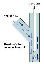
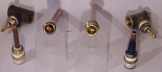
seems like it doesn't like pressure.. or maby i degreased poorly..

Gonna use epoxy next time, but I don't think it's that waterresistant..
Anyway, pump fluctuated at 16-18 torr :cool: This fluctuation may depend (guessing) on the form of the nozzle. I think nozzle should be symmetrical (kinda hard to make this with a hammer)

The specifications of this pump are nearly the same as the one I made before. Only changed pipe to 4 mm ID, hammered to 3 mm in one end.

Tacho, I dunno why you said that throat must be 5 cm long.. Commercial (glass) pump I've got, have ~2,5 cm throat...
Btw, when you refer to HRH, is it "Performance of low-cost ejectors" pdf? well I always assumed it was that file..

Gotta write another text on this pump :o

Dimensions

HRH_Prince_Charles - 11-9-2004 at 01:56

Frogfot, according to the ejector design pdf, the ratio of nozzle to throat diameters should be 0.59. This ratio is critical: throat too small and poor pumping speed; too large and poor vacuum. Kanske possible to compensate for too large a throat by making it longer. Mine is 50 mm length and I don't need a divergent section or hose on the end for it to work well.

In my pump, I have a 6.1 mm bore throat and a 3.5 mm bore nozzle. I fabricated the nozzle from a fine cake decorating nozzle, which was drilled out to 3.5 mm and sawn off. This was epoxied onto some 8.1 mm bore brass tubing. The nozzle has around a 20 degree taper and gives a nice jet. The main housing is a 1/2" BSP female brass T. 1/4" BSP brass reducers are used in each end. I used a countersink drill bit to add a 45 degree flare to the throat (easily cuts soft brass).

When the pump is running, I can pull the nozzle right back from the throat and still get a good vacuum.

Model shops are a good source of brass tubing. My local has 1-10 mm in 1 mm increments.

Don't have a digital camera. I'll see if I can borrow one. Will try and get an accurate vacuum measurement this weekend.

Edit: pumping speed - the hose and the pump chamber will add to the total volume to be evacuated. 1 m of 9 mm bore hose has a volume of 66 cm^3; my pump has an internal volume of around 30 cm^3. So, you have to add 100 cm^3 to the volume of the apparatus.

[Edited on 11-9-2004 by HRH_Prince_Charles]

Tacho - 12-9-2004 at 12:53

Quote:
Originally posted by frogfot
If hose diameter limits pumping speed, than would volume of pump do the same? With volume I mean insides of the pump thats filled with air..


Good question. I don't think so, it's already quite large compared with the hose, but I may be wrong.

Quote:

Gonna use epoxy next time, but I don't think it's that waterresistant..

It's very waterresistant, don't worry.

Quote:

Tacho, I dunno why you said that throat must be 5 cm long.. Commercial (glass) pump I've got, have ~2,5 cm throat...


I mentioned somewhere above that I had much better results when I made that 2cm throat longer. I refer to the tube after the 45° cone, where water exits, before the widening area, is that what you are talking about? maybe we have a misunderstanding and you are talking about the cone itself.
Quote:

Btw, when you refer to HRH, is it "Performance of low-cost ejectors" pdf? well I always assumed it was that file..


HRH is "HRH Prince Charles" our friend here at sciencemadness forum, who choose a user name that's very hard to quote.


By the way, HRH, I use air conditioning copper tubes because they are soft and thick enough to be hammered to shape. I have those model shops brass tubes and they are quite harder to shape.

[Edited on 12-9-2004 by Tacho]

Tubing

HRH_Prince_Charles - 12-9-2004 at 16:19

Yes, I've found brass modelling tube to be quite hard to form too. I don't need to form the tube in my configuration - I used a cake decorating nozzle.

Tinkering today, I found that length of the outlet pipe is important for best vacuum. I have a 6.1 mm bore throat, 55 mm long. Unless it is immersed in water, I need to add a 20 cm tube to the end to ensure good vacuum.

frogfot - 12-9-2004 at 22:36

Haha, oops, sorry HRH :o:P;)

I've tried hammer aluminium tubes. They're easy to form, but it's hard to make nozzle symmetrical..

Quote:

I refer to the tube after the 45° cone, where water exits, before the widening area, is that what you are talking about?

Yp, we're on the same thing..

piece of shit aspirator

cavgdad - 14-9-2004 at 12:34

i bout this from macnanbio on ebay
http://cgi.ebay.com/ws/eBayISAPI.dll?ViewItem&category=2...

it states that it does 38 mmHg, but when i use it on distilling equiptment it only boils H2O at 80C thats somewhere around 350mmHg right. so is there anything I can do to make it work or should I send it back?

Crap aspirator

HRH_Prince_Charles - 14-9-2004 at 13:12

cavgdad, just checked out the ebay page. It specifies 38.25 inches mercury (negative gauge pressure) - this is impossible - maybe it is a typo for 28.25 inches Hg negative gauge = 5.6 mbar absolute. This is the vapour pressure of water at zero degrees Celsius, so they are saying the pump reaches water vapour pressure, as it should.

Your water is probably warmer than this, but you should get down to 25 mbar or so.

First thing: is your water pressure high enough? If you don't get high enough water speed through the pump, its minimum pressure won't be as good.

Secondly, try it with the aspirator outlet under water, or stick a hose on it - this works for me.

Thirdly, keep the water as cool as possible. Best is to recirculate ice water with a pump. You'll need a high pressure pump though (50 foot head or better in US units).

Hope this helps.

Tacho - 15-9-2004 at 03:14

Quote:
Originally posted by HRH_Prince_Charles
<snip>
Secondly, try it with the aspirator outlet under water, or stick a hose on it - this works for me.

Thirdly, keep the water as cool as possible. Best is to recirculate ice water with a pump. You'll need a high pressure pump though (50 foot head or better in US units).

Hope this helps.


If you put the aspirator outlet under water, remember to use some sort of protection agaist suckback or, when you turn off the water source, your sistem will suck water until pressures equalize or you water reservoir reaches the outlet level.

My 1/4hp pump is rated 15 meters, that's about 50 feet. It works perfectly, confirming what HRH said.

Pump Size

HRH_Prince_Charles - 15-9-2004 at 07:11

That 1/4 hp pump sounds almost perfect Tacho. I've looked everywhere, and the best I could get was a 370 W model. It does give 25 L/min at 15 m head, so I could run a pair of water jet pumps.

A typical water-jet pump only requires around 30 W of power to run! (calculate from pressure drop x flowrate). However, a typical pump is only 20% efficient at driving the water - the other 80% goes into heating the water in the pump. So, to get 30 W of water power for the water jet, you need a pump of

100/20 x 30 W = 150 W (0.2 HP)

Note also that the maximum head for a pump is at zero flowrate. In use, the head will be lower. My pump is 35 m max. head but only 15 m head at 25 L/min.

frogfot - 15-9-2004 at 12:22

I'm currently looking for a cheap water pump to make a recirculating station too.. but I'm worrying about sound. Which pumps make less sound, usual or "immerseable"?

Btw, finally wrote some specifications on my little respirator.
It gives about 3 torr higher than commercial pump, but on the bright side it sucks 1,39 times faster with only 1,02 times greater water consumption :cool:

Excellent Details Frogfot

HRH_Prince_Charles - 15-9-2004 at 17:08

Your pressures seem as close as to make no difference. I've noticed the pump pressure seems to increase slightly after running for a short period.

From a heating point of view, external pumps are better: waste heat from the motor doesn't heat the water. Considering that most pumps are so inefficient, this doesn't make that much difference: it would be better to get an ideally rated pump.

Anyway, this time of year, what does a viking have to worry about? Snart comes the snow and then shall you have unlimited cooling. Can't you just pick up a bargain from Clas Ohlson or something? You boys are spoilt for choice.

Edit: I mean pump pressure falls slightly after a while running.

[Edited on 16-9-2004 by HRH_Prince_Charles]

Edit again: oh yeh, as to noise - can't see it makes any difference. Placing my external pump on foam certainly cut down vibration.

[Edited on 16-9-2004 by HRH_Prince_Charles]

frogfot - 15-9-2004 at 22:04

Ok, then external pump it will be :)

Quote:

Can't you just pick up a bargain from Clas Ohlson or something? You boys are spoilt for choice.

Hehe, there are a large choice, but not with prices :o
I had my eye on one of the cheapest pumps which is 0,5hk, 40litre/min(max), 35m(max height). Thats for 60$, but I hope there will come up something on second-hand market..

Tacho - 16-9-2004 at 03:22

Congratulations frogfot, your (beautifull) page will certaily become a reference for those willing to built their own aspirators! Great work! Fell free to use any information or pictures I posted, although your work is more than comprehensive.

About pumps and silence: Before I bought this pump, I had another one that's very popular here because it's very cheap, even being 1/2hp. It's a "vibratory" submersible pump. I could not use it, because it's tremendously noisy. Good for wells or underground reservoirs, but nothing else. My new pump is very silent.

Another note: my water is above 20ºC 99% of the year, that's a good reason for my higher pressure readings.

Centimeter - 16-9-2004 at 18:04

I wish I had seen this bit about pumps before I whent and purchased one. I purchased this one http://cgi.ebay.com/ws/eBayISAPI.dll?ViewItem&rd=1&i...
It says its maximum height is 6.5 feat, so I am guessing it will not be good enough. Is there some way I can render this pump usable or do I just have to get another one? What kind of pump has the desirable specifications? I don't think any gardening or aquarium pump is going to have 50meter head capability. How much money are we talking here? I only need the pump to pull about 200 torr but I sure would love to be able to experiment with ones that can pull less than 20 torr.

Edit- I have this thing that attaches to my faucet and it is sapost to be used to run water from the tap to my fish tanks. However when the water is allowed to flow through the system it acts exactly like an aspirator. I decided to try and measure its abilties. I found that it was able to easily lift water up ~7ft. The ID of the toob was 3/8" thus I calculate that it drew up about 152ml of water at 15*C. The internet says the local pressure is 1017hPa. Now using this information I know that I should be able to figure out how many torr the aspirator is capable of pulling, however I don't remeber how and my notes are entirely confusing. My school chem book is no help either. Can someone please show me how to calculate the vacuum's pressure? I suspect it is around 500 torr as it is able to pull about the same as I am with my mouth and I found a site that said the human mouth can pull a vacuum of 20 inches of mercury.

[Edited on 17-9-2004 by Centimeter]

neutrino - 17-9-2004 at 13:04

The diameter of the tube doesn't matter. Convert that to mm and divide by the density of mercury (13.6) and yeu get 157mm. 763mm (your air pressure)-157 = 606mm Hg. Not really that good.

Tacho - 17-9-2004 at 16:13

Centimeter,
Considering what I have learned so far, I believe it’s possible that you can built an aspirator that gets 200 torr out of your pump. However, I don't think it will be easy, and you will have to test designs and that takes time, money and patience. I would start with the model described in frogfot's page to see how it behaves. With some fine tuning, like trying different distances from nozzle to throat, you may get a useful vacuum.

I see neutrino has already answered about the pressure calculations, but I had written this text and will post it anyway:

Volume has nothing to do with it. If your aspirator pulled water 7ft high, it could have pulled mercury 157mm high. Since atmospheric pressure is about 760mmHg, your vacuum was 760-157=603mmHg. That’s about… hummm… 603 torr.

By the way everybody: The one-way sphere valve I described, using a mouse ball, is excellent. Much better than my previous small steel sphere one. It has been holding a 300 torr vacuum in a PVC setup that has over 3 liters for over an hour! The only hard-to-find piece is the rubber o-ring, but it may work without it, since the ball seems to be covered with rubber anyway.

Achievable Pressure

HRH_Prince_Charles - 18-9-2004 at 06:06

The thing that governs the limiting pressure of the water-jet pump is the velocity of the water jet.

15 m/s gives a negative pressure of around 1000 mbar.

The problem with your water pump,cm, is that it doesn't have enough pressure to give a high speed jet. You'll get some pressure reduction, but not much.

A vacuumstat.

Tacho - 30-9-2004 at 15:31

I stripped my old vacuum gauge and connected the bourdon tube to a microswitch, using a brass lever. Now I can automatically keep my vaccum in a given range. The maximum is adjusted turning the screw. I adjusted it to to turn off the pump at 140 Torr and it turns it back on when vacuum falls to 220 Torr.

Works marvelously (sp?).

Note: the switch I used was in my scrapbox and is turned off when pressed, not when released.


Mendeleev - 30-9-2004 at 15:37

What is the general sucking capacity of a typical aspirator? I realize the vacuum strength is just a little over the vapor pressure of whatever liquid you are pumping through it, but how about capacity? Could an aspirator evacuate a 2 L container? I ask because mine pulled a 733 mm vacuum when connected directly to the pressure gauge running water from the tap, but when I hooked it up to a 1L flask equiped with pressure gauge it managed to do about 620, with a brief spike to 700. What's the problem?

Tacho - 1-10-2004 at 03:08

Bottomline:
If you have a one-way-valve, try turning the pump off than on again.

Making a short story long:
When I turn on my vacuum station, pressure goes down to about 560mm (my vacuum gauge reads like yours) and stops there. I turn off the pump manually and wait until all water "falls" from the aspirators (glob-glob-glurrp sound). The ball-one-way-valve holds the vacuum (the white cilinder at the right of my last picture). When I turn the pump back on, vacuum goes quickly to 620, where the vacuumstat turns it off automatically.

I don't know why this happens, hydrodynamics is extremely complex! :D*lol*

The rest of the information you seek can be found in other posts in this thread.

Wish you luck.

Typical Aspirator

HRH_Prince_Charles - 1-10-2004 at 15:27

Mendeleev:

The typical pumping speed of a lab. water-jet pump is 67 ml/s or 0.15 cfm.

The pressure falls exponentially. To evacuate a 2L flask down to 20 mbar from atmospheric will take 5 minutes or so.

You either have some instability in your pump or a leak - possibly the latter.

Mendeleev - 2-10-2004 at 10:04

There were no leaks in the aspirator itself because it is a very nice glass aspirator I bought for $9 from an ebay store. I am guessing, I just had crappy hose connections, because when I set up the apparatus again, it managed to pull 700 mm consistently from a 1 L flask, but would not go 1 mm more despite running for 3 minutes. I am fairly pleased with 700 mm Hg vacuum, but where did those other 33 mm go?

Ultimate Pressure

HRH_Prince_Charles - 2-10-2004 at 11:09

How good is your vacuum gauge?

Another way to measure the pressure is to evacuate a small flask with some water in and see at what temperature the water boils.

Are you running the aspirator from a tap or a pump?

Mendeleev - 2-10-2004 at 15:46

My pressure gauge is pretty good, and I am running cold tap water, I was thinking of getting a bilge pump and pumping ethylene glycol through it, but I don't know if a bilge pump could handle it, I think ethylene glycol is a lot more viscous.

Oxydro - 3-10-2004 at 06:49

Someone should try running steam through their (homebuilt, maybe) aspirator, and see what can be achieved. I did a highschool science fair project a couple of years back that was a design for a solar powered air conditioner, it used solar-generated steam to power a steam ejector, making a vacuum that made water evaporate faster, absorbing heat. I discovered that it wasn't practical, BTW, but at least the idea got me to nationals.

A steam ejector is like a aspirator, except that it is powered by a jet of steam instead of water. The theoretical pressure limit is lower, because, like in a diffusion pump, the vapor is jetted out fast enough that it doesn't escape into the vacuum line for the most part.

I wish I still had the one I used, it was quite a design. Solid titanium, it was a rectangular block that had been drilled out to shape, very precise. Unfortunately, I had to give it back to my brother, he had got it via Honeywell, who he used to do design work for (sensors for pulp&paper mills).

Edited for spelling

[Edited on 3-10-2004 by Oxydro]

Tacho - 3-10-2004 at 14:06

Sorry Mendeleev, I did not read your post carefully. I realize now you are working with tap water, so my sugestion makes no sense.

The probable reason for the problem I described above is the air bubbles that get trapped in the water that circulates in a pumping station. A larger baffle may solve that problem.

Tacho - 13-10-2005 at 12:57

A bit of information for future vacuum station builders: I tried to use a dishwasher pump and the results were lousy. Only 550mmHg with very small pumping speed.

I don't know the exact power of the pump, but it seems pretty heavy duty and I estimate about 100W.

That's a shame, because the whole station was very light and portable.

Twospoons - 13-10-2005 at 15:48

If the pump had a shaded pole motor (very likely) then I'm not surprised. The ones we used on clothes washers pulled 90W electrical, but only put out about 8W hydraulic. Appalling efficiency, but they were dirt cheap.

Sump pump

mericad193724 - 10-9-2006 at 16:23

sorry to dig up this old thread, but I have been working on a "water aspirator pumping station."

I made the aspirator by using frogfot and tacho's method. I am using an old rusty sump pump, the kind that pumps water out of your basement to prevent flooding or damage to the structure. It is pretty powerful, but I am not sure if these things are designed for continuous operation. Is it ok to have one of these running continuously for an hour or so, while I do distillation?

Another thing is should I be worried about overheating, the pump will be about half way in the water (heat sink) but have noticed it being hot to the touch even then.

thanks.

Mericad

Mr_Benito_Mussolini - 11-9-2006 at 15:29

Anything robust enough to pump out your basement should be robust enough to run for an hour or so. I don't know the exact cooling mechanism of your bilge pump, but the ones I have seen can draw water down to a depth of less than an inch and don't need to be fully submerged.

Remember, the power needed for a typical water-jet pump is low - less than 100 W. You need a head of say 15 m and a pumping speed of say 15 L/min. If the pump is too powerful, you will dump too much heat into the water and [edit] raise the limiting pressure of the water-jet pump.

[Edited on 11-9-2006 by Mr_Benito_Mussolini]

Tacho - 12-9-2006 at 03:36

Basically what you are asking is "will my X pump handle it?". I don't think anyone can answer that.

But what the Duce posts is true. You don't need much power to make the typical water-jet pump work. Maybe you should consider a by-pass to release some pressure and not stress the pump. Or use more than one aspirator in parallel.

sorry to reawaken an ancheint thread

niertap - 2-2-2012 at 23:01

... however I once made one


I took a little plastic hose adapter, then flattened the edge while heating it.

I cut off one arm of a t connector, then shoved it in as hard as i could and tightly wrapped it in parafilm.

It worked alright. i think what's important is that the water entrance and exit are about the same size. I don't think the vac part has to touch the water, just be in a sealed chamber with entrance and exit for water being roughly equal.

yet another aspirator

matjazv - 16-7-2012 at 04:23

Thanks almost exclusively to info in this thread, I also made one yesterday.
mv_aspirator_plan.jpg - 112kB mv_aspirator_photo.jpg - 37kB

Notes:
Brass tubing, copper tubing + drilled endcaps, all metal connections soldered (Ag/Sn). The 4mm OD orifice was centered inside the 5mm ID tube with a bit of thin copper wire, then soldered. Orifice/exhaust ID ratio is 0.6 exactly. The conical jet receiver is made of FIMO clay (the type that you bake in a kitchen oven to harden). The bottom endcap was not pushed all the way onto the copper tubing, so that the clay can grab it better. A standard garden hose (not shown) fits over the top part and gets clamped with a nylon tie or some wire, just below the endcap. Clear PVC hose at exit end made all the difference: not even 500mbar without that.

Performance:
Feels very sturdy. Took some 30 seconds of pumping a 320ml jar until my cheapo vacuum gauge landed all the way down at zero. A spoon of water in the jar started bubbling after heating the jar bottom with my hand. 50mbar?

Thank you all for the key points! This one will be used for flash pickling of food. Yummy. :)


[Edited on 16-7-2012 by matjazv]