Sciencemadness Discussion Board

The Synthesis of Sulfur Trioxide and Oleum: the vanadium (V) oxide-catalyzed method

Fleaker - 3-8-2007 at 21:24

(Note: Yes, it's about time, I know. I promised this a long while back and my lab partner and I just finally got to it. Before going to prepublication for strenuous review/criticism, NERV and I decided to put it here until we've finished the work. Let us emphasize that this first lot of pictures and tests are merely proof of concept--that our catalyst works and it's feasible on a small scale. For now it will be written in a colloquial style, and will then be brought up to the standards of proper scientific discourse. Only then will it be in prepublication for your review.)

Now, for your enjoyment, Fleaker and NERV's first foray into the much anticipated synthesis of your friend and ours, sulfur trioxide!


While Garage chemist's method is admirable, it is limited to small scale use as the persulfate is relatively expensive. It also requires high temperatures and is hazardous as well. Sulfur trioxide is extremely aggressive at high temperatures and will attack most all things organic. It forms thick, corrosive acid fogs that can blind or cause pulmonary edema. However, us lot on SMDB are not timid chemists, we know what we're up against and what we're after :) That's why you're reading this ;)

Since this was a test, no special effort was made to include flow meters on both ends. This was a basic test just to check for catalytic activity. In fact, it was more of a "hey, do you have free time today? Oh, so do I! Excellent, shall we meet up and see if we can make some sulfur trioxide in a improvised setup?" Despite the impromptu decision, today's results were encouraging.

As garage chemist noted, oleum is very useful stuff for organic synthesis, and I can't even begin to list all of the interesting things one could do with it. Sadly, it's expensive and rather hard to find thus explaining our impasse.

Alright, onto the science:

Sulfuric acid is used in many industrial processes and is one of the most produced chemicals in the world. Current industrial production of sulfuric acid is based upon these reactions occurring between 400-700 degrees Celsius:

S(s) + O2(g) → SO2(g)

2 SO2 + O2(g) → 2 SO3(g) (in presence of V2O5)

H2SO4(l) + SO3 → H2S2O7(l)

which is then diluted with water:
H2S2O7(l) + H2O(l) → 2 H2SO4(l)

In this first proof-of-concept run, we cheated. We did not start from sulfur; instead we used anhydrous sulfur dioxide stored as a liquid in a lecture bottle. Our fume hood's compressed air line was used as the source of oxygen for the process. This was done out of convenience.

Reagents utilized:
(1) lecture bottle of SO2
500mL ACS pyridine (to test for SO2)
compressed air
120mL 17.4M ammonia solution
15g technical grade (old) vanadium pentoxide
1g potassium sulfate (hydrated)
10mL dH20
Glassware and miscellanea:
10mL beaker
250mL beaker
glass stir rod
large porcelain evaporating dish
large stand with cast iron ring
Meker and Tiril burners
Forceps and tongs
Mullite fiber (kaowool)

Apparatus/reaction tube was constructed from:
(1) 55 (edit) centimeter segment of 2.54 cm diameter stainless 316 Swagelock brand tubing. All fittings were flanged stainless and reduced from 1 inch/2.54 cm to 0.25"/0.635cm. No valves were used. A glass wye was used to connect the pressurized air supply with the SO2 cylinder. Both gases mixed in a neoprene tube (input) which fitted over a stainless barbed adapter and injected into the packed tube. The reaction vessel was housed in a 1200 deg. Celsius tube furnace.

Output was a Silex brand high temperature silicone tube that was friction-connected with a twist of copper wire. The output temperature was measured with a thermocouple. The output gas product went into a measured volume of water, hopefully reacting with the water to form H2SO4.


Catalyst Preparation
The amounts used in this preparation were empirical (i.e. V2O5 was added to ammonia solution until it would no longer dissolve). 15g of orange V2O5 was added with stirring to 120mL of concentrated ammonia water forming a yellow solution of ammonium vanadate. A small amount remained undissolved. To this turbid solution, 1g of potassium sulfate was added.

About 30 grams of 1/2" (1.25 cm) Kaowool fiber blanket were shredded into small pieces and placed in a large evaporating dish. The solution was then poured over top and worked into the mullite substrate with gloved hands, thoroughly coating each piece. These pieces were then picked up in forceps and heated to decompose the metavanadate.


The pyrolysis and subsequent loss of ammonia occurring as follows:
2 NH4VO3 → V2O5(s) + 2 NH3 + H2O at approximately 220 deg. Celsius.

Having both limited time and patience, we heated the material at a much higher temperature with two different methods: direct heating via the flame of a methane-fired Tiril burner, and indirectly by heating the evaporating dish with the catalyst and substrate to 700 deg. Celsius (red incandescence). A half of the catalyst was heated via the former method, a half by the latter. In both cases, it took several minutes of strong heating to remove the ammonia and decompose the yellow ammonium metavanadate to the red colour, vanadium pentoxide. On pieces heated directly, there was carbonization.* On pieces heated indirectly, there was melting of the V2O5 which formed a red-brown glaze on the porcelain.


The conversion is complete upon loss of ammonia and conversion to a red-brown covered woolly mass.


(that red material is V2O5 that melted and glazed itself onto the porcelain)


The following are pictures of the test setup.


(The whole apparatus)


(the sulfur dioxide cylinder)


Experimental: Observations and Qualitative Analysis

The reaction tube was loaded with the catalyst. In fact, it was so packed that it was difficult for me to blow air through the tube. We had the tube furnace preheating while we made the catalyst, so when we put the cold reaction tube in, the temperature dropped. We plugged both ends of the tube furnace with more kaowool to act as insulation. Being low on time (we were both very hungry), I thought it was a good idea to kick up the temperature by another 100 Celsius from 550 to 650 degrees. We then proceeded to connect the hoses and turned on the compressed air to get a sense of how much to flow through (measured by the rate of bubbles in the 250mL graduated cylinder on the output side).

While I watched the output, NERV adjusted the gas flow. We guesstimated that we needed about 2.5X the volume of air to SO2 (assuming 20% atmospheric O2 and no competing side reactions like NOx formation). During the air flow-through at 660 deg. Celsius, we noticed a goodly amount of steam exiting through the output (which was not submerged at this point). Realizing that we had made a mistake and had not dehydrated the catalyst enough, we let the air continue to run to remove any moisture still left in the tube**.

The Silex tubing was rated to 280 deg. Celsius, and it was holding up remarkably well***. Using the thermocouple, a peak temperature during flow through of 167*C was obtained. This was due to heat dissipation from the air flowing through the stainless, since the metal itself does not conduct heat very well.


After we opened the the sulfur dioxide bottle, we saw very little for the first minute or so, then immediately a dense, thick fog was noted, as thick as anything dry ice could produce. I licked my finger and gave a swirl in the fog. I tasted it and it was very sour. This opaque mist was apparently much denser than air: it overflowed the graduated cylinder and onto the epoxy counter tops where the lower hood baffle removed it. Like us, you are now probably wondering if it is sulfur dioxide/sulfurous acid mix. We have an answer: at various intervals we used pyridine on a Kimwipe to test for the presence of sulfur dioxide. Any sulfur dioxide and the pyridine soaked paper will turn a nice yellow colour. In no case did we see any yellow colour until we tried with pure SO2 from the bottle.

(Just the bottle: next time we'll be sure to get a shot of the yellow complex formed. No complaining--I had to smell pyridine, whose odour I HATE and NERV adores :o)


Right before we called it quits, the reaction of the water and the output gases became extremely violent and almost boiled over. It was at that point when we noticed that our tubing had become very very hot (we burned ourselves in our haste to pull it out of the cylinder to prevent an overflow) and had been severely corroded by the vapors passing through the tube. We turned off the furnace and let the air continue to run.


As soon as is convenient, I hope to precipitate any barium sulfate and sulfite and then to test the residue with XRD to confirm sulfate presence. When we run again on Monday, we will bubble the SO3 into some barium hydroxide solution.

We preserved a sample of the ''sulfuric acid'':


(The cylinder with bubbling tube removed, this is post reaction, most of the mist was gone.)

What went wrong, and the lessons learned:
*This carbonization probably rendered some of the catalyst inert. Pity. Oh, by the way, V2O5 melts to a nice red-brown liquid at red heat :P
**However, we foolishly forgot to recall that our compressed air source was full of humidity. Once the reaction was underway, this produced a sulfuric acid fog and probably ruined some of the catalyst. Utterly stupid of us not to put a drying tube in there. Effectively killed yields in an otherwise efficient reaction.

***That is until the sulfur trioxide came over. Residual moisture in the tube and the acid mist formed (see above note) charring the silicone tubing. The heat formed was intense, the reaction tube must have really warmed up, I observed a 5 deg. Celsius raise in temperature on the digital display while the thermocouple (touched against the Silex) indicated a 100 degree rise!! To us, it seemed that the reaction was that of the SO3 and any water (along with the silicone).

**Have pH meter on hand, more analytical equipment etc.

Conclusions:
We probably made sulfur trioxide. Definitely, need more qualitative tests. I am rather convinced. Whatever was produced almost ate through the tubing and was getting quite violent towards the end. Probably should have used some schlenckware and massed it out and filled with H2SO4 and got a mass difference (making H2SO7). Whoops. We'll give that a shot next time.

Much more to come! This is just the start. Soon we will have a working sulfur burner, but before that, we hope to have a better prepared catalyst and a more quantitative system setup with flow meters for more precise reactant control. It will be less of an improvised set up. However, today's work confirmed the production of SO3, how much of it is unknown. Next week's installation should peg that down. I, Fleaker, am still busy with some other work (which may pop up in General Chemistry)

Unfortunately, NERV has an even tighter schedule than I do, his free time being relegated to Fridays. Quite unfortunate.


We just hope that we can make this method somewhat viable for the hobbyist. This is obviously a technochemistry project, but we believe it can be made to work on the cheap with modifications.

As always, feel free to U2U us, we're keen to hear thoughts and suggestions. And yes, when we're churning out large quantities of oleum, there will be some made available to our chemistry confederates. If all goes well, NERV and I would like to post on thionyl chloride and other compounds synthesized with oleum.

Best regards,

Fleaker & NERV


As an ending note, please excuse misspellings, typos, and grammatical clumsiness. It is late and I am tired and if it's glaring or you can't understand something, don't clog up the thread, U2U me and I'll fix it. Thanks.

For reference:
US patents No. 4285927 and 4539309 which we cite as source of information.

[Edited on 4-8-2007 by Fleaker]

[Edited on 4-8-2007 by Fleaker]

Sauron - 4-8-2007 at 05:30

I'll follow your progress with rapt attention, as I have a 2" ID x 12" tube furnace, and a supply of V2O5 on hand.

SO2 is restricted here, so I'll have to make and liquify mine own and load it into sample cylinder w/valve.

garage chemist - 4-8-2007 at 05:54

Great documentation, I like it!
One thing: a little moisture in the air that is mixed with the SO2 is usually of no concern, since the temperature in the catalyst tube is above the boiling point of H2SO4. I just means some SO3 comes out as H2SO4 vapor, which means slightly reduced yield when SO3 is the desired product.

And you should definately lead the output gases into conc H2SO4 and not into water. Gaseous SO3 just forms a H2SO4 fog, and the absorption is very bad.
If you use conc H2SO4, you can distill the SO3 out of it afterwards and therefore directly weigh the amount of SO3 you made.

It is usually impossible to completely convert SO2 into SO3 with only one catalyst tube. Why your pyridine test for SO2 was negative I do not know.

Otherwise, great work! I plan on trying this as well with my tube furnace whose quartz working tube should arrive soon.
Unfortunately I only have a small amount of vanadium compound (ammonium vanadate).
I might try using perlite as carrier for the catalyst, do you think that could work?

BromicAcid - 4-8-2007 at 06:15

Excellent! Great to see nice documentation on a matter so dear to our hearts, these are the kinds of threads I really love to see around here, good luck!

The sulfur burner that you intend to make seems to be one of the sticking points, I remember AxeHandle had quite some difficulty with it (and never got a satisfactory one), though there were some good ideas in that thread.

Fleaker - 4-8-2007 at 08:44

Thanks all of for your replies. Not_important U2U'ed me last night and I caught it this morning, his advice on lowering the temperature and using a different substrate was in line with what the patents had suggested. I used this mullite fiber blanket because I had a lot of it on hand (I sell kaowool, great material for furnace building, and passable as a substrate). I'll probably go to the pool supply later today and get some diatomaceous earth. During the catalyst preparation and after we packed it into the stainless tube, we noted one problem with it: kaowool insulates too well, even when wet with ammonia. This made it very difficult to decompose the ammonium vanadate completely and moreover, it seems now very likely that the decomposition water was reabsorbed by the kaowool. We saw water vapour coming out of the line when we did our initial flow through of air.


@garage chemist, both NERV and I can say that any sulfuric acid mist produced is troublesome. Your method will definitely be used in subsequent runs. Your earlier work with the persulfate route inspired us to look for a cheaper way. I do not know why we did not see more SO2 using the pyridine test. Although our tube was filled with quite a bit of catalyst, it could not have been that efficient. My only speculation would be that SO2 was forming sulfurous acid from residual water left in the Silex tube. With respect to perlite, that is a good idea. Now I'm curious. The only problem I see is that it has less surface area than silica or diatoms and also, it insulates too well. I think a conductive yet porous catalyst is what is needed.

So, on the agenda now are:

a.) a working sulfur burner (and no, we're not too proud to ask for plans, tips, and advice--Sauron maybe?)
b.) a better stainless set up, valves
c.) flow meters for air, SO2 consumptions and subsequent maths involved.
d.) Use pre-dried air! I'm thinking 18M sulfuric acid gas bubbler for the pre-dry.
e.) analytical testing for SO3 produced (perhaps saturate 80% n-propanol water then titrate with barium chloride. I'd have to find a suitable indicator)
f.) collect SO3 into H2SO4 as recommended by garage chemist, distill for mass and yield.

I can get sulfur dioxide easily and relatively cheaply (in large cylinders, not in these convenient lecture bottles), but sulfur is still cheaper. As simple as going to the garden supply, buying a 25 kilo sack for $15. In designing a sulfur burner, I recall my experience designing oil fired furnaces and building my own oil burners. Why? Oil is hard to burn, it also must be hot to make it fluid enough to go through the orifice and be atomised. I plan on having a reservoir for the sulfur and keep that heated electrically at 130 deg. Celsius. That (at reasonable temperatures) is when it is at its most viscous. Then I would draw it into a burning chamber with compressed air, using a venturi effect to siphon the sulfur from its melting pot.

I am fairly certain that I must use a propane preheated furnace (to say 550 deg. Celsius) for it to burn and not just spray on the refractory walls. In order to recover the sulfur dioxide and scrub out any sulfur particulate, I would need a flue which is lined with some material that the sulfur could condense upon (perhaps Kaowool? :P ). The flue is then connected to a tee which is connected to a dry air supply and then the catalyst tube. Seems like a lot of work, doesn't it? I have a furnace and a burner designed to run like this, so it's a simple modification of buying some PFA tube to run the sulfur in. Building the flue and sulfur scrubber will take some time though, and I can't promise to have it done before September.


Regards,

Fleaker

Eclectic - 4-8-2007 at 08:59

You might try 1/8" bead activated alumina, silica gel, or even molecular sieves as the V2O5 carrier. You should get much better flow through the catalyst bed. Also, why not use pure welding grade O2 from a tank? The cost should be more than offset by advantage of not having to deal with all that excess N2 blowing your product out of the condenser. You could lease a tank, use it up, and return it before 30 days and avoid monthly tank rental.

For a sulfur burner, how about a small jet of O2 burning in vaporized sulfur and impinging on a molten sulfur pool, followed by an afterburner to complete combustion with excess O2 and feed directly to the catalyst bed? (There may be process control and excess heating issues. :o )

Fleaker - 4-8-2007 at 10:10

O2 is somewhat expensive I suppose, but I agree that it would boost conversion efficiency and prolong catalyst life. For a sulfur burner using that, I think it would greatly help, but it would be an intense reaction, very high heat being produced. That would mean SO2 produced would react to SO3. That mixture would then be passed into the V2O5 bed. That's a good idea, more efficient. I believe my sulfur burner is more suited to bulk production. If it goes anything like burning waste vegetable oil (in terms of flow rate), then it will probably be burned about 5.5L/hour!! That's quite a bit of sulfur. Of course that 's running full out, flow could be adjusted by the velocity of the air being put through the tubes. :)

I know I do not want to use perlite because it is too insulating, and kaowool we will only use to hold our other substrate in the catalyst tube (picture plugs at each end). Inside that I want to use diatomaceous earth with V2O5 and K2SO4 on it, and perhaps I'll give it a shot with zeolite, even though they are expensive and diatomaceous earth would work just as well. I don't know if it's speculation on whether or not they would improve flow rates--to me, it would seem just as bad as a tube stuffed with kaowool.

The_Davster - 4-8-2007 at 10:55

*remembers my unused resistance wire and couple hundred grams of V2O5*
...hmmm....

Anyway, great work, I was worried when I did not see this in prepub today, until I found it elsewhere. I have always wanted to try to do this, but less than stellar ventilation prevents this. I look forward to following the progress of this!

Eclectic - 4-8-2007 at 11:02

I have a book on H2SO4 manufacture that indicates that the catalyst is V2O5 in molten K2SO4, or better, Cs2SO4. I'd be worried that a powdered catalyst might compact and block the tube. Any beaded desiccant should work as a carrier that would guarantee free flow paths through the bed. Silca gel beaded kitty litter, activated alumina drier for compressed air, used mol. sieve beads, etc.


Studies also indicated that dry V2O5 on a carrier did not work well, a molten K2, Rb2, or Cs2, SO4 salt is needed as a promoter.

[Edited on 8-4-2007 by Eclectic]

The_Davster - 4-8-2007 at 11:34

I wonder if one could make an ammonium vanadate solution, and then use that for addition to a hot alumium tri-sec-butoxide(or other alkoxide) producing, after calcining, V2O5 doped alumina sol-gel with very high surface area? Before calcining the gel could be absorbed onto porous material, like molecular sieves, and then calcined hopefully giving a loose mix of ultra high surface area vanadium catalyst.

Hmm I just may make something like that for kicks, and to motivate me to at some point try to make oleum myself.

Magpie - 4-8-2007 at 11:40

Nice going Fleaker and NERV! I agree with Bromic that it is indeed nice to see a full development project with pictures and all the details. Although I am not familiar with all the possible uses of SO3 just the mention of thionyl chloride has got me salivating. ;)

I think your use of commercial liquified SO2 and the possible use of compressed O2 sound like the way to go initially as you go after optimizing the heart of the project, which has to be the catalytic converter. When the main issues there are resolved you can always go after the feed streams to optimize the system for OTC.

It does sound like beads of some optimum diameter would be good for both heat transfer and uniform gas flow through the tube. If the V2O5 could be incorporated right into a porous bead that would seem to be ideal.

I like the looks of your new hood. ;) Is this the one you and NERV have built? If so I'd like to know the details, perhaps in another thread. It looks pretty wide.

I'm glad you are taking such good care of NERV. Please don't forget his daily 4PM feeding of pyridine. :D

Sauron - 4-8-2007 at 21:17

As I see it, the main technical problem is that the SO3 will emerge from the tube reactor quite hot and the dissolution of SO3 in H2SO4 (even anhydrous acid) is also quite exothermic so what is needed is a recirculating loop of H2SO4 and efficient heat exchanger to remove all that heat. Otherwise you will just have SO3 distilling out of the oleum about as fast as it is created. I think only a PTFE pump (diaphragm or peristaltic - cf.Masterflex) is going to be suitable. And then only once the SO3 is down to temperatures tolerable for PTFE tubing.

The SS obviously is inadequate for the tube reactor section, you might want to investigate monel to see whether or not it stands up to 650 C SO3 vapor. You have a reason for eschewing Vycor?

Fleaker - 4-8-2007 at 21:45

I had the stainless tubing on hand. It really is not affected by the SO3, in fact, stainless 316 is what is used industrially from what I've seen at refineries. Vycor, monel, and stainless are all expensive, but even flanged swagelock is about 1/3 the price of the monel and 1/2 the price of the quartz. Just the small amount of fittings I used there and that pipe would probably cost about 550USD.

Well Sauron, it just so happens that I have a pump with a PTFE diaphragm. I also have a plan to cool down the SO3 temperature: I have a 4 foot section of stainless 1/4" tubing that's been curled into a coil (misery to do this!). I could wrap this with cold rags to help dissipate heat. I don't think I have the right diameter PFA tube so I'll have to rough it with silex again. I think the tube should be alright so long as temperatures aren't so high.

Rosco Bodine - 4-8-2007 at 23:30

For V2O5 your intitiation temperature is 400-450C and the reaction arrest temperature is ~620C .

Definitely forget about the silicone tubing on the output side .

You probably don't need to actively heat the entire length of the catalyst chamber ...just heat the input end and then wrap the rest of the length with some sort of insulation . The exothermic oxidation should provide the heating for the length of the catalyst section which is only insulated . You could probably put a thermocouple on the
unheated section and adjust your flow rate until the heat of reaction is sufficient to keep the catalyst at a good working temperature .

Flowmeters are probably not necessary . If you use a
constant diameter precision orifice like 16 or 18 gauge
hypodermic needles ....then you can calculate your mix ratios from pressure gauge readings and just use regulators to set your mix ratio .

The mixed air and SO2 needs to be preheated to about 450C
before it enters the catalyst at about the same initiation temperature .

[Edited on 5-8-2007 by Rosco Bodine]

Sauron - 4-8-2007 at 23:55

I quite understand about the cost factor of the materials. However you are dealing with a substance you can't afford to release as it might cost you more than money.

I must have misread your earier post about the SS tube, I thought you said it was almost eaten through? If the SO3 did not phase it then fine.

I have 2 liters of 65% oleum (Merck) for which I paid about $1750 a few years ago. Each liter is about 2 Kg and so there's c.2.6 Kg SO3 in there and ready to be distilled out. In Thailand SO3 is hard to buy but oleum is easy if you have the $$ and 65% is the highest concentration I have seen offered commercially.

I figured, better to buy it this way and if I need 20% or 30% oleum I can dilute with H2SO4 with huge cost advantages to importing the lower strength oleum. But as yet these two bottles have never been opened. Expensive stuff at 70 cents a gram based on SO3.

evil_lurker - 5-8-2007 at 01:20

One almost needs a stainless steel ball to pyrex ball and socket due to the extreme temps involved.

I'd consider using something like an Ace Glass 7658-232 stainless steel 1/2" NPT to 28/15 ball joint, hooked to a custom made 90º three way 28/15 socket to 24/40 male and female adapter (not for sure on the size of this one since I've never farted around with ball and socket joints) then just hook it onto a reflux condensor and flask... then when the reaction is complete just measure the difference in flask weight to calculate the SO3 content of the H2SO4.

For a catalyst support I'd try 3A sieves as a substrate due to their small size and calcine the V2O5 on them.

www.stpats.com has some rather cheap 1/4" SS needle valves for flow regulation.

Sauron - 5-8-2007 at 02:22

Stainless SJ balls and sockets are available, a little pricey.

You've got to be careful not to condense the SO3 too low or you into the alpha-explosion problem (see Merck Index for explanation.)

This stuff is tricky in more ways than the obvious ones.

evil_lurker - 5-8-2007 at 02:38

So basically what your saying is that when condensing the SO3 you should not go under 65ºC or so lest the alpha version forms, and upon heating above the melting point it will cause an abrubt pressure rise in the vessel shattering the apparatus?

That don't seem right...

I guess it would be best to directly distill into H2SO4 in a flask with a cooling jacket then right?

[Edited on 5-8-2007 by evil_lurker]

Eclectic - 5-8-2007 at 03:24

You also have a problem with the SO3 solidifying and blocking the condenser if the temperature is too low.

Sauron - 5-8-2007 at 05:34

Oleum is also solid at some concentrations, but all of those are rather high. So it's not something to worry about unless you make a LOT of SO3 relative to the sulfuric acid.

Funny stuff!

garage chemist - 5-8-2007 at 07:50

Oleum does have a melting point maximum of nearly 40°C at 50% SO3, but at 65% SO3 it is liquid at room temperature again. So you can have either the 20-30% oleum or the 65% oleum as liquids, but concentrations in between that are solids.
Over 65% SO3 the melting point again rises.
There is a melting point curve for the H2O/H2SO4/SO3 system in Ullmann, which is really interesting. Did you know that 98% acid freezes at about -1°C, but 96% acid of commerce freezes at -15°C, and technical 66°Be acid (93%) at -26°C?

[Edited on 5-8-2007 by garage chemist]

Fleaker - 5-8-2007 at 09:41

Quote:
Originally posted by evil_lurker
One almost needs a stainless steel ball to pyrex ball and socket due to the extreme temps involved.

I'd consider using something like an Ace Glass 7658-232 stainless steel 1/2" NPT to 28/15 ball joint, hooked to a custom made 90º three way 28/15 socket to 24/40 male and female adapter (not for sure on the size of this one since I've never farted around with ball and socket joints) then just hook it onto a reflux condensor and flask... then when the reaction is complete just measure the difference in flask weight to calculate the SO3 content of the H2SO4.

For a catalyst support I'd try 3A sieves as a substrate due to their small size and calcine the V2O5 on them.

www.stpats.com has some rather cheap 1/4" SS needle valves for flow regulation.


I think I might use some zeolite, but not much. Diatoms are cheaper. I also thought about making a few spirals of stainless steel mesh and coating it with V2O5. The ends will still need to be plugged with the kaowool. NERV and I now feel that catalyst preparation (at the proper temperatures, in proper atmosphere) is key.

Somewhere around here I have a balljoint and some steel-to-glass fittings. I'd like to avoid it if at all possible as it doesn't really add anything to the setup. Keep in mind that this reaction tube was something whipped together in the course of a few minutes--we have much more fittings that we can use. The finished apparatus will hopefully be all metal, so more durable. Also, NERV suggested using some of our 1/8" stainless tubing at the output, then connecting it to that coil of 1/4" (which might well be 1/8"-- I need to look at it again). This would decrease the temperature til well withing PFA's limit. That would then be connected to a large glass fritted bubbler in a flask.


@Rosco, from what I've read in the patents, it's 420-800 C. See US patent 4285927, claim 1. Broad temperature range for obvious reasons. It bears mentioning that to achieve the 99.9% efficiency with their catalyst (essentially just V2O5 slurry on diatomaceous earth), it is necessary to pass the gas through several different times, cooling in between. All based on the equilibrium situation. The higher it gets, the less efficient but the faster it goes.


An excerpt:
"The reason is that the reaction gas temperature elevates about 2.0.degree. C. per increase of 1.0 mol % of conversion in case of using a gas containing 7.0 mol % of SO.sub.2 and the elevation of temperature is proportional to approximately SO.sub.2 concentration, because the oxidation reaction of sulfur dioxide is exothermic and it is carried out adiabatically in an industrial reactor. Furtermore, if a raw gas containing SO.sub.2 in a concentration of 21 mol % is used, the gas temperature elevates 6.degree. C. per increase of 1 mol % of conversion. In an industrial reactor, the vanadium catalyst is used by packing in it dividing three or four layers, but an inlet gas temperature of the first layer is usually controlled to about 430.degree. C. Thus, if 7.0 mol % of SO.sub.2 containing gas is used as raw material and it is reacted in a 75 mol % of conversion in the first layer as usual, the outlet gas temperature of the first layer becomes 580.degree. C. (=2.times.75+430) on calculation in case of neglecting heat loss in the reactor. However, when 21 mol % of SO.sub.2 containing gas is used, it should be kept in mind that the outlet gas temperature of the first layer becomes high temperature such as 670.degree. C. (=6.times.40+430), even if the conversion in the first layer is controlled down to only 40 mol %.

Judging from former common sense, it has been thought that it is impossible to adopt such high outlet gas temperature of the catalyst layer with respect to heat resistance of a material of the reactor. But good heat resistant metallic materials have been applied recently, so a catalyst which can be resistant to a high temperature of more than 650.degree. C. and can maintain its activity for a long period of time is required as a catalyst to be charged into the first or second layer of the reactor.

In an oxidation reaction of SO.sub.2 to SO.sub.3, the higher the temperature becomes, the lower an equilibrium conversion which can be reached theoritically becomes in spite of existence of the catalyst. Thus, once the reaction in each catalyst layers reach to the equilibrium at each temperature respectively it cannot proceed no more, even if excess catalyst is packed into the layers. Therefore, a reacted gas approached to this point is cooled to approximately an initial inlet temperature by means of a heat exchanger and then introduced into the next catalyst layer to proceed the reaction. "

Eclectic - 5-8-2007 at 09:54

Do you have any porcelain raschig rings or berl saddles for distillation column packing? They should work well also as a catalyst carrier.

Fleaker - 5-8-2007 at 09:59

I have only the borosilicate glass ones.


Also, I'm running low on V2O5, I only had about 20g of it to begin with. Anyone have any spare that I could buy and have overnighted?

Sauron - 5-8-2007 at 16:56

After some cogitation, the hot output side of the tube reactor should be connected to a SS coil that is cooled by a loop maintained at about 100 C, this is to bring the SO3 down to a manageable temperature.

It is then introduced into a continuously stirred loop reactor charged with a relativelt large volume of anhydrous H2SO4 (since any water present would destroy the SO3 you worked hard to make) which is recirculated through a second cooling coil in a loop maintained at RT. This is to get rid of the heat produced by the dissolution of the SO3 in the anhydrous acid as well as the heat transferred from the still 100 C SO3.

You can continue this process till you have 20-30% oleum in the second loop.

In the first loop you do not need to heat the coolant initially, the SO3 will do that. You just need to be able to regulate it to max 100 C. That is easy enough if water is your coolant. Just take off the steam to a condenser (remote to your system) and add more water to replace it at same rate the steam comes off. As long as the system is not pressurized the water can't superheat.

If you know the rate of SO3 production and its temperature then you can easily calculate the amount of heat to be removed th get the vapor down to 100 C and therefore the design parameters of the first cooling loop.

Ditto, the heat of dissolution of SO3 in 100% H2SO4 is a known number of kcal/mass and the heat of the 100 C SO3 to the acid is on top of that so the volume of the second loop and cooling capacity of the chillers needed is easily estimated.

The rest is just plumbing.

Rosco Bodine - 6-8-2007 at 04:20

@Fleaker ...

check your m.p. for V2O5

Fleaker - 6-8-2007 at 11:45

@ Rosco, if you read the part referring to the catalyst preparation, you would see that I noted it melting about ~650C. I am aware that it melts at that temperature, but apparently, it being in a molten state has no effect on its catalytic properties, at least based off of the patents.

Expect an update tomorrow night.

Rosco Bodine - 6-8-2007 at 17:31

The stability of your supported catalyst would probably not be good when the catalyst coating melts , unless perhaps it actively wets and adheres to the support while in the molten state ....more likely it would coalesce and drip right off . This is another reason I am dubious about that higher range of temperature operation .

I have seen described V2O5 catalytic scrubbers , SO2 to SO3 converters ......which are *12* feet long , operating
on inlet pressures of 3 atmospheres for the preheated air and SO2 mix , and while I am sure the residence time versus velocity factor applies very much to a scrubber ...
it still suggests that possibly a long catalyst tube of a smaller diameter may be better for an improvised catalytic
converter . I am thinking a coil form catalyst tube filled with beads as the catalyst carrier might be better than a straight larger diameter tube . Or perhaps some sort of inlet mixture preheating could be gotten by scavenging heat from the larger main catalyst chamber , by spiral wrapping the inlet mixture tube around the outside of the larger chamber where the flow slows and most of the exotherm occurs . To operate such a converter efficiently , you likely are going to have to utilize some sort of heat exchanger scheme for preheating the inlet mixture , which simultaneously provides cooling and limits the catalyst temperature from going into a meltdown .
Another possibility is depositing V2O5 as a thin film coating on the inner walls of a coiled tube of many feet in length , and not having any catalyst carrier at all , relying upon vapor turbulence and contact with the catalyst coated inner walls of the tube alone .

I think if you get the proper scaling relationship for the components ......the result would be something functioning very efficiently , sort of like a parallel to a catalytic heater which operates on propane , but having
a fuel of sulfur in a sulfur burner . You want to run this
thing air rich to an extent , but not so much as to dilute the mixture excessively . Sooooo ....you could actually
set or use a selected fixed rate of flow on your SO2 , and throttle the reaction and heating to a desired operating point simply by varying any added air flow as a diluent .

The way I see this sort of system working is that some
external heating would be required to bring the catalytic
converter up to its operating temperature for startup ....
maybe a propane burner or electrically heated chamber ,
and then once the inlet flow is started and the converter commences operation , the supplemental heating is terminated and the whole thing operates nicely from
its own exotherm .....a sulfur fueled catalytic heater whose output aside from heat ...is liters of oleum .

The scale might be too large at the minimum for practicality for what I am contemplating , I'm not sure .
But tube furnaces don't grow on trees , and it would be
nicer for the improviser if something like this could be constructed more like a waste oil burner having some added plumbing .

Ideally the heat of the burning sulfur alone would supply
any of the preheating or catalyst startup heating , and one scheme I have considered is putting a coil form catalytic converter , and/or cannister inside the the upper portion
of the chamber where sulfur is burned , letting the otherwise waste heat from the burning of the sulfur be put to good use .

[Edited on 6-8-2007 by Rosco Bodine]

Fleaker - 10-8-2007 at 17:44

Update:

Haven't been able to get any free time since Wednesday. Only had enough time on Wednesday to prep up more catalyst.

I made 50g of 40% V205 on 60 mesh absorption grade alumina, 75g of 4A molecular sieve coated with 20g of ammonium vanadate mud, and two kaowool plugs for each end of the reaction tube that are coated with about 5g of V2O5 each. It should do the trick. All of these were put in evaporation dishes and are still sitting in an oven at 120 degrees Celsius. As soon as I have time again, I will put them in a quartz tube and heat them at 215 degrees Celsius for 4 hours to finish them off.

In addition to making more catalyst correctly this time (following the proper ratios of K2SO4 to V205 in the patents), I have also made a longer reaction tube with several different temperature zones. It will be 450 at the input, 575 at the middle, 500 at three quarters, and 450 again at the end. All of this connects to a large stainless cooling coil which is then connected to a PFA tube which is connected to a large gas bubbler with H2SO4 in it. My camera's batteries died, but I've replaced them so expect pictures of the updated setup very soon!

Sauron - 10-8-2007 at 20:06

For a known volume/mass of H2SO4 (100%) you could follow the production of SO3 by the heat of dissolution generated (assuming that the SO3 is at ambient when it gets to the acid).

Put a digital thermometer connected to a data logger on it. If your acid is for example 1 L and you know initial temperature and you are sure it is anhydrous then this would be easily followed.

At least till you get to the bp of SO3 and then you'd have to start removing heat (long before then in practice.)

not_important - 10-8-2007 at 21:17

Actually the catalyst may need to be molten. This is why many patents add an alkali metal sulfate, usually K or Cs, and other compounds. Some of the earlier patents that didn't appear to have functioned well because there was enoungh alkali metal salts in the support media to give a liquid layer.

Quote:
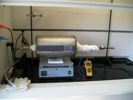
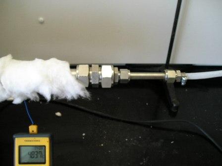
...After being subjected to activation (i.e., in an SO[2]/O[2]/N[2] atmosphere at 480 °C), the catalysts take up SO[3] and thereby crystalline sulfate is converted to molten pyrosulfate; the molten phase of the catalysts is shown to consist of (V[V]O)[2]0(SO[4])[4]4- (dimeric or binuclear fragments of oligomers) and V[V]O[2](SO[4])[2]3-. Below a certain temperature, which strongly depends on catalyst composition, the Raman data are indicative of V[V] → V[IV] reduction and formation of the molten V[IV]O(SO[4])[2]2-complex, the accumulation of which results in precipitation of V[IV] crystalline compounds-mainly K[4](VO)[3](SO[4])[5]-and depletion of the active phase in terms of vanadium. In reducing conditions (i.e., in SO[2]/N[2] atmosphere) the V[V] → V[IV] reduction and V[IV] precipitation occur at higher temperature. The low-temperature (i.e., below 420 °C) catalytic activity is related to the stability of vanadium in the +5 state...


http://cat.inist.fr/?aModele=afficheN&cpsidt=14768828

I've also read a thesis on this, but haven't been able to find it online.

Rosco Bodine - 11-8-2007 at 09:51

IIRC the activity of the catalyst in terms of reaction speed increases with temperature , but the equilibrium for completion of the oxidation of the SO2 also shifts backwards towards the incomplete oxidation ....sooooo
this would favor a long tube design where the inlet mixture is solidly preheated to the ignition temperature ,
and enters the catalyst also preheated to that ~450C ,
and then climbs to its peak reaction temperature in the
middle region of the catalyst , and finishes in a reaction
zone of gradually decreasing temperature towards near
or even below the inlet temperature . When operation commences , the supplemental heating should be cut way back on everything except the preheating "ignition" section , if efficient operation and an adequate flow of reactants is providing sufficient exotherm ....otherwise
catalyst in the molten state is likely to be what will be in use soon enough . As for me , I wouldn't go there unless the contraption is designed something along the lines of a
bessemer converter :D which can gargle fumes of SO2 to SO3 through a molten froth of V2O5 and its various pyrosulfate mp modifiers , as this would be quite a cup of hot soup at the vilest boil :D

As for following the progress of the increase in the SO3 content of the oleum .....a scale supporting the receiver
would be the easiest monitoring and simply follow the weight gain . A three way stopcock could be used to
divert output to a second receiver when the first is finished , so that the flow doesn't need to be interrupted .

not_important - 11-8-2007 at 19:22

Quote:
Originally posted by Rosco Bodine
....otherwise
catalyst in the molten state is likely to be what will be in use soon enough . As for me , I wouldn't go there unless the contraption is designed something along the lines of a
bessemer converter :D which can gargle fumes of SO2 to SO3 through a molten froth of V2O5 and its various pyrosulfate mp modifiers , as this would be quite a cup of hot soup at the vilest boil :D


However it is in the molten state in modern converters, as a film on the support material - not as a pool of liquid. I've read several books on industrial catalysts, and you can follow the progress in time from "add these other salts and it works better for some reason" to "adding these salts results in a layer of molten catalyst" to that I posted above, where the formation of a sold phase results in the lowering of catalytic activity.

This is one reason that molecular sieves may turn out to be less satisfactory than some other supports; M.S. for drying are usually 3A or 4A, their pore size is much too small for the interior region to accessible to the catalyst. The support needs good meso- and micro- scale porosity, but the nano-scale pores are generally too small.

Rosco Bodine - 11-8-2007 at 21:05

You could try rolled cylinders or crumpled wads of stainless or monel filter cloth for your support or even stainless steel wool . The kaowool could be a problem . The pelleted composition of US4285927 using DE makes more sense than kaowool ... IIRC kaowool is attacked by alkali . The DE actually would be attacked also , but DE is principally SiO2 with a lot of feathery thin structured edges like snowflake crystals which would sinter under high temperature with alkali , forming a glass bonded porous quartz structure having the V2O5 and K sulfate entrapped in the crevices .

[Edited on 12-8-2007 by Rosco Bodine]

not_important - 12-8-2007 at 07:49

The conditions are acidic, NH4VO3 being the most alkaline compound and that's just until the convertion to V2O5. The alkali metal sulfates are converted to acid sulfates and pyrosulfates under reaction conditions. Is stainless steel able to stand up to pyrosulfate + SO3 at 500 C?

Eclectic - 12-8-2007 at 08:06

I recommended mol sieves, activated alumina, and silica gel, just as a possible source of wettable inert beaded ceramic carrier. I don't expect that any useful reaction will occur other than at the surface of the bead. The idea is to have flow channels through the catalyst bed without danger of compaction and flow blockage.

Rosco Bodine - 12-8-2007 at 08:49

The conditions are alkaline during the initial formation of the catalyst , and before it is exposed to SO2 .

I think stainless will probably hold up okay .
If stainless doesn't withstand the atmosphere , then you will have to coat it with something or else use quartz .

Silica gel kitty litter would be about the right mesh .

Fleaker - 12-8-2007 at 10:06

Quote:
Originally posted by not_important
The conditions are acidic, NH4VO3 being the most alkaline compound and that's just until the convertion to V2O5. The alkali metal sulfates are converted to acid sulfates and pyrosulfates under reaction conditions. Is stainless steel able to stand up to pyrosulfate + SO3 at 500 C?


I do not know why we're asking this question? Stainless is what is used in industry. I opened the tube that had been run ~650 C and there was superficial oxidation, not severe corrosion. It is really quite the same as the outside of the tube that was exposed to oxygen at 650 C.

Kaowool is easily fluxed by a variety of things--borax will eat a hole through it like water through cotton candy. Alkali oxides and hydroxides attack it, but I doubt that K2SO4 (at these relatively low temperatures) will be an issue.
Kaowool is a high temperature and relatively inert material--it's just finely divided aluminosilicate strands. 650 Celsius is not much for the Kaowool I'm using, as its working temperature is 1200 Celsius.

I've used stainless 200 mesh ''cloth'' before to hold catalyst, and from experience I can tell you that it is NOT as effective as you would think. Per unit of area, there is a small amount of catalyst and to get it to properly adhere to the substrate, a thickening agent must be used (i.e. PVA).

Rosco Bodine - 12-8-2007 at 11:36

I wonder if you couldn't take a 14 gauge coil heating element and slip inside it a close fitting ceramic or quartz rod , maybe oxidative cold soak a vanadium oxide adhesion layer , or perhaps precipitate on the coil a silica gel bonding coating , and then dip the coil in a slurry of the DE plus KOH and V2O5 mixture . Energize the coil
to lightly bake the coating , and maybe slide it through a short section of throated flared tube of the same size as will hold the coil , as a sizing die to get the finish diameter
right on the coated coil . The idea is that inside the housing , the SO2 and air mixture will have to travel a
long spiraling path , as in a Friedrichs condenser ...which will increase the contact of the mixture with the catalyst .
It might multiply the length of travel to something like two
hundred times over what would be gotten in a straight tube . If a quartz housing was used , the thing could be energized like a ketene lamp and maybe would be called an SO3 lamp :D

Fleaker - 12-8-2007 at 16:15

Unfortunately, I don't have an unlimited budget. I spend too much on labware and chemicals as it is :-\.

Still, an interesting idea but doing all this is already expensive.

Further Success

Fleaker - 17-8-2007 at 16:43

Well now that my hands are dry and my face is stinging, I'm proud to report that the new catalyst I made some days ago worked a treat. Also managed to burn up some more tubing, this time it was PFA and tygon though :-\. There was much more SO3 produced this time, at much faster flow rates, and using the pyr.SO2 test, there was no SO2 escaping. As a matter of fact, I had some issues with the teflon tube clogging with sulfur trioxide--it took a while until the tube heated enough for it to melt/sublimate away. I am 100% certain now of SO3 formation, and quite a bit of it.


I'll now start my report with the aftermath of the first run:


This is Silex silicone tubing--the SO3 charred and ate a hole through it, it had zero flexibility after the reaction. The inside was filled with a sand-like material.


You can see how opaque it is. The ends were not affected because they did not contact the SO3.


After disassembling my old reaction tube, this is what I extruded out of the tube.
Now for catalyst preparation. I used kaowool, alumina powder, and 4A molecular sieve on this with a good bit of V2O5 and a few grams of K2SO4. It was all again dissolved in concentrated ammonia water, this time producing quite a bit of heat. Then it was left to bake at about 140 Celsius for 5 days, then pyrolyzed at 220 for an hour, then at 330 for 6 hours.


What I used to make it and the product after the bake out at 140 Celsius.


A close up of the baked out product.


The V2O5 on alumina. When I pulled it out of the oven, it had a red skin on it, then upon cracking the skin, there was the yellow of ammonium vanadate.


A picture of the catalyst in a 2.54 cm/1" diameter quartz tube in the tube furnace. This is after the hours of pyrolysis and there was some colour change, most of the yellow went to orange-brick red. I separated the alumina from the sieve by using kaowool plugs. As a note, you may see various colours like greens and blues--that's the camera's mistake.


Next up are pictures of the updated setup. Switched to a meter foot long stainless tube of the same diameter as last time. I found about a meter of PFA (1/4" I.D. ) tubing thinking it would serve better...


That picture was taken from near 2m in height (I'm a tall guy) so it's a big setup. Almost too big for my hood.


So now for the reaction:


An overview (for the most part). Note that I didn't use the stainless coil--why? I was worried about lack of heat transfer and SO3 solidifying in the line, good thing I thought of that!


I wrapped the exposed 45 centimeters of tubing with kaowool. As you can see from the thermocouple, it did a good job keeping in the heat. Temperature ranged from 510 C at the right exit of the tube furnace to 350 at the middle to 60 at the connection of the PFA tube. The inside of the tube furnace was at 585 C. It was ~460 at the input/left side (I did not plug this with Kaowool to keep in the heat) of the apparatus.


Even though the flow is stopped, you can see that the PFA tubing is coated with some of the SO3.


The SO3 going into 350.0mL sulfuric acid via fritted bubbler and getting nice and toasty.


An empty test tube.


Same test tube, top is clear, but you can just see the fog at the bottom of the picture.


This is SO3 sitting at the bottom. Obviously it has reacted with moisture in the air, and would probably be better to call it H2SO4. Unfortunately for you all, in my excitement, I forgot to get a picture of a test tube that I had coated with SO3. It was perhaps a millimeter thick and I was able to scrape out a somewhat waxy material. This was surprising, I was expecting a liquid, as it was probably 20 Celsius in the laboratory, maybe a little less. In the PFA tube, it was a liquid but it was also a white wax type material as well?!


This sulfur trioxide takes no prisoners! Even PFA!


Tygon didn't have a chance. I used this stuff to make a better connection to the bubble vessel.


Although I ran this reaction at 585 C (at the centre thermocouple) the temperature made it up to 623 Celsius. I also ran at a decent flow rate.

The PFA tubing did rather well for about 10 minutes, then as the SO3 got hotter--that was when the problem started, the sulfur trioxide was charring the tube. SO3 really reacts with the skin--my hands are still dry.

I'm convinced now. I think this is a feasible way to make a lot of SO3. Now for the sulfur burner.


Fleaker


Next up is ketene.


[Edited on 17-8-2007 by Fleaker]

[Edited on 17-8-2007 by Fleaker]

12AX7 - 17-8-2007 at 18:31

You took pictures closer than your camera's macro focus! GAH!

Awesome work Fleaker :D

Fleaker - 17-8-2007 at 18:33

Thanks.

I'm no photography expert...perhaps I need to import Woelen to get the job done right :P

MargaretThatcher - 18-8-2007 at 17:15

Splendid.

einstein(not) - 20-6-2009 at 11:01

Can alumina or mullinite tubes be used for this method?

watson.fawkes - 20-6-2009 at 11:56

Quote: Originally posted by einstein(not)  
Can alumina or mullinite tubes be used for this method?
As I have read, but not yet personally tried, the answer is yes.

Fleaker - 21-6-2009 at 08:52

I like the ''yet'' part of your statement watson.fawkes! I had very encouraging results with this experiment and I have no doubts that you could probably make quite some improvements on it (you seem to be some sort of engineer).

watson.fawkes - 21-6-2009 at 09:10

Quote: Originally posted by Fleaker  
I like the ''yet'' part of your statement watson.fawkes! I had very encouraging results with this experiment and I have no doubts that you could probably make quite some improvements on it (you seem to be some sort of engineer).
See US Pat. 4810685, "Foam catalysts, method of manufacture and method of using" for a project I'm keen on working on.

einstein(not) - 21-6-2009 at 21:15

Any advice on how and what to couple to the end of a 1 inch mullinite tube? I have some gound glass 24/40 male and female ends that I'd like to use but not sure how to attach them. I was thinking perhaps some sort of compression coupling but brass is the only thing readily available. I'm sure I could find stainless steel soemwhere. What about silcone rubber or fire cement? This is my first time dealing with mullinite and I'd hate to damage a $40 tube.

watson.fawkes - 22-6-2009 at 06:24

Quote: Originally posted by einstein(not)  
Any advice on how and what to couple to the end of a 1 inch mullinite tube?
Unfortunately not any I have huge confidence in. It depends, from what I've read, quite a bit on what you're doing. The most important thing always seems to be the temperature at the seal, followed by chemical compatibility. I have seen a method of brazing (!) to mullite for vacuum tube work (!!); the conditions required to need such a material must be pretty extreme. There are various refractory luting compounds around, but these seem to have fallen out of favor since precision machining and superalloys became cheap. Luting is sealing with a paste at high temperatures; you see the phrase "well-luted vessel" all the time in old laboratory texts. There are compression fittings also. These are pretty standard, although you should use a high-temperature elastomer like Viton as the compression ring. Such fittings, though are plenty pricey, likely more per end than you'll pay for the tube itself.

Apropos of the topic this arose in, however, there's what to use when dealing with SO3 and the contact process. In this case, I'm guessing that cast sulfur would work. Think of the old method of joining cast iron waste pipe with cast lead and oakum. I have to think that essentially the same technique is applicable here. You can seal glass or metal with this technique. Significantly, there are no chemical compatibility issues. Temperature management, though, becomes paramount. Please watch, now, while I think aloud.

First and paramount is the need to keep the temperature maintained. There are two viable operating regimes: one solid and the other in its liquid-thermoplastic regime. The solid regime requires more cooling, but no particular control system. The thermoplastic regime requires less cooling but thermostatic control to keep it in the right state. For lab scale, I'll consider the situation where more cooling is easier than a thermostat.

For an SO3 reactor specifically, though, there's likely a need for external cooling because both oxidations, S --> SO2 and SO2 --> SO3, are exothermic and generates a lot of heat. The temperature range of catalyst operation is about 425 - 625 C, which range contains the boiling point of sulfur. Industrial contact plants use intermediate gas cooling between catalyst beds to keep the temperature low enough to avoid excessive thermal dissociation of SO3. The contact temperature is typically in the range 75 C - 105 C. The engineering issue is to manage the two sources of thermal gradient, one from the center of the tube to its ends and one from the inside of the tube to the outside. There's a certain amount of heat to reject, and you deal with it. Some physical facts: A 1" tube has about a 3 mm wall. The melting point of sulfur is 113 C. The thermal conductivity of mullite is 6 W / m / K at room temperature, dropping with increased temperature. I'll use this figure as a constant, providing a margin of error. The formula for heat dissipation is given by Fourier's law.

The gradient from middle to ends is easy. Just buy a longer tube. Mullite is a pretty good thermal insulator, and putting distance between a cold end and a hot middle is easy and cheap. A secondary technique is to put a reflective flange around the tube where it exits the central furnace. This acts as a radiant heat insulator. It should be shiny. To model the conductive heat flow, I'll take a 24" tube divided into thirds: cold/hot/cold. We have about 6" from hot to cold, then; I'll take it as 15 cm. The temperature difference is (625 - 75) K = 550 K. The cross sectional area is about 200 mm^2. The total heat load is 4.4 W, which is negligible. The actual temperature difference is probably higher, but won't be more than double.

The inside-to-outside gradient generates a need for active cooling. Treat it like a PC modder would, with a cooling coil brazed up from some copper refrigerant tubing, a coolant pump, and a radiator. Such systems are really quite good at rejecting heat. I'll compute an unrealistically high upper bound. I'll take the contact area as 20 cm (about 2.5 cm contact area). Take as a target a 75 C surface temperature. The temperature difference is (625 - 75) K = 550 K. This is the model of a furnace running full bore where there's so much SO3 that you're not trying to cool it but just keep the seal in place. The total heat load in this (overcapacity) example is 2200 W, or a very large space heater, and less than a typically car radiator is capable of. I consider this evidence of feasibility. In practice, you're just not making this much SO3 at bench scale. The real heat flow is governed by the flow rate of the SO3 and its heat capacity. You need to cool it down anyway, and you might as well cool down the end of the tube to do it. I'm guessing that 300 - 400 W or so of cooling would suffice at lab-scale flow rates (but I haven't yet done the computation).

For safety, I'd embed thermocouples into the sulfur seal material to ensure they didn't get too hot. This would be a failsafe against seal failure.

There will be some contact between hot gas and the sulfur seal. Some of the sulfur will melt. What you don't want is for the sulfur to run out. What I would do is to orient the tube vertically and use gravity to hold the bit molten material in place. Since SO2 isn't particularly corrosive, put the SO2 inlet on the bottom and fabricate a metal cup that goes into the bore. The SO3 outlet is on the top of the tube. As long as the bottom doesn't melt out, there's no need to do anything else at the top.

einstein(not) - 22-6-2009 at 13:11

Excellent idea! This is the reason I post here. I'm using a small lindburg furnace and this tube is about 12 inches longer than the box is wide so I'm think heat transfer my not be an issue. Won't be able to use it vertically though. Thanks again for the excellent insight.

12AX7 - 23-6-2009 at 03:06

Will the sulfur not be oxidized by the SO3?

Tim

watson.fawkes - 23-6-2009 at 05:16

Quote: Originally posted by 12AX7  
Will the sulfur not be oxidized by the SO3?
Probably. I am under the impression, and I very well may be mistaken, that this is pretty slow when the sulfur is cold. Honestly, I'm not sure even why I have this impression, and while I did do a fair amount of reading on sulfuric acid last year, it was by no means exhaustive.

Anybody?

Saber - 24-6-2009 at 10:26

This is rather off topic however I thought it was important enough to mention.
I know I don’t have any picture to prove hover come the 2nd August I will post a thead in pre-publication on my contact plant.
Interested in research into various catalysts into the oxidation of SO2 --> SO3, I went out and bought 5g of ‘Platinised Kaowool’ This stuff cost £39.99 however you get surprisingly a lot and I thought it would be a great catalyst for a variety of other projects.
I took out the V2O5 cat. Tube from my mini plant and replaced it with 0.8 gram (again this is quite a lot, it just sounds little ) of platinised kaowool.
The result was far more efficient than my V2O5 cat. The Pyridine test showed very very little SO2 present at all! And the 0.8g of catalyst covered only 5cm of 14mm bore tubing.
Now how quickly does a Pt. Catalyst spoil and is there any way of re-activating the spent catalyst?
Will post pics asap!


[Edited on 24-6-2009 by Saber]

Contrabasso - 24-6-2009 at 11:12

Some asides!
Great work for making it possible.

I'd been thinking of fabricating a glassware venturi aspirator pump, and a glass magnetically coupled pump. Now I think could one use a mag pump to drive an aspirator pump, could one use an aspirator pump to draw the gasses through a sulphur burner and a V2O5 tube.

This would mean that the process ran at a slightly reduced pressure drawing in SO2 and air and in the final stage water was recycled through the aspirator and pump with surplus gas passing via the sump pot and scrubbers to atmosphere.

You would start with dissolving SO3 into water to make sulphuric acid then dissolving further SO3 to make oleum. All done in glass pumped with a spinning magnet well sealed into a glass tube driven by a mag stirrer.

Saber - 24-6-2009 at 12:49

Dont try dissolve SO3 directly into water! it just leaves you with fumes of extremly corrosive H2SO4.
Instead Dissolve it into H2SO4 to form H2S2O7 then dilute this to reform more H2SO4.

Evanescent - 11-6-2011 at 14:13

I built a double chamber sulfur burner similar to what is described in the following patent chain.

... 4039289, 4526771, 4966757

It is a bit smaller and simpler than described in the patents but seems to work fairly well. I'm not sure exactly what the SO2 concentration is using this method, but you can make a lot of it when you turn up the feed air volume (tested up to 100 SCFH). I constructed it as follows:

1) Start with a 2" diameter, 10" long steel pipe.
2) Weld a 1/4" thick metal disk inside of the pipe about 2.5" in from one end.
3) Drill a 3/8" hole in the disk with a drill press.
4) Drill/Tap two 1/8" NPT holes in the side of the pipe about 1" to each side of the disk welded inside of it. This provides the two compartments with separate feed air.
5) Put an end cap on the end of the pipe with the larger compartment.
6) Drill/Tap the other end cap with 1/8" male NPT and 1/2" standard thread for a plug, and put this end cap on the other end of the pipe (the end closest to the metal disk). This is the top end of the assembly.
7) Wrap the bottom 5" of the pipe with high temperature silica cloth for electrical insulation.
8) Wrap 2 twisted strands of 30AWG nichrome wire around the silica cloth with 0.25" spacing. This ends up being about 13 feet of wire, which will deliver about 300W of power when connected to 120VAC.
9) Thread in all three 1/8" NPT to tube compression fittings. The two on the side are for the two feed air lines and the one on the top end is for SO2.
10) Place a thermocouple near the heating element and insulate the whole assembly. I used kaowool.

Hook the the heater element and thermocouple to a temperature controller and the feed air lines to air flow regulators. When filling, I set the temperature controller to about 300C and heat the whole assembly. I then melt about 1 lb of sulfur an pour it through the 1/2" threaded plug hole and it flows down into the bottom chamber. There are much better ways of setting this up, but did not want to deal with the complexity of a hopper and continuous feed line for the sulfur now.

I put a plug in the 1/2" plug hole and set the temperature to about 410C (just below boiling point). After heating up, I push air through both feed lines at about equal rates. The air entering the sulfur chamber burns some sulfur, and the gases pass into the next smaller chamber and are combined with more air to finish the burn and provide surplus oxygen. This seems to work fairly well, and is capable of producing lots of SO2. You just have to get the feed rates right... if you don't provide enough air in the second burn chamber, not all of the sulfur vaporized in the first one will burn and this will fowl/plug the exit tube and the SO3 reactor. You also won't have enough spare oxygen to produce the SO3.

Also, use stainless steel fittings and tube. Copper tube reacts with sulfur and will not last long.


[Edited on 12-6-2011 by Evanescent]

Magpie - 11-6-2011 at 14:31

Nice work. I had always assumed an atomizer of some type would be necessary for an efficient sulfur burner.

Evanescent - 11-6-2011 at 16:21

Yeah, while researching I saw several examples of sulfur burner products that used an atomizer, but these were for very large industrial SO2 producers (many kG per hour)... not really necessary for lab scale production. Sulfur ignition point is somewhere around 230 to 260C (depending on the source), so heat it up and introduce oxygen and it will burn.

Evanescent - 12-6-2011 at 08:09

Fleaker, you have been doing a great job with the SO3 reaction, so I have duplicated some of your work and am trying to produce methods for SO2 production (see above) and the absorption of SO3 in H2SO4. I've been following your work for a while, so decided to join in and share what I have been doing...

A single H2SO4 bubbler is not very efficient, an absorption tower with bubble caps would be better. However, this is a bit large and expensive for lab scale production. I have a small 0.5" diameter column that I packed with glass beads. I installed this vertically on a reservoir holding H2SO4, and used a peristaltic pump with Viton tubing to pump the H2SO4 to the top of the column where it would bubble through the packing material with the SO3/air mixture passing vertically through it. The 0.5" diameter was much too small for the flow rates. I could not go much over 10 SCFH gas before I had issues. At 20 SCFH, the H2SO4 would bubble and splatter out the top of the column because of the high vertical flow rate of gas and the heat of reaction causing splattering. I would like to have a much larger diameter column with more open space for passage of gas. I have been thinking of using a Vigreux column (instead of packing) with a diameter of 1" or more. Some cooling would also help...

Magpie - 12-6-2011 at 08:42

That's interesting work, and it's nice to see someone taking this approach. I presume you are trying to make oleum.

One word of caution, when you get some oleum, how strong I don't know, I doubt if any plastic or polymer like Viton is going to hold up, except possibly perfluoros like ptfe, Kalrez, etc. I accidently threw a large drop of strong oleum onto the epoxy coating of my hood wall. It turned it brown. Even when I wiped this off it has left a permanent stain. Glass is good, and stainless steel is OK, for short term at least.

Also, any oleum, even 15%, is going to fume profusely when exposed to ambient air. This is a valuable visual indicator of its presence in the vapor state. Adequate ventilation is mandatory.

Evanescent - 12-6-2011 at 09:37

Actually, I looked this up before using Viton fluoroelastomer. According to Dupont's chemical resistance guide, it has an "A" rating for 20% oleum. I attached a screen shot below. Cole-Parmer says the same. I have not had any problems with it yet, and hopefully won't since the number of elastomers with oleum compatibility is almost non-existent. It is nice to use these with peristaltic pumps.


[On second thought, I removed the screen shot from DuPont's chemical resistance guide. I don't want to draw any unwanted attention to the forum... just take my word for it or look for yourself.]

[Edited on 12-6-2011 by Evanescent]


[Edited on 12-6-2011 by Evanescent]

Fleaker - 12-6-2011 at 19:01

Hey all!

I'm glad to see someone finally going for it! Any questions, ask! I made a few modifications that I never posted about. In my other thread on this, you can see that it pretty nastily charred FEP tubing that I had connected to the stainless via compression fittings.


I can say with some certainty that you cannot use FEP/PFA/Viton/Kalrez whatsoever if the SO3 is hot. At room temperature to about 180*C, FEP, PFA, and PTFE all tolerate it well. PVDF not so much at these high temps. Kalrez is better than Viton, but it won't take it forever, especially if it's hot.

Are you making oleum successfully?


I'll be back at it soon. I have some Cs (and Rb) to show you guys :-)
I'd also like to re-visit the ketene plant proper. I now have a much, much, much bigger tube furnace with a 2 m long quartz tube to use.

Magpie - 12-6-2011 at 21:09

Quote: Originally posted by Evanescent  


I have a small 0.5" diameter column that I packed with glass beads. I installed this vertically on a reservoir holding H2SO4, and used a peristaltic pump with Viton tubing to pump the H2SO4 to the top of the column where it would bubble through the packing material with the SO3/air mixture passing vertically through it. The 0.5" diameter was much too small for the flow rates. I could not go much over 10 SCFH gas before I had issues. At 20 SCFH, the H2SO4 would bubble and splatter out the top of the column because of the high vertical flow rate of gas and the heat of reaction causing splattering. I would like to have a much larger diameter column with more open space for passage of gas. I have been thinking of using a Vigreux column (instead of packing) with a diameter of 1" or more. Some cooling would also help...


This is called "flooding" the column. I agree that a 0.5" column diameter seems a bit small. But you might try a more open packing like tiny stoneware saddles, broken glass, or even a stainless steel scrub pad loosely packed. If it still floods you will have to cut the gas flow rate, or as you say, get a larger column diameter.

It seems that applying some ice-water cooling to the column would help alot also.

In my 1956 version of Shreve's Chemical Process Industries it only mentions making 20% oleum using an absorbtion column. Do you have information suggesting higher % oleum is being made this way?


Evanescent - 13-6-2011 at 20:02

There have been two things keeping me from being successful at making oleum yet:

-My air supply is much too wet (as you discovered in your experimentation, Fleaker). A lot of my SO3 appears to react with the water vapor from the air feed and turn into H2SO4 mist. Right after the SO3 reactor, I pass the stainless steel exit tube for a little ways through warm water to reduce the temperature before it goes into the column. Quite a bit of sulfuric acid condenses in the tube because of the cooling water, and will actually start to gurgle after running for a little while. I put a flask at the end of the beaker and turned the gas flow up enough to push the liquid out (thinking it might be liquid SO3), and all I got was H2SO4 contaminated with metal compounds it stripped from inside the stainless steel tube. I got some molecular sieve and built a drying chamber I am going to attach in line with my air source before my flow regulators. Just a 1.25" diameter PVC pipe with a screen at the bottom and hose barbs at each end that stands vertical.

-The column diameter was too small and/or the packing material too dense. I had to run at very low flow rates to keep from flooding the column (as Magpie pointed out). There appeared to be a rather energetic reaction in the tube (more than just the bubbling of gas), as it appeared that the liquid was boiling/spattering in some places. It was going to take a long time to accomplish anything with the low flow rate I was running at and the exit tube from the SO3 reactor was gurgling again with H2SO4, so I just shut it down until I could improve the setup.

I have an air dryer now, so can insert that into the system. I also ordered a 1" diameter column I am going to try out. I would prefer to have an even larger diameter, but this is the largest one I could find without building something custom and spending lots of money. This hobby seems to greatly reduce my spare funds...

You can use a packed column as an absorption column... your goal is just to have a lot of liquid-to-gas surface area to enhance absorption. The same types of column construction used for distilling can be used for absorption. I may still have issues with flooding, but should be much better than before. I'll try some other packing materials as well if I still have problems.

My biggest success so far was in getting the sulfur burner to work reliably. I've heated it up and run it a few times already and have not had any issues with it. Once it gets hot enough for the sulfur to ignite, it produces more than enough SO2 for my experimentation.

Magpie - 13-6-2011 at 20:28

It looks like you are making steady progress. I think you have set quite an ambitious goal: going from elemental sulfur to oleum in one continuous train. Getting everything tuned to run in harmony will be quite an achievement. This also, as you say, takes some funds. I find that once you get beyond the textbook experiments it seems like you always need some new, expensive equipment.

Gammaray1981 - 3-12-2011 at 20:25

Just to make sure I understand what's gone before, I just sketched this:


The bubbler/absorption tower on the right should be about 2-3" across, I think, to ensure that evolved heat can't cause unpleasant consequences. The tap above it for H2SO4 replenishment ought probably be left open, or else it looks like a sealed system.

The cooling coil is within a 'bucket' of water, which might as well start out from the hot tap, about 40 Celsius. This should have a cone full of ice or similar above it so that the water doesn't all evaporate.

Air is added to the combustion chamber to make sure there is sufficient oxygen around. CO2 and moisture are removed in hopes of avoiding having too many other things going on - as is stated in the top-left note box, an oxygen generator would be far better.

What do you think of smashed pumice as the substrate? Glassy, porous, light, and as far as I know it shouldn't mind 600 Celsius.

Have I missed anything?

[Edited on 4-12-2011 by Gammaray1981]

Magpie - 3-12-2011 at 20:55

Quote: Originally posted by Gammaray1981  

Have I missed anything?


How does N2 leave the system? If you simply leave the absorbtion tower vent open you will lose the recycle SO2 and O2, as well as bleeding off the N2.

Gammaray1981 - 3-12-2011 at 21:05

Hm. The O2 isn't really an issue, if the N2 is - it's just coming from the air. I suppose the recycle line could be run through a dry-ice/acetone bath and the O2 and N2 vented afterwards. The then-liquid SO2 would have to be allowed to return to gaseous form before it was recycled, though.

That's an additional layer of complication, of course, but the alternative is venting SO2 to atmosphere - or attempting to convert it all in one pass, which by the looks of this thread and the relevant patents isn't possible, or would take a much longer tube furnace.

Magpie - 4-12-2011 at 09:17

I checked a flow diagram for the contact process in Shreve's "Chemical Process Industries." It shows the vent at the top of the absorbtion tower. So industry is just venting the N2 and any other unreacted/absorbed gases, at least back in the '50s.

You might want to check Shreve and/or the process descriptions in Ullman's or Kirk-Othmer. The key phrase is "Contact Process for Sulfuric Acid."

Gammaray1981 - 4-12-2011 at 10:48

I don't have Shreve, though I suppose I could go to the Library, but I do have Kirk-Othmer handy. It states there that two-stage converters were initially used, with a conversion rate of about 95% SO2-SO3. Given the rate of increasing efficiency from thereon, I would put the one-stage efficiency at about 87%, so perhaps 80-85% for a home-built tube furnace and catalyst setup. Given the source is burning sulphur, that's an acceptable loss economically, but there remains the serious question of polluting the air and annoying the neighbours.

It is suggested that ammonia is used to scrub SO2 from the exhaust gasses, which would negate that problem.

Given these problems, I'm in favour of buying a used oxygen generator for this sort of purpose - it's not like a torch, where huge flow rate is important, and the output is dry. Efficiency savings all round, I think.

watson.fawkes - 6-12-2011 at 21:01

Quote: Originally posted by Gammaray1981  
It states there that two-stage converters were initially used, with a conversion rate of about 95% SO2-SO3. [...] Given the source is burning sulphur, that's an acceptable loss economically, but there remains the serious question of polluting the air and annoying the neighbours.
[...]
Given these problems, I'm in favour of buying a used oxygen generator for this sort of purpose
Commercially, the typical way of scrubbing the exhaust gasses from a contact process plant is to build a second contact process plant. The exhaust gas from the first is used as the feed gas for the second. Conversion efficiency is a nominal 95%. After two stages, you're down at 0.25% of feed sulfur left in the final exhaust gas, small enough for a regular scrubber.

Rejection of non-reacting gasses is the main emissions problem in any small scale contact process plant. I've convinced myself that tank oxygen is the right way to deal with the problem for a first prototype, essentially eliminating the problem except at shutdown. Make O2 the limiting reagent and you can get a gas-sealed system that doesn't build up non-reacting gasses. There are enough problems to work out for such a plant that it's prudent to eliminate emissions issues on the first round of development entirely.

The problem with an oxygen concentrator is that the Ar goes over with the O2, so that you have an approximately 95% O2 + 5% Ar mixture. That 5% Ar will still need venting, yielding all the SO2 emissions problems that you have just burning in air, except they take longer to show up.

White Yeti - 24-1-2013 at 08:18

Thread bump!

How about using sodium metabisulfite to generate SO2 for this reaction? The source of SO2 is really a matter of convenience. The partial pressure of water is negligible at room temperature, but a drying tube can still be used for comfort of mind if the atmosphere is humid.

violet sin - 24-1-2013 at 23:15

I just bought some V2O5 the other day and have been doing some research along the lines of SO2 production etc.. It sounded like a viable route to me but I was wondering how it would play out? I haven't heated the stuff to decomp yet.(no fume hood or ground glass) so I was wondering if it would all try to come out nice and steady or whoosh? you may have to use your air supply to blow it through to the cat, or matching air/O2 flow rate mixer just prior depending on SO2 production rates. proper cooling could be difficult also.
also if it decomps like wiki says the similar K version does, K2S2O5(s) → K2O(s) + 2SO2(g), you would be left with Na2O. lye for your trouble is a decent bonus.

hissingnoise - 25-1-2013 at 03:21

Quote:
I just bought some V2O5 the other day and have been doing some research along the lines of SO2 production etc.. It sounded like a viable route to me but I was wondering how it would play out? I haven't heated the stuff to decomp yet.(no fume hood or ground glass) so I was wondering if it would all try to come out nice and steady or whoosh? you may have to use your air supply to blow it through to the cat, or matching air/O2 flow rate mixer just prior depending on SO2 production rates. proper cooling could be difficult also.
also if it decomps like wiki says the similar K version does, K2S2O5(s) → K2O(s) + 2SO2(g), you would be left with Na2O. lye for your trouble is a decent bonus.

Your post doesn't seem to make much sense ─ is it me, or are you talking through your hat?
V2O5 is reduced, reversibly, to VO2 on heating!
And where does lye, the old name for NaOH, come in?


hissingnoise - 25-1-2013 at 04:00

OK, lets try again, your wording is ambiguous and very confusing, but SO2 from bisulphate decomp. is oxidised by V2O5 @ ~500°C and the produced VO2 is oxidised in air, regenerating the catalyst . . .


violet sin - 25-1-2013 at 04:41

ya sure is. what I was saying was I was researching certain aspects of the reaction. I have much to buy for this to build a proof of concept. one of the main issues is the need for high quality SO2. if you use a sulfur candle with air you have to scrub the gas of ash, H2O, etc. so to get better SO2 that doesn't need scrubbing you can go with a sulfur burner that is fed with only O2 or you can make it with a chemical rxn. one way of doing that is to use the Na/K metabisulfite heating it to decomp. hence the previous wiki equation. this leaves Na2O and makes SO2 only(supposedly). so you get your gas that shouldn't need to be scrubbed and when you wash out your glass (carefully) H2O + Na2O --> 2NaOH,,, free lye. seeing as how I don't have a fume hood and ground glass I havn't been able to try the decomp and see how it proceeds. which is important, as you feed in the SO2 and O2 to the cat, it should be in proper proportions. too little O2 and it may not sustain temp for the catalyst. wasting materials and time. but the reaction is exothermic and if it came over too fast you have mix issues and/or it could overheat your catalyst. push too much heat would make the cooling inefficient. with out time for the mix to cool down the repeated passes through the cat bed are wasted. so you are wasting resources for nothing again. gotta balance incoming reagents to manage heat to effect cooling to maintain any sense of effiency. if your gonna build it from the ground up and deal with all the nasty chems you might as well do it good no? other wise it is just a big waste of time.

*forgot, reading suggested complexing the V2O5 with ammonia to make an ammonium metavanadate solution. this is mixed with a few % of K2SO4 and doused on the catalyst support. it's then heated to drive off the ammonia and there you have your evenly distributed catalyst. I hope to go with 0.5~0.75 inch ceramic bead grow medium from the gardenshop in a stainless tube(s) there is a LOT of info on this site about this subject and I have read quite a lot. no need to go down a bunch of dead ends when you can learn from others.


[Edited on 25-1-2013 by violet sin]

hissingnoise - 25-1-2013 at 04:55

It's so much easier buying your H2SO4, unless, of course. you want oleum . . .


violet sin - 25-1-2013 at 05:08

ya it absolutely is cheaper all the way around to buy H2SO4. but I like a challenge, and I am not saying I will succeed but I am sure gonna give it a try. when ever I can cobble something together in my spare time i'll work on it. also would it not kick ass to be able to say you build a small acid plant?! make a couple gallons once a year would be fine by me.

hissingnoise - 25-1-2013 at 06:11

Quote:
. . . but I like a challenge . . .

Well, it certainly is challenging ─ if you do produce SO3 you'll need conc. H2SO4 as absorbent because the trioxide will not dissolve in water, producing instead, a practically incondensible corrosively acid mist!


Adas - 25-1-2013 at 07:45

Quote: Originally posted by hissingnoise  
Quote:
. . . but I like a challenge . . .

Well, it certainly is challenging ─ if you do produce SO3 you'll need conc. H2SO4 as absorbent because the trioxide will not dissolve in water, producing instead, a practically incondensible corrosively acid mist!


Or instead, condense the SO3 and put a little piece of ice. This reaction would not be so exothermic. You can then dilute it with more ice.

Btw, if this is true, how did they make the first H2SO4? :D

White Yeti - 25-1-2013 at 08:18

Making sulfuric acid by this method is rather insensible, however, if you're after SO3/oleum, this is definitely worth a shot if you're willing to risk life and lung to do it.

If you want to make sulfuric acid just for a challenge, there are other, more challenging, yet safer things to try. I would argue that making hydrazine is much safer than pulling this off. If you read the prepublications section, you'll see that SO3 can manage to pass through a cooled u-tube, and a condenser all the way to a polyethylene tube and react with it.
http://www.sciencemadness.org/talk/viewthread.php?tid=10332

The tube shows you how your fume hood would look like after this endeavour if you omitted it (provided that you use a fume hood) and it shows you what your lungs would look like of you didn't bother using a fume hood. Of course, you'd be dead after the first few whiffs.

I'm an asthmatic, the thought of SO2 already sends shivers down my spine, but as for SO3, that's where mad science ends and insanity begins.

hissingnoise - 25-1-2013 at 08:23

Quote:
Btw, if this is true, how did they make the first H2SO4? :D

Oh, come on?

And before fucking around with SO3 it's well to read up on this compound's forms and its odd little dangerous trick . . .


Adas - 25-1-2013 at 08:36

Quote: Originally posted by hissingnoise  
Quote:
Btw, if this is true, how did they make the first H2SO4? :D

Oh, come on?

And before fucking around with SO3 it's well to read up on this compound's forms and its odd little dangerous trick . . .


Yeah, I know about "alpha explosion" - if that's what you meant :)

hissingnoise - 25-1-2013 at 08:46

I had to check, just in case . . .


Adas - 25-1-2013 at 09:57

Quote: Originally posted by hissingnoise  
I had to check, just in case . . .


I have got just the basic equipment so there is no way of making SO3 for me.

hissingnoise - 25-1-2013 at 11:02

. . . same boat . . .


violet sin - 25-1-2013 at 16:10

my envisioned version would be mainly durable s.s tubing, a tube furnace w/ *at least* 2 heat zones for multiple passes. the idea being more of a bundle of smaller tubes in one tube furnace with a gradient ~450-650'C. the length and position of the tubes in the parallel stack would define the zones for the repeated passes. that way if I got it right on one pass, I could start stacking more tubes for multiple passes for increased efficiency, providing the cooling could keep up of course. I don't wanna visit the alpha explosion either, even in an all metal construction it would be disastrous to say the least.

huge considerations are SO3 reacting w/ cooling media if it eats through = boom. alpha explosion or blockage from over effective cooling = boom. poor s.s heat conduction for cooling, SO2 leaks, vanadium toxicity, hot or even boiling H2SO4, oleum, storage of product, cost of machine, etc, etc, etc. the list of hurdles is HUGE to say the least. and that is just to get it working. clean up after a run would be the bitch as far as I can see.

but with a well thought out plan with room for flexibility, it could be possible to not kill your self and produce. hand making a large portion of the machine would be fun and rewarding. shouldn't be to hard to make a hand wound nichrome tube furnace in a 4 foot section of 8"terracotta chimney insert and kao wool insulation. wrap it with a healthy coating of carpenters cloth on the exterior to prevent fragmentation in the case of an explosion. only one small link in the chain though. maybe I will finish by next winter. maybe not. working away from home leaves much time to plan and little to act sadly. though there is much to be had/salvaged for free or cheap if you know where to look.

I would do this out side of course, no freaking in home fume hood considerations what so ever... laugh if you will, it does sound insane I know.

macckone - 2-9-2015 at 10:29

How was Sulfuric acid first made.

By creating sulfur trioxide from ferrous sulfate and dissolving it in
water in VERY small quantities. If the amount of water is large
enough and the amount of gas small enough you get very dilute
sulfuric acid. This can then be concentrated. Then the
concentrated acid can be used to gather larger quantities of
trioxide.

The second method was the chamber process which doesn't
generate the aerosol in the same manner so it condenses eaiser.

A number of people have good success distilling sulfuric acid.
This also results in a sulfuric acid gas. The aerosol should
actually be somewhat easier to deal with but you need a packed
column for the aerosol to accumulate on.

The bigger problem is the large amount of gas in the
intermediate step with the trioxide. You can't do this in a
sealed system efficiently unless the trioxide is combined
with steam and even then you have a significant expansion
factor. BTW, the lead chamber process usually used steam
input to combine with the dioxide as well as regulate the temp.

One catalyst substrate that is ideal that hasn't been mentionend
is perlite. It has a very large surface area. It contains several
percent of sodium and potassium. And the melting point is
sufficiently above the reaction temperature to not be a problem.

The primary concerns would be contaminants that could poison
the vanadium catalyst and absorption of water which could be
difficult to drive off before use.