Foeskes
Hazard to Others

Posts: 156
Registered: 25-2-2017
Member Is Offline
Mood: No Mood
|
|
Winding flyback secondary?
So I currently have 4 flyback transformers(1 usd for 3 transformers). One of them isn't very good(no space for winding primary) and I wanted an ac
flyback so I decided to take it apart and got the core and make a new one.
I know this question might sound dumb but when winding the secondary do you wind it to one side and back(i.e. 50 turns to one side then insulate then
50 turns back to the begining) or do you just insulate them make a straight line from the other side back(i.e. 50 turns to the other side then back to
the begining).
Hopefully that isn't too confusing.
I'm not sure since the first example seems to make the magnetic fields cancel out.
|
|
|
aga
Forum Drunkard
Posts: 7030
Registered: 25-3-2014
Member Is Offline
|
|
AS far as i am aware, you just wind a coil all in the same direction.
|
|
|
Foeskes
Hazard to Others
Posts: 156
Registered: 25-2-2017
Member Is Offline
Mood: No Mood
|
|
So after winding 1 layer you just bring the wire back to the begining and wind it again?
|
|
|
WGTR
National Hazard
Posts: 971
Registered: 29-9-2013
Location: Online
Member Is Offline
Mood: Outline
|
|
It makes no difference at all except for copper density in the winding. In other words, you may be able to get more turns by not crossing the wire
back under the next layer, since you'd avoid the lump that would form under the next layer. The fields wouldn't cancel unless you wound one layer
clockwise, and then wound the next layer counterclockwise. This would be difficult to do accidentally. The main thing to consider is voltage
isolation from one end of the coil to the other, and in between layers. Enameled wire can only handle around 1k-3kV between turns/layers before it
breaks down. If you insulate well between layers you'll probably be fine.
|
|
|
aga
Forum Drunkard
Posts: 7030
Registered: 25-3-2014
Member Is Offline
|
|
Just keep on winding.
When you get the first layer done, just keep winding and you'll soon end up back at the start when layer 2 is done. Same as a tidy cotton bobbin.
It helps if you can use an electric screwdriver to spin the coil former.
Makes it faster/easier/neater.
If you also have a revolution counter, easier still if you need an exact number of turns.
The first coil i ever wound had 350 turns of 38 SWG.
It was for a metal detector design by F. G. Rayer, Babini Books.
Took forever to wind it and the circuit didn't work in the end.
|
|
|
Fulmen
International Hazard
Posts: 1693
Registered: 24-9-2005
Member Is Offline
Mood: Bored
|
|
Winding in one direction reduces the voltage difference between the layers (by a factor of two), in HV applications this can make a difference.
We're not banging rocks together here. We know how to put a man back together.
|
|
|
markx
National Hazard
Posts: 645
Registered: 7-8-2003
Location: Northern kingdom
Member Is Offline
Mood: Very Jolly
|
|
Oh the rabbit hole of practical transformer design really goes deep. There are quite a few tips, tricks and aspects about winding these things....a
practical art on its own that really deserves a deeper plunge. Especially if we dwell into the high frequency domain of ferrite core transformers for
voltage conversions.
For example the struggle to ensure maximum coupling between the primary and secondary of a transformer. In reality there is always a portion of the
windings inductance that is not coupled into the energy transfer network of the transformer and it acts as a loose parasitic inductance in the
switching circuit: leakage inductance be the term.
This portion of the inductance will generate voltage spikes that destroy switching transistors or interfere with resonance characteristics and just
can be a major pain to deal with.
I ran into the issue when trying to wind transformers for DC-DC voltage converters and learned the hard way that transformer design is of utmost
importance to be able to build a reliable converter.
Depending on core geometry there are different elaborate schemes using parallel primary windings that are divided amongst and between the layers of
the secondary windings to ensure better coupling and less leakage inductance.
E.g. below one can observe a toroidal push pull type ferrite core transformer that I built for conversion of 12V to 800V at about 40kHz switching
frequency. It has eight parallel sections of primary divided over the entire secondary to ensure minimal leakage inductance:
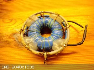 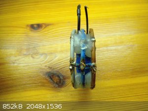 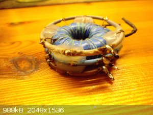
It is quite an elaborate design and I do not even want to mention about the actual pain of winding and building that thing by hand 
But that was a very successful example that I managed to devise after a series of failed designs. But not really something I would want to do again.
Exact science is a figment of imagination.......
|
|
|
Foeskes
Hazard to Others
Posts: 156
Registered: 25-2-2017
Member Is Offline
Mood: No Mood
|
|
I have 0.1 mm magnet wire on hand is that too small?
|
|
|
WGTR
National Hazard
Posts: 971
Registered: 29-9-2013
Location: Online
Member Is Offline
Mood: Outline
|
|
I don't have enough detail on what you want to do with the coil to give an opinion. I'm unfamiliar with an "AC flyback". Do you mean that you want
to make a high-voltage step up transformer that you drive with something like a Mazilli-type driver? Or do you want to wind a low power transformer
for a flyback converter for some low power ozone generation or something?
If you want to make one then I encourage you to try. The wire size may or may not be optimal, but you'll learn something. However, you can also get
the old style round automotive ignition coils from a salvage yard or even Walmart if you want around 50kV or so.
|
|
|
Vomaturge
Hazard to Others
Posts: 285
Registered: 21-1-2018
Member Is Offline
Mood: thermodynamic
|
|
From what I can tell, this wire should only have a resistance of two or three ohms per meter.
For a high voltage, low current (as in, fractions of an ampere, maybe a few amperes at most), high frequency (compact core, and only a few 10,000's of
turns at most) transformer, I think that would be fine. It might depend, a little, on exactly what you're using it for. A real fly back circuit* (the
ones that work similar to an old-fashioned induction coil, except with high frequency solid-state switching) would almost certainly work well with
.1mm wire, provided you didn't nick the insulation while winding. A ZVS/Mazzilli will probably be good with that wire, although I don't know how much
current and voltage those put out once an arc has struck.
@Markx, that's a serious coil! Especially considering how tedious it is to wind a toroidal core. It's an accomplishment to be admired, but not envied
How many turns is that? What current could it output? 12v-800v push-pull? That
wouldn't have happened to be the power supply to this railgun? Would it?
*Just a silly observation: there are four classes of devices sometimes called "flyback transformers."
1, The transformers from a TV, driven with a waveform (primary current ramps slowly, then is shut off fast) similar to that in a TV.
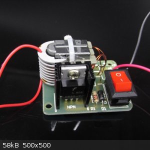
2. All kinds of transformers, driven by waveforms similar to the TV one. An example is this puny homemade blocking oscillator voltage converter, with
6 turns on the primary and feedback windings, and 120 on the output. The transistor is in the middle of the toroid, and it's "potted" in hot glue to
protect it, and make it ugly AF:  It operates on 1-3v, and makes 100ish volts as an output, enough for a tiny neon indicator bulb. It operates on 1-3v, and makes 100ish volts as an output, enough for a tiny neon indicator bulb.
3. TV flyback transformers driven with a ZVS, H-bridge, half bridge, push-pull, you name it.
4. Any kind of transformer, driven with any of the drivers in 3 (but not 50/60Hz mains), or in other words almost any high-frequency power converter
with a primary and secondary that was designed or built at home.
Just thought I'd share that. Better to reflect on it here, then to just say "a real flyback circuit" without explaining the "unreal" ones.
Edit: Flyback converters (with TV-like waveforms) are used in other appliances besides old TVs, but they got their name from their usage in television. When the primary current was abruptly blocked, the electron beam would "fly back" to one side
of the screen, and the secondary winding would emit its high-voltage pulse. But I somehow found the other explanation ("you'll fly back if you touch
it") amusing, in a dark sort of way.
[Edited on 4-6-2018 by Vomaturge]
|
|
|
markx
National Hazard
Posts: 645
Registered: 7-8-2003
Location: Northern kingdom
Member Is Offline
Mood: Very Jolly
|
|
Quote: Originally posted by Vomaturge  |
@Markx, that's a serious coil! Especially considering how tedious it is to wind a toroidal core. It's an accomplishment to be admired, but not envied
How many turns is that? What current could it output? 12v-800v push-pull? That
wouldn't have happened to be the power supply to this railgun? Would it?
[Edited on 4-6-2018 by Vomaturge] |
Effin' aye! That was a serious pain to assemble this monstrossity. Fortunately
there were not too many turns on the thing....if I remember correctly the secondary was about 160-200 turns or the like. With this kind of
transformers the direct ratios turns/voltage division do not tend to apply quite exactly any more. So it is a bit of a trial and error type of work to
get the correct output voltage. But really, winding the secondary was the easiest part on that build. Now getting the primaries divided equally and
all the sections soldered in the correct sequence....that was a challenge. Not a venture to be repeated in short !
It was not for a rail gun though....but in essence still a charging circuit for a high voltage DC cap bank that was used as a reservoir for an impulse
generator. Damn that still sounds suspiciously like a rail gun though
This little core (42mm) could transfer in excess of 400W of power without saturation when the switching circuitry was tuned into sweet spot. Quite
impressive, but of course the duty was quite humble at these power transfer rates or overheating of the core would become a problem. The IRF3205 based
switching circuitry became barely warm as the leakage inductance was low and no voltage spikes disturbed the clockwork.
Exact science is a figment of imagination.......
|
|
|
Foeskes
Hazard to Others
Posts: 156
Registered: 25-2-2017
Member Is Offline
Mood: No Mood
|
|
Any tips on insulating the layers?
I tested the old one I wound and it arced over, turns out 2 layers of klapton wasn't enough maybe wiping some epoxy on every layers.
|
|
|
Sulaiman 2
Unregistered
Posts: N/A
Registered: N/A
Member Is Offline
|
|
I recently bought one of these https://www.ebay.co.uk/itm/15KV-High-Voltage-Inverter-Genera...
There are also completely assembled/soldered kits)
The core is easily dis-assembled, different air gaps can be tried,
the primary is easily removed and re-wound ...
(a new tie-wrap required per modification)
(the spec. is 15kV but I dipped my secondary in polyurethane varnish by habit)
It could be used to ionise noble gasses etc.
It does light a cigarette.
A fun kit that runs off one lithium cell ... a moderately safe introduction to high voltages.
(by changing the resistor up to 12 Vdc can be used but I've not yet tried)
(short runs only, after about 10 seconds the heat sink gets too hot for my liking)
P.S.with just a 0.2" gap/arc I could smell ozone.
[Edited on 10-6-2018 by Sulaiman 2]
|
|
|
Foeskes
Hazard to Others
Posts: 156
Registered: 25-2-2017
Member Is Offline
Mood: No Mood
|
|
The main reason for winding my own is because I need an actual flyback and it's not available locally. Online it has a high shipping cost due to my
location.
I'm thinking about buying that kit mostly because it's easier to set up and takes less space than my current set up.
|
|
|
Twospoons
International Hazard
Posts: 1281
Registered: 26-7-2004
Location: Middle Earth
Member Is Offline
Mood: A trace of hope...
|
|
| Quote: Originally posted by Foeskes | Any tips on insulating the layers?
I tested the old one I wound and it arced over, turns out 2 layers of klapton wasn't enough maybe wiping some epoxy on every layers.
|
Yes, insulating HV windings can be a pain. If it doesn't arc through the insulation it will probably arc around it instead. Look up "tracking index".
Best fix is immersion in oil, or vacuum potting in epoxy or polyester resin.
I used to have a spectacular demonstration of surface arc tracking. It was an A4 size sheet of Mylar, which we would put between the output wires of
an electric fence energiser, modified to produce 25kV. Instead of punching through the Mylar the arc would travel right around the edge - total
distance of about 20cm! Thats why all our energiser transformers were vacuum potted in epoxy (we were in the business of building electric fencing
hardware).
Helicopter: "helico" -> spiral, "pter" -> with wings
|
|
|
Foeskes
Hazard to Others
Posts: 156
Registered: 25-2-2017
Member Is Offline
Mood: No Mood
|
|
I'm trying to insulate between the layers since I can't get the oil to completely fill the gaps.
My homemade vacuum pump is not very good. My idea is to fill the area between the wires with epoxy and use some insulating plastic before putting the
next layer.
|
|
|
MJ101
Hazard to Self
Posts: 82
Registered: 14-6-2018
Member Is Offline
Mood: Always Sunny
|
|
Hi Foeskes,
You might consider this for insulating the winding layers.
MG Chemicals 4226-1L Super Corona Dope.
https://www.mouser.com/Tools-Supplies/Chemicals/_/N-wp63?P=1...
With fine gauge wire like that, Corona Dope might be your best bet. For higher current windings, you'd use nomex tape and fish-paper between the
winding.
Are you using this flyback to power the 2nd anode of a CRT? I ask this because some flyback transformers have an integrated HV diode in the secondary.
Best of luck with the wind. The last one I did was a 15 inch Tesla coil secondary. My hands hurt for 2 days afterward.
|
|
|
A Fresh Lunatic
Harmless
Posts: 5
Registered: 24-10-2013
Member Is Offline
Mood: No Mood
|
|
You may all be interested in this small booklet from 1951, "Small AC Transformers" by A C Avery, ive scanned in and turned into a PDF. It was the
definitive pocket guide when I was a Radio Ham in my teens, back in the early 15th century........ The detail it goes into in terms of how to
calculate windings for transformers of all sorts is superb. Please feel free to download and copy.
https://app.box.com/file/303845307237
[Edited on 11-7-2018 by A Fresh Lunatic]
|
|
|
wg48
National Hazard
Posts: 821
Registered: 21-11-2015
Member Is Offline
Mood: No Mood
|
|
| Quote: Originally posted by A Fresh Lunatic | You may all be interested in this small booklet from 1951, "Small AC Transformers" by A C Avery, ive scanned in and turned into a PDF. It was the
definitive pocket guide when I was a Radio Ham in my teens, back in the early 15th century........ The detail it goes into in terms of how to
calculate windings for transformers of all sorts is superb. Please feel free to download and copy.
https://app.box.com/file/303845307237
[Edited on 11-7-2018 by A Fresh Lunatic] |
I wanted to down load it to take a look but I will not join box to do so.
Why not attach a copy to a post or is it just click bait?
Borosilicate glass:
Good temperature resistance and good thermal shock resistance but finite.
For normal, standard service typically 200-230°C, for short-term (minutes) service max 400°C
Maximum thermal shock resistance is 160°C
|
|
|
MJ101
Hazard to Self
Posts: 82
Registered: 14-6-2018
Member Is Offline
Mood: Always Sunny
|
|
@wg48: I hope it's not clickbait, because that book is only available in printed format.
|
|
|
RogueRose
International Hazard
Posts: 1585
Registered: 16-6-2014
Member Is Offline
|
|
Two questions. I have a HID light transformer/ballast (250 watt) that is about 15" x 3" x 2.75", the steel core inside is about 11-13" long and the
coils are on either side of the transformer with about 1.5-2" space between the two. There seem to be A LOT of windings for a 250 watt transformer as
it probably has 2-4x the copper that a microwave transformer has. I'm sure the ratio is the same for the voltage step up, but it seems that for every
turn the MOT has, the HID trans has 2-4 windings.
Also, since most people rewind the secondary of a MOT, could we not rewind the primary with a fairly high gauge wire? If it is putting out 2000V in
"stock" mode, and has 16-17g wire, then using something like 12-10g we might be able to get 10-20K, maybe up to 30-40K even and at a fairly high
amperage in comparison to TV flyback's. I would think that the insulation on the HV side might be an issue as it might blow out.
|
|
|
wg48
National Hazard
Posts: 821
Registered: 21-11-2015
Member Is Offline
Mood: No Mood
|
|
Roguerose:
First some brief relevant transformer theory.
The more copper in a transformer the thick the wire for a given number of turns. Thicker wire has lower resistance hence low resistive losses for a
given current flow.
The more iron in a transformer of conventional design the more flux for a given magnetisation current which results in a larger back emf per turn. A
larger back emf per turn means few turns. Fewer turns for a given amount of copper means thicker wire with a lower resistance hence lower resistive
losses.
Lower flux density in the core means lower core losses due to eddy currents and hysterisis losses. Meaning more iron can be operated at a lower flux
density for a given total flux.
Answer to Q1: I Guess what you are asking is why has the ballast transformer got 2 to 4 times as many turns as an MOT. In general MOTs are designed
for intermittent use and for fan cooling. That allows the designer to operate them with higher core and copper losses which results in few turn for a
given voltage. Overall it results in a cheaper MOT for a given power rating. The ballast would have been designed for continues use, without fan
cooling and therefore requires higher efficiency (less losses) meaning more iron and copper for a given power rating.
Answer to Q2: I guess what your asking is can you operate a MOT with few turns on the primary?. In general no, because that would increase the
voltage per turn which would require more flux to achieve the required back emf. As described above MOTs are design with high levels of flux near the
saturation flux level of the iron core. Increasing it would lead to saturation of the core and with limited back EMF to limit the magnetisation
current the current would increases very significantly. If the breaker did not interrupt the current the MOT would rapidly heat up and fail as the
insulation breaks down due to excessive temperature. Note in general the high voltage failure of the secondary is caused by flash over to the core.
Typical this occurs at about 5kVrms wrt the core.
Borosilicate glass:
Good temperature resistance and good thermal shock resistance but finite.
For normal, standard service typically 200-230°C, for short-term (minutes) service max 400°C
Maximum thermal shock resistance is 160°C
|
|
|
Texium
|
Thread Moved
27-11-2023 at 12:23 |


