| Pages:
1
2 |
unionised
International Hazard

Posts: 5102
Registered: 1-11-2003
Location: UK
Member Is Offline
Mood: No Mood
|
|
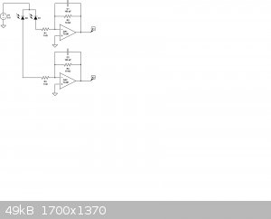
That circuit is a bit scary, but most of it is irrelevant.
|
|
|
Twospoons
International Hazard
Posts: 1282
Registered: 26-7-2004
Location: Middle Earth
Member Is Offline
Mood: A trace of hope...
|
|
That circuit looks like a slightly different sensing principle. The LED appears to be regulated by feedback from one of the photodiodes, probably to
set up a fixed light level for the other photodiode. The photodiode with the 'flag' is part of the servo loop that drives the motor (a torque motor -
same sort of thing as drives the heads in a hard drive). It does not appear to look for light balance between the two photodiodes, but rather
maintain a fixed light level on one photodiode.
The rest of it is a current to voltage converter to turn the motor current into a voltage for the digital meter.
Not scary at all  (apart from the 741 opamps - those are virtually museum
pieces) (apart from the 741 opamps - those are virtually museum
pieces)
Helicopter: "helico" -> spiral, "pter" -> with wings
|
|
|
yobbo II
National Hazard
Posts: 709
Registered: 28-3-2016
Member Is Offline
Mood: No Mood
|
|
I see this module on ebay.
https://www.ebay.co.uk/itm/DS1256-24-Bit-8-Channel-ADC-AD-Mo...
It has an SPI interface.
I will have to start reading up on that . A raspberry pie has SPI. Is it as simply as connecting any SPI interface readout device to the A to D
converter?
For example this item?
https://www.ebay.co.uk/itm/Waveshare-2-23Inch-OLED-Display-H...
Also the A to D converter is only good for signals as high as three volts (2 volts below the devices supply voltage which is 5 volts).
The higher the voltage I am measureing accross the 'output' resistor (the resistor mesureing the current) the better. It gives better resolution
reading 1 to 15v (say) that 0 to3 volts.
TFYT
Yob
|
|
|
Twospoons
International Hazard
Posts: 1282
Registered: 26-7-2004
Location: Middle Earth
Member Is Offline
Mood: A trace of hope...
|
|
As long as you remember that resolution and accuracy are not the same thing.
Helicopter: "helico" -> spiral, "pter" -> with wings
|
|
|
yobbo II
National Hazard
Posts: 709
Registered: 28-3-2016
Member Is Offline
Mood: No Mood
|
|
Thanks for the diagrams Unionised. The thanks is a bit belated!
I attached the following circuit to the balance using the diode position sensor (I believe it is a diode position sensor with a infra red diode
opposite the moving slit)
I am able to obtain a reading for the balance pan suspended in the 'middle' which gives a highest reading on a voltmeter connected between the two op
amp outputs.
I need a better volt meter or (as suggested above) a good A TO D coverter.
Attached is a data sheet for a diode position sensor. It say in the data sheet (bottom of page 3) the following:
Correction for position detection error
Position detection characteristics obtained by the above
formula can be corrected to reduce position detection
errors. For example, the maximum position detection
error (±120 μm) of S3931 can be significantly reduced
to ±9 μm by using the least square method.
What does this mean. How do I do least squares. Where does the data come from?
If you are doing only one measurement then it is impossible?
Yob
Attachment: one_Dimensional_psd.pdf (200kB)
This file has been downloaded 114 times
[Edited on 11-10-2022 by yobbo II]
|
|
|
wg48temp9
National Hazard
Posts: 761
Registered: 30-12-2018
Location: not so United Kingdom
Member Is Offline
|
|
Quote: Originally posted by yobbo II  |
Correction for position detection error
Position detection characteristics obtained by the above
formula can be corrected to reduce position detection
errors. For example, the maximum position detection
error (±120 μm) of S3931 can be significantly reduced
to ±9 μm by using the least square method.
What does this mean. How do I do least squares. Where does the data come from?
If you are doing only one measurement then it is impossible?
[Edited on 11-10-2022 by yobbo II] |
They probable mean that the error can be reduced by using a linear correction curve determined from a multipoint calibration. The correction curve
being determined to produce the least squared error over the measurement range. Its probably not relevant in this application as I assume the sensor
is used to detect only one position.
I am wg48 but not on my usual pc hence the temp handle.
Thank goodness for Fleming and the fungi.
Old codger' lives matters, wear a mask and help save them.
Be aware of demagoguery, keep your frontal lobes fully engaged.
I don't know who invented mRNA vaccines but they should get a fancy medal and I hope they made a shed load of money from it.
|
|
|
Sulaiman
International Hazard
Posts: 3558
Registered: 8-2-2015
Location: 3rd rock from the sun
Member Is Offline
|
|
A few thoughts
To be universally useful,
a balance needs to be calibrated vs an accurately known mass.
In practice several precision weights/masses will be required for interpolation calibration.
Before you go for ultimate resolution electronics;
Decide how you will calibrate your balance,
OIML F1 and F2 are generally adequate
(eg 100g +/- 0.5 and 1.6 mg)
For my 220g x 0.1mg balance I use E2 weights - not cheap.
eg 100g E2 is +/- 0.16mg so can 'calibrate' to +/-0.5mg.
Not much point in having extreme resolution with moderate accuracy.
(I have used the last digit on my balance for statistical improvement of 'accuracy' but it is tedious, mostly I ignore the last digit)
You will want to incorporate 'pid control' in the 'position sensing-to-current' loop.
(unless you are an extremely patient person)
EVERYTHING drifts with temperature and/or time.
PS for a given electro-mechanical system,
accuracy is determined greatly by the stability of the current sensing resistor and the voltage reference.
(A/D, D/A, PWM amplitude etc.)
An interface to printer, pc, phone etc. is very useful.
Attachment: r111-1-e04.pdf (1.1MB)
This file has been downloaded 109 times
[Edited on 12-10-2022 by Sulaiman]
CAUTION : Hobby Chemist, not Professional or even Amateur
|
|
|
Mateo_swe
National Hazard
Posts: 505
Registered: 24-8-2019
Location: Within EU
Member Is Offline
|
|
I would leave the mecanical stuff (it probably works ok) and focus on the electronics.
Check for possible bad solder connections on the circuit board.
Try measure all voltages, the 3 supply voltages you mentioned and any onboard voltage regulator chips and see if you have the correct voltages out
from them.
Often when stuff like this breaks, the fault can be found in the supply voltages or any voltage regulator chips and their support components.
Sometimes it can be the protection components also, like fuses, varistors, supression diodes etc, usually located near where the voltage supply leads
are connected to the board.
A scale like this is worth spending some time on.
|
|
|
unionised
International Hazard
Posts: 5102
Registered: 1-11-2003
Location: UK
Member Is Offline
Mood: No Mood
|
|
Accreditation agencies , very sensibly, say that if you have a balance that reads to a tenth of a microgram, you need to use calibration masses which
are certified (and traceable) to an accuracy of better than a tenth of a microgram.
I once had an entertaining time explaining to an assessor that we couldn't do that with our microbalance.
The assessment was undertaken by UKAS (a subsidiary of the national physical laboratory).
I said I had contacted the NPL and they couldn't certify test masses to that precision. Since they couldn't, it was unlikely that anyone on the planet
could.
But I was still able to convince them the balance was OK.
You can buy certified 1 milligram test masses (give or take 3 micrograms).
And I could weigh out samples of dye and dissolve the dye and measure the colour and that was good enough to demonstrate the linearity of the balance.
And I verified the linearity with very small bits of foil.
I was able to show that the precision of the balance was better than the accuracy of the test / calibration masses.
Everything drifts with temperature- that's why balances like these have built in heaters and thermostats.
|
|
|
yobbo II
National Hazard
Posts: 709
Registered: 28-3-2016
Member Is Offline
Mood: No Mood
|
|
Thanks for replys.
I have looked around the electronics but they are way beyond me.
I can purchase the two boards (there are three boards in the machine in total). here but I don't know what board that is broken.
https://www.ebay.co.uk/itm/255670676929?hash=item3b8728edc1:...
https://www.ebay.co.uk/itm/255670676211?hash=item3b8728eaf3:...
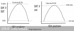
I have been reading the 'center sensing' linear position photo diode using the circuit on my last post and I get the following voltages from the two
op amps.
I need either a voltmeter with more decimal places (expensive) or I was thinking to put a log amplifier onto the output of the two op amps (circuit
above in last post) in order to stretch the peak of the curve so that I can obtain the 'balance center' more accurately.
Then I need to get another circuit to read the current accurately in the coil that holds the balance at the center point.
I need to obtain the balance point (center point) accurately first.
I am moving the balance 'beam' using a potentiometer in series with the force coil for now.
Can anyone suggest a log amplifier (op amp) circuit that would do this job?
Will look on the net in the mean time.
Can anyone suggest what would be a safe current to put through the IR LED (on the opposite side of the slit to the position photodiode) . You get a
more exact center point (the diagrams are very crude) when you increase the current (brightness).
Yob
[Edited on 12-10-2022 by yobbo II]
|
|
|
yobbo II
National Hazard
Posts: 709
Registered: 28-3-2016
Member Is Offline
Mood: No Mood
|
|
at Sulaiman
Reading from your attached file:
For class E1 weights, the density of air should always be determined based on corresponding measurements. However,
the following approximation equation is a way to estimate the air density at laboratories that have no means
of determining the air density at the site. The height above sea level is always known. Therefore, if the air density is
not measured, it should be calculated as a mean value for the laboratory site as follows:
(formula not included in copy and paste)
Will ya hold on till I get a bell on me bike!!
Cheers,
Yob
|
|
|
| Pages:
1
2 |


