| Pages:
1
2 |
Fulmen
International Hazard

Posts: 1693
Registered: 24-9-2005
Member Is Offline
Mood: Bored
|
|
Stability and precision of Hall-based current sensors?
I'm planning a little Arduino-project, building a data-logger for measuring efficiency of a heat pump. This means measuring both voltage and current
on 220V AC.
I can get suitable current transformers, but it seems like I have to make the interface myself. Shouldn't be too hard, some impedance matching and a
little bias to get a DC signal.
On the other hand I can get ready made Hall-based sensors, but I'm not sure how sensitive they are to the surrounding magnetic field. Will this be a
major nuisance in real-world application?
The rest of the unit seems fairly simple, voltage can be measured through a voltage divider (biased to DC). And temperature sensors come in all
possible types imaginable. I'm going for K-elements as I have several probes (and a furnace) using it. Besides my beloved 2-chhannel K-thermometer
crapped put, and I realized I could build a better unit myself. With the arduino I can add a data logger for 5$.
We're not banging rocks together here. We know how to put a man back together.
|
|
|
Sulaiman
International Hazard
Posts: 3554
Registered: 8-2-2015
Location: 3rd rock from the sun
Member Is Offline
|
|
Hall sensors drift in gain and offset over time,
these types of current sensor are common and clever
https://uk.rs-online.com/web/p/current-transducers/4362330/
the datasheet gives a good overview of the technology.
You supply +/- dc voltage and the third terminal is a voltage representation of the current to be measured/monitored,
internally they pass a current through a winding to keep the flux in the core at zero,
the core has a slot in it where a Hall sensor monitors the flux density.
The output voltage is proportional to the current in the winding which is proportional to the current being monitored.
There are many types and manufacturers offering different bandwidths, offsets etc.
Here in UK the brand LEM is to current transducers as Xerox is to photocopiers, or Biro to ballpen.
https://www.lem.com/en
Just in case it is not obvious, with a '20A' sensor,
full voltage outout will be at +/- 20 A if the wire being sensed passes through the hole once,
or at +/- 2 A if ten turns of thinner wire are used.
i.e. the hole senses amp.turns.
[Edited on 13-11-2018 by Sulaiman]
|
|
|
Fulmen
International Hazard
Posts: 1693
Registered: 24-9-2005
Member Is Offline
Mood: Bored
|
|
Looks like Hall-sensors are out. I like the sensor you linked to, but these are cheaper and easier to get:
https://www.dx.com/p/10a-1v-split-core-current-transformer-a...
I also noticed that this ADC should be able to measure negative input:
https://www.dx.com/p/16-bit-i2c-ads1115-module-adc-4-channel...
That simplifies wiring while also providing better resolution. Seems like a simple PnP-solution.
We're not banging rocks together here. We know how to put a man back together.
|
|
|
Fulmen
International Hazard
Posts: 1693
Registered: 24-9-2005
Member Is Offline
Mood: Bored
|
|
I could go for something like this (the current transformer would get a similar bias):
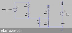
But by using this:
https://www.dx.com/p/16-bit-i2c-ads1115-module-adc-4-channel...
I can actually measure the straight AC signal using differential input. And at a better resolution then the board.
We're not banging rocks together here. We know how to put a man back together.
|
|
|
Twospoons
International Hazard
Posts: 1280
Registered: 26-7-2004
Location: Middle Earth
Member Is Offline
Mood: A trace of hope...
|
|
Have you considered some of the ASICs intended for exactly this purpose?
https://www.analog.com/en/parametricsearch/10577
Helicopter: "helico" -> spiral, "pter" -> with wings
|
|
|
Fulmen
International Hazard
Posts: 1693
Registered: 24-9-2005
Member Is Offline
Mood: Bored
|
|
Not really. A bit too advanced for me now, besides I have other uses for these components so the Arduino-route seems like the logical choice.
We're not banging rocks together here. We know how to put a man back together.
|
|
|
DavidJR
National Hazard
Posts: 908
Registered: 1-1-2018
Location: Scotland
Member Is Offline
Mood: Tired
|
|
Do not forget that with AC you cannot simply measure RMS voltage and RMS current and then multiply - this gives the apparent power, which in many
cases, may be significantly higher than the real power, depending on the load's power factor. Only for purely resistive loads are real and apparent
power equal. Inductive or capacitive loads cause a shift in phase between the current and voltage waveform which throws off the power factor. And
nonlinear loads - which are extremely common nowadays with switched mode power supplies - may result in totally non-sinusoidal waveforms which makes
it even more difficult.
The correct way to do it is to sample instantaneous voltage and instantaneous current at a frequency significantly higher than the mains frequency -
I'd say at least 10x but faster is better - then multiply to get an instantaneous power waveform. You can then compute the RMS power from this
waveform and get an accurate measurement of real power.
|
|
|
Fulmen
International Hazard
Posts: 1693
Registered: 24-9-2005
Member Is Offline
Mood: Bored
|
|
David: That's exactly what I'm planning. The ADC has a max sample rate of 860sps, should be enough to measure 50Hz.
We're not banging rocks together here. We know how to put a man back together.
|
|
|
DavidJR
National Hazard
Posts: 908
Registered: 1-1-2018
Location: Scotland
Member Is Offline
Mood: Tired
|
|
Quote: Originally posted by Fulmen  | | David: That's exactly what I'm planning. The ADC has a max sample rate of 860sps, should be enough to measure 50Hz. |
Yes, that should be more than enough. However:
Ideally you want the samples for a pair of voltage/current measurements to be taken as close to simultaneously as possible. If you use the input
multiplexing of the ADS1115, then not only will your effective sample rate be halfed to 430sps but you will also introduce a phase error in the
measurements.
In this case the time elapsed from one reading to the next is 1/860s = 1.16ms. Assuming 50Hz input (which has T=1/50s=20ms) then this is 5.8% of a
cycle. In other words, this is a phase error of 20.88 degrees.
That's a bit too high for my liking. How much of an error in final power reading that will cause depends on the load, of course. I'd either use two
independent synchronized ADCs to get truly simultaneous sampling; or alternatively pick an ADC with a much higher sampling rate such that the phase
error is acceptably low.
[Edited on 14-11-2018 by DavidJR]
|
|
|
Vomaturge
Hazard to Others
Posts: 285
Registered: 21-1-2018
Member Is Offline
Mood: thermodynamic
|
|
If you're making your own current sensor, you could also just put a low value resistor (preferably a few percent or less of the load impedance) in
series with the load, and measure the voltage across that. Keep in mind that the whole voltage measuring circuit will be at 110* volts above ground
voltage, so don't connect any other grounded circuits (power supplies, displays, etc.) to it, and certainly don't touch it But, if you can easily isolate this "shunt resistor" (and the circuit reading its
voltage) from the data logger, then this is probably the simplest current transducer there is. But, if you can easily isolate this "shunt resistor" (and the circuit reading its
voltage) from the data logger, then this is probably the simplest current transducer there is.
*I'm assuming you have a US style electrical service, with a grounded center tap and two "live" conductors which are at 110vac relative to ground, and
220vac relative to each other.
|
|
|
DavidJR
National Hazard
Posts: 908
Registered: 1-1-2018
Location: Scotland
Member Is Offline
Mood: Tired
|
|
| Quote: Originally posted by Vomaturge |
*I'm assuming you have a US style electrical service, with a grounded center tap and two "live" conductors which are at 110vac relative to ground, and
220vac relative to each other. |
Given that they mentioned they are in a 50Hz country using 220VAC it is incredibly unlikely that they have a bizzarre US-style two-phase supply.
|
|
|
Vomaturge
Hazard to Others
Posts: 285
Registered: 21-1-2018
Member Is Offline
Mood: thermodynamic
|
|
Oops. Didn't notice the 50Hz part. In the US, a big load like a heat pump uses both phases, and that is sometimes called "220v," but the voltage is
supposed to be 240v, and is not usually supposed to drop below 228v under load (233v for lighting circuits). Seems like a lot of switches and fixtures
have "125v" and "250v" ratings, just to be sure. I debated whether to say "240v" or "220v" in my post; one would fit with what Fulmen called his
supply (50Hz aside,) and what many Americans call the big outlets behind the stove and clothes dryer, while the other would be what the US mains is
officially supposed to be.
Anyhow, if your outlet has 220v with one terminal grounded, definately put the shunt resistor on that side of the load. But remember that this neutral
terminal can still gain voltage relative to ground if it gets disconnected from ground for any reason. It happens more than you might think!
Why am I recommending a shunt, and then saying it's dangerous? Because it's good in certain applications. In a mains powered sensor inside a closed
case, it should be just fine. The more options the merrier, and in the end, only Fulmen can narrow them down based on what other parts of the unit he
can design around the sensor, vs what parts the sensor must be designed around (or selected, more likely. Just another suggestion how to avoid
integrating a current transformer or calibrating a finicky hall sensor.
|
|
|
Fulmen
International Hazard
Posts: 1693
Registered: 24-9-2005
Member Is Offline
Mood: Bored
|
|
David: You make a good point. Using the bias circuit I can use the internal ADC, 10bit should be accurate enough.
There are also better ADCs out there, like this one: http: //mayhewlabs.com/products/extended-adc-shield
Yes, it's 230V/50hz single phase. I'd rather not use a shunt as the heat pump is permanently wired.
We're not banging rocks together here. We know how to put a man back together.
|
|
|
Twospoons
International Hazard
Posts: 1280
Registered: 26-7-2004
Location: Middle Earth
Member Is Offline
Mood: A trace of hope...
|
|
So you ideally want a split core CT, or perhaps a Rogowski coil. The second option is a little more complex as it needs an integrator.
Helicopter: "helico" -> spiral, "pter" -> with wings
|
|
|
wg48
National Hazard
Posts: 821
Registered: 21-11-2015
Member Is Offline
Mood: No Mood
|
|
| Quote: Originally posted by Twospoons |
So you ideally want a split core CT, or perhaps a Rogowski coil. The second option is a little more complex as it needs an integrator.
|
Can someone explain the functional difference between a current transformer and a Rogowski coil?
I know what the difference in construction is . In particular that the to toroidal winding is not complete ie the winding does not form a single turn
round the conductor being sensed. In typical description of Rogowski coils that is emphasised which appears to be a practicality but irrelevant to its
function.
Putting it differently is Rogowski coil nothing more than air cored current transformer operated with a high impedance load on its sense winding
unlike the usual low impedance load of a current transformer?
Borosilicate glass:
Good temperature resistance and good thermal shock resistance but finite.
For normal, standard service typically 200-230°C, for short-term (minutes) service max 400°C
Maximum thermal shock resistance is 160°C
|
|
|
Fulmen
International Hazard
Posts: 1693
Registered: 24-9-2005
Member Is Offline
Mood: Bored
|
|
Twospoons: I did glance at Rogowski-coils, and while they look simple enough in theory I expect it will take some time to figure out the optimal
design. So I'll start with a ready-made CT and keep the Rogowski for future experiments.
We're not banging rocks together here. We know how to put a man back together.
|
|
|
Twospoons
International Hazard
Posts: 1280
Registered: 26-7-2004
Location: Middle Earth
Member Is Offline
Mood: A trace of hope...
|
|
| Quote: Originally posted by wg48 |
Putting it differently is Rogowski coil nothing more than air cored current transformer operated with a high impedance load on its sense winding
unlike the usual low impedance load of a current transformer?
|
Pretty much. Except that with the Rogowski coil the terminal voltage is proportional to dI/dt - hence the need for the integrator. The other major
difference is the Rogowski will present a much smaller load on the circuit being measured.
The lack of a rigid core can also be a big advantage in some situations.
I'd imagine the Rogowski coil would be a much cheaper option where you have to measure current in a really fat cable - big ferrite cores don't come
cheap.
[Edited on 15-11-2018 by Twospoons]
Helicopter: "helico" -> spiral, "pter" -> with wings
|
|
|
Fulmen
International Hazard
Posts: 1693
Registered: 24-9-2005
Member Is Offline
Mood: Bored
|
|
Progress so far: I want to do a "feasibility-test" before ordering components, so I have started with the voltage measurements. I ended up using a 24V
transformer and a 1:10 divider, and except for some weird waveforms it seems to be working. The real challenge seems to be data transfer. Even at 115k
dumping each measurements pair (A0 and millis) causes excessive delays, so I've opted for reading multiple measurements into an array and then
transmit that package. A set of 50 reads seems to take appr. 0.08ms, so in the range of 10ksps.
So far it seems to be doable without too much work. Next is to test a prototype ct. I will of course buy a spit-core once I know what I need, but
winding a solid core for testing purposes shouldn't be too hard. Will ferrite cores work?
We're not banging rocks together here. We know how to put a man back together.
|
|
|
Sulaiman
International Hazard
Posts: 3554
Registered: 8-2-2015
Location: 3rd rock from the sun
Member Is Offline
|
|
If you are in a mood to wind 1000 or so turns on a small ferrite toroid then ok
if not then just buy some of these;
https://www.ebay.co.uk/itm/5Pcs-Current-Transformer-Sensor-M...hcAAOSwxLdb1dXr
basically a (MnZn) ferrite toroid with 10A/5ma = 2000 turns.
CAUTION : Hobby Chemist, not Professional or even Amateur
|
|
|
Twospoons
International Hazard
Posts: 1280
Registered: 26-7-2004
Location: Middle Earth
Member Is Offline
Mood: A trace of hope...
|
|
Not hard, just unbelievably tedious to do by hand. Especially using fine wire.
Yes they should.
Really they are cheap enough to just buy one, and save yourself a lot of time. I wouldn't bother making one unless you need something special.
What do you mean by "weird waveforms"? You should be getting sine waves. If not then something is out of wack.
[Edited on 16-11-2018 by Twospoons]
Helicopter: "helico" -> spiral, "pter" -> with wings
|
|
|
Fulmen
International Hazard
Posts: 1693
Registered: 24-9-2005
Member Is Offline
Mood: Bored
|
|
Most definitively. But I just threw the circuit together using a very long cable so I might be picking up some stray signals. I'll rework the circuit
to see if that solves the problem.
I also got another problem, after reworking the code it no longer reads the voltage. This is my current code:
| Code: |
void loop() {

  int n=20;  //   Array size
  int f=1;   //   Delay per cycle
  int s=1;   //  Delay per array

  int voltage[n]={0};
  int current[n]={0};
  int timestamp[n]={0};

  for (int i=0; i<n; i++){
    voltage[i]=analogRead(A0);
    current[n]=analogRead(A1);
    timestamp[i]=millis();
    delay(f);
  }

  for (int i=0; i<n; i++){
  Serial.print(timestamp[i]);
  Serial.print("\t");
  Serial.print(current[i]);
  Serial.print("\t");
  Serial.println(voltage[i]);
   }
   Serial.println();
  delay(s);
}
|
Edit: Never mind, found it: current[n]
That's a weird one, it worked before the rewrite and I didn't touch the for-loops. Oh well...
[Edited on 17-11-18 by Fulmen]
We're not banging rocks together here. We know how to put a man back together.
|
|
|
Fulmen
International Hazard
Posts: 1693
Registered: 24-9-2005
Member Is Offline
Mood: Bored
|
|
Arduino power meter (was: Stability of Hall-based...)
I also changed A1 to A0, reading the voltage twice until I get a ct. Here's the resulting data:
Attachment: logg.csv (3kB)
This file has been downloaded 517 times
[Edited on 17-11-18 by Fulmen]
We're not banging rocks together here. We know how to put a man back together.
|
|
|
Sulaiman
International Hazard
Posts: 3554
Registered: 8-2-2015
Location: 3rd rock from the sun
Member Is Offline
|
|
Some bits of relevant information ;
. the linear output voltage range of a current transformer is limited.
The small c.t. that I pointed to for example is specified for a burden resistance <= 250 Ohms
so maximum output voltage is 1.25 Vrms to maintain linearity.
. you could use 50 Ohm co-ax cable with 50 Ohms terminating each end of the cable.
This would give a nett burden resistance of 25 Ohms,
with an output of 125 mVrms representing 10 Arms sensed.
The cable would be shielded against noise and terminated against reflections.
. the maximum usable output voltage increases proportional to frequency,
. operating frequency is limited by the MnZn core and/or self-resonance.
CAUTION : Hobby Chemist, not Professional or even Amateur
|
|
|
Vomaturge
Hazard to Others
Posts: 285
Registered: 21-1-2018
Member Is Offline
Mood: thermodynamic
|
|
| Quote: Originally posted by Sulaiman |
you could use 50 Ohm co-ax cable with 50 Ohms terminating each end of the cable.
This would give a nett burden resistance of 25 Ohms,
with an output of 125 mVrms representing 10 Arms sensed.
The cable would be shielded against noise and terminated against reflections
|
You're treating it like a transmission line (traveling waves). The transformer's output is 50Hz, and is being carried a few tens of meters as far as I
know. Even a whole kilometer of coax cable is about .025% as long as a 50Hz wave inside it. There's just not enough inductance and capacitance to make
a noticeable impedance or reflection for such a short run and such a low frequency.
Edit: Although the inductance/capacitance/transit time of his cable isn't a problem, shielding from external noise is a good idea, if a shorter cable
can't be used.
[Edited on 17-11-2018 by Vomaturge]
|
|
|
Fulmen
International Hazard
Posts: 1693
Registered: 24-9-2005
Member Is Offline
Mood: Bored
|
|
You and I might have different definitions of tedious. I just did 100 turns because there wasn't anything good on TV.
We're not banging rocks together here. We know how to put a man back together.
|
|
|
| Pages:
1
2 |


