| Pages:
1
..
30
31
32
33
34
..
68 |
Hennig Brand
International Hazard
    
Posts: 1284
Registered: 7-6-2009
Member Is Offline
Mood: No Mood
|
|
I have moved the post regarding electroforming copper cones to the thread "Electroforming Copper Cones". The post gives a description with pictures of
aluminum electroplating forms which were turned on a lathe. If and when I test some of the copper cones I will post the results of that here.
|
|
|
gnitseretni
Hazard to Others
  
Posts: 280
Registered: 5-1-2007
Location: Medellin
Member Is Offline
Mood: No Mood
|
|
Nice to see someone's still doing some experimenting with shaped charges 
Can't wait to see the performance of your electroformed cones. Should do better than mine as mine weren't plated onto a machined form. The next one
will be though, as I got me a lathe now too 
|
|
|
Hennig Brand
International Hazard
    
Posts: 1284
Registered: 7-6-2009
Member Is Offline
Mood: No Mood
|
|
It was a friend's lathe actually. I have been keeping an eye open for one of my own for a while though. It takes a bit of time, but it is very easy to
make an aluminum cone on a lathe. Working with aluminum is not nearly as hazardous as working with steel, which is another nice benefit. For example
you can easily pick up a big handful of the aluminum turnings with your bare hands and not worry about getting cut, something you wouldn' t want to
risk with most steel turnings. Aluminum also cuts very easily relative to steel. I think you will have a lot of fun with your lathe.
[Edited on 12-9-2011 by Hennig Brand]
|
|
|
Hennig Brand
International Hazard
    
Posts: 1284
Registered: 7-6-2009
Member Is Offline
Mood: No Mood
|
|
I haven't tested an electroformed copper liner yet because I am in the city right now. Hopefully I will get the chance soon.
The following is a copy/past from "A Brief Histroy of Shaped Charges", by William Walters. A pdf of the full report is also included. The copy/paste
is supposedly some of the results of Japanese study on shaped charges around the time of the second world war.
"The Japanese also
concluded that a hole in the apex of a conical or hemispherical liner was desirable.
Also, the size of this hole was critical, an optimal value for the apex hole diameter
being 1/10 of the warhead charge diameter. (The wall thickness was taken as 1/25
of the charge diameter and the liner diameter was taken to be 4/5 of the charge
diameter for both conical and hemispherical liners.) The optimal cone apex angle
was determined to be between 35° and 50°. The optimal open apex diameter was
concluded to be 3/16 of the charge diameter for this warhead."
I am particularly interested in finding an optimal liner thickness for copper. Does what they report seem reasonable?
Attachment: A Brief History of Shaped Charges.pdf (97kB)
This file has been downloaded 1381 times
[Edited on 18-9-2011 by Hennig Brand]
|
|
|
VladimirLem
Hazard to Others
  
Posts: 204
Registered: 24-5-2010
Member Is Offline
Mood: Have no fear <Vlad> is here.
|
|
Quote: Originally posted by Hennig Brand  |
I am particularly interested in finding an optimal liner thickness for copper. Does what they report seem reasonable?
[Edited on 18-9-2011 by Hennig Brand] |
Yes...the infos seems okay...
@liner-thickness:
i would go for this:
6-7cm CD Shaped charge using TNT - 1.25mm (Cu)
7-8cm CD Shaped charge using TNT - 1.50mm (Cu)
8-10cm CD Shaped charge using TNT - 2.00mm (Cu)
10-14cm CD Shaped charge using TNT - 2.50mm (Cu)
Using PETN/RDX, all Liners +0.25mm
|
|
|
Hennig Brand
International Hazard
    
Posts: 1284
Registered: 7-6-2009
Member Is Offline
Mood: No Mood
|
|
Thanks for the reply, but unless I missed something the numbers for liner thicknesses seem about half what they should be. It seems like you stated CD
(charge diameter), and then proceeded to take approximately 1/25 of the charge radius, or 1/25 of half the diameter.
[Edited on 18-9-2011 by Hennig Brand]
|
|
|
gnitseretni
Hazard to Others
  
Posts: 280
Registered: 5-1-2007
Location: Medellin
Member Is Offline
Mood: No Mood
|
|
I found a small txt file a long time ago that says thickness of cone is 0.032 x CD (in mm).
So for a 1" (25.4 mm) cone, thickness would be: 0.032 x 25.4 = 0.81 mm.
Whether that formula gives the optimal liner thickness, I don't know.
|
|
|
VladimirLem
Hazard to Others
  
Posts: 204
Registered: 24-5-2010
Member Is Offline
Mood: Have no fear <Vlad> is here.
|
|
Quote: Originally posted by Hennig Brand  | Thanks for the reply, but unless I missed something the numbers for liner thicknesses seem about half what they should be. It seems like you stated CD
(charge diameter), and then proceeded to take approximately 1/25 of the charge radius, or 1/25 of half the diameter.
[Edited on 18-9-2011 by Hennig Brand] |
the liner-thickness is just at a rough guess...
yes, ists hard to find good sources for liner-thickness
maybe i find a good pdf at my harddrive, the i upload it...
|
|
|
Hennig Brand
International Hazard
    
Posts: 1284
Registered: 7-6-2009
Member Is Offline
Mood: No Mood
|
|
Well 1/25 CD is 0.04 CD, so your 0.032 CD is not too far off the Japanese numbers I guess. I don't have this down to an exact science yet anyway so as
long as I am in the ball park I am happy. The ratio for optimal liner thickness most likely varies with other parameters as well, like charge size and
liner material perhaps. In VladimirLem's post, a couple of posts ago, the liner thickness values had an amount added if the more brisant explosives
were used. I think I will aim for between 0.03 and 0.04 CD, thanks.
[Edited on 19-9-2011 by Hennig Brand]
|
|
|
VladimirLem
Hazard to Others
  
Posts: 204
Registered: 24-5-2010
Member Is Offline
Mood: Have no fear <Vlad> is here.
|
|
Hi Guys
The value of 0.03 CD seems a bit many - especially at the smaller CD-Charges !
1.8mm at 60mm is a lot ! I would only go for that with really powerfull stuff AND by the way - better you take a bit too thin liner that a bit to big
! If too thin, you get a (super) high velocity jet BUT if too big, the performace and velocity will go extreamly down !
i would use 0.025 CD for PETN<
|
|
|
nitro-genes
International Hazard
    
Posts: 1048
Registered: 5-4-2005
Member Is Offline
|
|
Wall thickness is probably optimized for:
1. Detonation pressure of explosive (higher = thicker liner)
2. Density of liner material (higher = thinner liner)
3. Speed of sound in liner material (higher is thinner liner)
My guess would be that a shaped charge is mostly a tradeoff between these 3 factors, chosen in such a way that the liner is not accelerated beyond the
speed of sound for the material under the pressures during the detonation (~1.2x compared to ambient pressures) and that the resulting jettip has the
highest velocity possible. Cone angle and charge design also have an effect on jettip and liner collapse velocity, EFP for example use somewhat
thicker liners, though I'm not sure whether a general rule exist for this. :-)
When in doubt of your liner or charge precision, 3% will probably do better than 2% of CD for materials in the density range of copper
|
|
|
gnitseretni
Hazard to Others
  
Posts: 280
Registered: 5-1-2007
Location: Medellin
Member Is Offline
Mood: No Mood
|
|
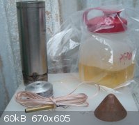
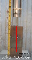
Did another shaped charge.
There's about 225ml PGDN in that container in the picture, but used about 200ml of it.
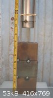
The cone was the last one I had. Diameter was 1.89". Unsure of exact angle, but I guesstimate it to be about 75-80 degrees. It was plated onto a
non-machined form (fence post cap). The cone was off-round and it's thickness was non-uniform. I only measured at the base as I only have calipers (no
micrometer) and it was 1.46mm on one side and 1.64mm on the other side. The stainless steel tube was off-round as well. The only thing that was
machined was the top to center the detonator. I only did that because I can use the practice 
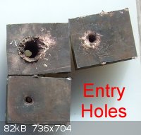
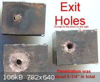
Total penetration was 6-1/4". I'm satisfied 
EDIT: Forgot to mention standoff, which was 3".
Video really sucks, but here it is anyway..
http://www.youtube.com/watch?v=XqhA0FeVfEo
[Edited on 10-16-2011 by gnitseretni]
|
|
|
Bot0nist
International Hazard
    
Posts: 1559
Registered: 15-2-2011
Location: Right behind you.
Member Is Offline
Mood: Streching my cotyledons.
|
|
Wow, That's impressive!
That big jug of PGDN makes me nervous, lol.
U.T.F.S.E. and learn the joys of autodidacticism!
Don't judge each day only by the harvest you reap, but also by the seeds you sow.
|
|
|
Formatik
National Hazard
   
Posts: 927
Registered: 25-3-2008
Member Is Offline
Mood: equilibrium
|
|
That's a pretty interesting result gnitseretni. What are those metal blocks made out of?
|
|
|
gnitseretni
Hazard to Others
  
Posts: 280
Registered: 5-1-2007
Location: Medellin
Member Is Offline
Mood: No Mood
|
|
Just regular mild steel I think.
EDIT: I think more standoff would've improved penetration. I mean, look at that big entry hole. Making an inch wide hole takes more effort than a half
inch hole, so that big entry hole must have slowed down the jet some (substantially?). By increasing standoff I would have given the cone more
distance to stretch, making the jet narrower, which would have resulted in a smaller entry hole. And this decrease in resistance would have improved
penetration. Or that's my theory anyway, and I'm sticking to it 
[Edited on 10-16-2011 by gnitseretni]
|
|
|
hissingnoise
International Hazard
    
Posts: 3940
Registered: 26-12-2002
Member Is Offline
Mood: Pulverulescent!
|
|
| Quote: | | That big jug of PGDN makes me nervous, lol. |
And the yellow colour doesn't inspire too much confidence in its keeping qualities!
|
|
|
VladimirLem
Hazard to Others
  
Posts: 204
Registered: 24-5-2010
Member Is Offline
Mood: Have no fear <Vlad> is here.
|
|
Quote: Originally posted by gnitseretni  | Just regular mild steel I think.
EDIT: I think more standoff would've improved penetration. I mean, look at that big entry hole. Making an inch wide hole takes more effort than a half
inch hole, so that big entry hole must have slowed down the jet some (substantially?). By increasing standoff I would have given the cone more
distance to stretch, making the jet narrower, which would have resulted in a smaller entry hole. And this decrease in resistance would have improved
penetration. Or that's my theory anyway, and I'm sticking to it 
[Edited on 10-16-2011 by gnitseretni] |
You're right...just look some technical pictures at Google-images about the russian RPG-Series warheads...
The Standoff value is most times far about 2,5 CD.
With a coppercone (all pure metal-cones), no problem...just for improvised liners (glass etc) i would go for smaler Standoffs like around 1.5CD
and yes...the thinner the penetration-hole, less energy is lost and will increase the penetration dept much !
|
|
|
hissingnoise
International Hazard
    
Posts: 3940
Registered: 26-12-2002
Member Is Offline
Mood: Pulverulescent!
|
|
The cone height-to-radius needs to be factored in too, BTW!
|
|
|
gnitseretni
Hazard to Others
  
Posts: 280
Registered: 5-1-2007
Location: Medellin
Member Is Offline
Mood: No Mood
|
|
The color is because of the sulfuric acid I used (drain cleaner).
Hey Hiss, your turn for a SC is way overdue amigo  Come on, help keep this
thread alive! Come on, help keep this
thread alive!
|
|
|
watson.fawkes
International Hazard
    
Posts: 2793
Registered: 16-8-2008
Member Is Offline
Mood: No Mood
|
|
What strikes me about these pictures is how clearly visible is the heat-affected
zone of the metal. It extends all the way to the edges of the top sample. It seems clear to me that it's compression heating of the metal. Surface
oxides from the heat are just like what you get from tempering heats.
The edges of that top block are really obviously no longer straight. You're well into the elastic deformation range of forces outward from the
penetration path.
You're right at the edge of getting useful quantitative results from these tests. All that's needed is to standardize the test target. The reason for
standardization should be obvious. Picking an alloy number would be useful too. 1018 is the most common cold-rolled steel. It's very possible that's
what you've got there already.
I'd recommend enlarging the targets to minimize the bulk deformation. This would reflect better what actual penetration into plate would look like.
I'd say squares of 6" or so on edge. You want squares to that you measure total permanent deformation. I'm sure that even with 6" you'd be able to
pick up the bulging with a dial indicator.
|
|
|
VladimirLem
Hazard to Others
  
Posts: 204
Registered: 24-5-2010
Member Is Offline
Mood: Have no fear <Vlad> is here.
|
|
Hi guys
Im a bit confused of non reading a single "peripherally initiated" chaped charge at this thread.
So i present you my "researches" with them.
It started with looking at a technical drawing of a "Panzerfaust 3" Tandemshaped charge warhead - i wondered why there is a secon cavity inside the
maincharge. I knew that couldnt be a drawing-mistake or someting else and came to the point that the detonation wave goes throug the thin explosive at
the cavity and then ignited the charge - look at my drawings.


This makes that many detonation pressure goes direct to the liner.
And not like a "normal" shaped charge, where amny detonationpressure goes to the outside and not direktly to the cone (drawing 3)...

Now imagine the shaped charge that one dude made with the PETN/NG and the huge coppercone which penetrated over 40cm steel - HOW many power it would
get with this method - i say up to 60cm are no problem !
I tested it some times...the first failed a bit cause of a assymetric building...the second - 1,0kg ANNM-AL with not really good quallity and a
glassline penetrated a 5cm Steelplate...


Download US Patent 5565644 and take a look at "Fig. 1"
It works, and it increases the penetration ALOT 
|
|
|
Username
Harmless

Posts: 7
Registered: 13-9-2009
Member Is Offline
Mood: No Mood
|
|
The principle you're talking about is the use of waveshapers.
nitro-genes mentioned the use of them on page 19 of this thread. He used epoxy resin to form the inert-filled cavity in the explosive.
|
|
|
hissingnoise
International Hazard
    
Posts: 3940
Registered: 26-12-2002
Member Is Offline
Mood: Pulverulescent!
|
|
| Quote: | Hey Hiss, your turn for a SC is way overdue amigo  Come on, help keep this
thread alive! Come on, help keep this
thread alive! |
Uh, plans in the pipeline - you know how it is . . . ?
|
|
|
gnitseretni
Hazard to Others
  
Posts: 280
Registered: 5-1-2007
Location: Medellin
Member Is Offline
Mood: No Mood
|
|
You're right. That top block is pretty deformed. I think that if I had used a larger block (like you suggest I do next time) that penetration would
have been less. Would you agree? Ah, I guess there's only one way to find out for sure 
Quote: Originally posted by watson.fawkes  | What strikes me about these pictures is how clearly visible is the heat-affected
zone of the metal. It extends all the way to the edges of the top sample. It seems clear to me that it's compression heating of the metal. Surface
oxides from the heat are just like what you get from tempering heats.
The edges of that top block are really obviously no longer straight. You're well into the elastic deformation range of forces outward from the
penetration path.
You're right at the edge of getting useful quantitative results from these tests. All that's needed is to standardize the test target. The reason for
standardization should be obvious. Picking an alloy number would be useful too. 1018 is the most common cold-rolled steel. It's very possible that's
what you've got there already.
I'd recommend enlarging the targets to minimize the bulk deformation. This would reflect better what actual penetration into plate would look like.
I'd say squares of 6" or so on edge. You want squares to that you measure total permanent deformation. I'm sure that even with 6" you'd be able to
pick up the bulging with a dial indicator. |
|
|
|
watson.fawkes
International Hazard
    
Posts: 2793
Registered: 16-8-2008
Member Is Offline
Mood: No Mood
|
|
Quote: Originally posted by gnitseretni  | | You're right. That top block is pretty deformed. I think that if I had used a larger block (like you suggest I do next time) that penetration would
have been less. Would you agree? Ah, I guess there's only one way to find out for sure |
I don't know. I came
up with arguments going both ways. One one hand, your test blocks might exhibit less penetration than into an "infinite plate". You're expending
energy with inelastic deformation of the steel. Jet confinement isn't as good in the first block, loosening the pulse confinement and broadening it.
On the other hand, it might be more, because a small block might act like a thinner block, more flexible and getting out of the way. As you say,
testing is required.
Another deviation from ideal behavior is the way you've stacked up plates. It looks like the gap between the first and second plate bulged out like a
disc-shaped balloon, allowing a gap between them and surface spalling. Using a solid test block, though, is only viable if you don't care about
dissection and don't have a metal-cutting bandsaw. What you've done with tack-welds seems like a decent compromise.
|
|
|
| Pages:
1
..
30
31
32
33
34
..
68 |