| Pages:
1
..
3
4
5
6
7
8 |
Magpie
lab constructor

Posts: 5939
Registered: 1-11-2003
Location: USA
Member Is Offline
Mood: Chemistry: the subtle science.
|
|
epoxy paint source
Since some members are having difficulty sourcing epoxy paint for their fume hoods or work surfaces I thought I would post these:
http://www.rustoleum.com/CBGProduct.asp?pid=116
http://www.armorpoxy.com/bath-and-kitchen/for-dummies-refini...
These products are available in the 1 quart size. I think I bought mine (Rust-Oleum) at Home Depot or possibly Lowe's. I used it to paint a plywood
work surface before I built my hood. I can recommend it to anyone needing a small quantity of a 2-part epoxy paint.
I realize these products may only be available in the US, but hopefully similar products are available where you live.
For my hood I bought a gallon of 2-part epoxy paint from Sherwin-Williams, a paint dealer. The painted hood surfaces are as good as new after 3-4
years of use. The unpainted aluminum baffles, however, show battle scars from hot hydroxides.
[Edited on 14-4-2009 by Magpie]
|
|
|
EmmisonJ
Hazard to Self
Posts: 89
Registered: 5-1-2009
Member Is Offline
Mood: No Mood
|
|
i'm trying to think of ideas on how i can implement a sash.
my fume hood is just a wooden storage cabinet like this (no wheels)

i modified it so that i can put baffles in it (currently working on) and also modified it so that there is a shelf half-way through. below the shelf
is storage for glass (tight on space) and above the shelf is the fume hood work area. so making a sash is kind of difficult because of the doors to
the cabinet which i want to leave on there. i figured my only way of making a sash that works inside of this cabinet without interfering with the
doors is one of two ways. either way, the glass will be held in place by using a sliding door lock. this is a great idea i saw someone else on here
do in a fumehood post.
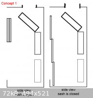
the first picture shows a side view of the first concept which i want to pursue but am unsure of how to realistically pull off the concept. basically
the 3 squares where the sash is are representative of 3 glass panes, all lined up one in front of the other. the gap above the sash is for airflow
coming in when the sash is closed. the first glass pane (closest to the outside) is immobile and no need to move, the second glass pane can move down
its own height, the third glass pane can move down 2x its own height so that you get the effect of a closed glass sash. i'm unsure of how exactly to
get the glass to do this.
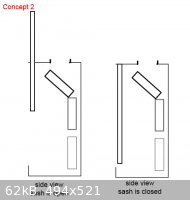
the second picture shows that it would just be one long glass pane. there would be a slot cut out of the ceiling of the fumehood cabinet towards the
front which allows the glass to slide up through this slot. this seems like it would work also but seems like it would be more unsightly when it's
open because the glass would be almost 4' tall, in fact my ceiling may not even be tall enough to support the cabinet plus an additional 4' for this
glass to go all the way up and the glass needs to go all the way up to fit tall pieces of glassware in it. so this may be do-able as a fallback, but
i'd love to figure out how to somehow get the glass to work as in concept 1, with railing on the side or something to pull it off.
any ideas that may help?
[Edited on 15-4-2009 by EmmisonJ]
|
|
|
Lambda-Eyde
National Hazard
Posts: 857
Registered: 20-11-2008
Location: Norway
Member Is Offline
Mood: Cleaved
|
|
Hey guys, it's me again!
So, I've finally done some real work on the lab. The framework for the bench and fumehood is done with, and I'm refurbishing my fire-proof chemicals
cabinet (read: removing rust and old paint). I've sent out some mails asking for prices on glue-laminated wood (got a factory a few tens of kms away
from home) and laboratory faucets (Chinese. I'm not driving there). Still waiting for answers, though. I'll make a thread on my construction progress
if anyone's interested (I love such threads myself!).
So, on to the fume hood. I'm about to put the ducting in place and I have a few questions about that. I'm going to use 100 mm (4") ducting, and there
are two reasons for that: The fan I'm using (posted on page 4) has 100 mm in- and outlets, and I have quite a large supply of 100 mm PVC plumbing
pipes and connectors lying around that I would like to put to a higher use.
Questions: Is 100 mm too small? Would there be any good in using 125 or 150 mm ducting even if the fan inlet is smaller? Also, I see that some of you
object to the use of plastic ducting because of the fire danger. Does this also apply to the heavy duty pipes (~5 mm walls IIRC) I have? I can
understand the concern with thin, flexible plastic ducting, but the problem should be non-existent with these pipes, right? When I need flexible
ducting (about 3 m), should I go for aluminium ducting (what about acids?) or some plastic ducting designed for workshop vacuum systems? I have quite
a few meters of the latter in my workshop, and it's quite tough. I don't know how it would stand up to long term solvent use, though.
And another problem: The vapors have to travel quite far from the hood to the fan, about two meters horizontally and three meters vertically. There
will be two bends where I will use flexible ducting to make the bends as smooth as possible to not upset the flow. There is really no alternative to
this route, as my parents would most likely kill me if I laid the ducting through our kitchen. Either that or they would die from some sudden
leak in the ducting while I had some freak accident involving large amounts of chlorine in the hood.
And hey, there's more! I have two alternatives as to how I should connect the hood to the ducting: At the top of the hood or at the top of the right
wall in the hood. I want to avoid the first one as it will introduce another, severe bend to the duct. Also, going for the second alternative allows
me to make the hood slightly taller (10-20 cm). I can't see any problems with the second alternative if I have the baffles depicted in the picture
integrated in the hood. Does any of the hood experts have any objections to this idea?
Here is a drawing of what my hood (hopefully) will look like:

The hood will be roughly 120 cm wide, I see that I forgot to include that in the drawing. The bench itself will be stainless steel (should I coat
it?), the walls and ceiling will be made of drywall (fireproof), painted and epoxy coated. The baffles I don't know yet, but I'll probably get some
aluminium plating and epoxy coat them as well if there's anything left after coating the walls.
The sash. I'm planning to have two layers: The inside glass and the outside plexiglass/acrylate/polycarbonate. Glass for chemical resistance (I'm not
playing with fluorine anyways) and plastic to make it more mechanically durable. I really don't like the feel of all-glass sashes anyways, it feels
like I can break it by lowering it too rapidly... Does anyone have any experience gluing large glass plates to large plastic plates? I bet it's not
easy to do without any air bubbles or other deformities.
I will have to come up with some ingenious idea for the lowering mechanism. I have a fume hood at school featuring a system of weights and strings
which I think I will copy (if I can make it work, that is). As you can see from the drawing, the sash is about 60 cm tall. In addition to that I will
have about 40 cm of glass integrated into the hood. The reason the sash itself is relatively short is because there's only about two meters from the
floor to the ceiling in my roof, so making it any longer would be pointless. I will leave about 10 cm of space for the airflow at the top of the hood.
I will also integrate a small sink and two gas outlets (vacuum and argon) in the hood if I can get a good deal from the faucets dealer I'm e-mailing.
Pretty nifty, huh? 
Phew, that's a huge wall of text I've made the last minutes. I hope you can bear with me and provide some feedback to my ideas. I'm counting on the
experts here! 
[Edited on 2-8-2010 by Lambda-Eyde]
|
|
|
Eclectic
National Hazard
Posts: 899
Registered: 14-11-2004
Member Is Offline
Mood: Obsessive
|
|
You may want to try cement tile backer board instead of drywall. It should be a lot more resistant to liquids and mechanical damage.
|
|
|
Magpie
lab constructor
Posts: 5939
Registered: 1-11-2003
Location: USA
Member Is Offline
Mood: Chemistry: the subtle science.
|
|
Your design incorporates a variable opening height of 20 to 60 cm. That's a 3 fold range of area. Therefore you can get a 3 fold range of face
velocity. That's why I promote a fixed opening area as in my hood design, previously provided. But in practice you will likely use only a limited
range of sash openings so the face velocity changes may not be an big issue. Use of a bunsen burner is an example where you don't want a lot of
change in face velocity.
Your blower flow is about 500cfm (units I can visualize). This should be good but you haven't provided the fan curve, ie, against what flow
resistance can the blower deliver this flow.
If the blower outlet is 100cm then it won't do much good to increase the duct size. You effectively would have a restricting orifice right at the
blower.
Overall, I think you are on the right track. But I would feel much more comfortable if I could see a fan curve.
Look into buying a window. This would save you a lot of trouble.
|
|
|
watson.fawkes
International Hazard
Posts: 2793
Registered: 16-8-2008
Member Is Offline
Mood: No Mood
|
|
Quote: Originally posted by Magpie  | | If the blower outlet is 100cm then it won't do much good to increase the duct size. You effectively would have a restricting orifice right at the
blower. |
A single restriction like that is just some constant static head loss. If the length of the duct is
long, that creates an additional head loss. It's perfectly fine to enlarge a duct for lower losses if it makes the system work better. Having said
that, unless the duct run gets on the long side, considerations other than friction loss will likely predominate. Take a look at this nomogram. The difference between 4" and 6" (100 mm and 150 mm, say) is about an order of magnitude. If the total loss is close to zero, this
difference may not matter. As always, it's a trade-off between cost of a heftier blower vs. cost of bigger ducts.
|
|
|
peach
Bon Vivant
Posts: 1428
Registered: 14-11-2008
Member Is Offline
Mood: No Mood
|
|
EmmisonJ, how's about sliding or hinging the sash horizontally?
[EDIT] CAN WE PLEASE MERGE AND STICKY THE FUME HOOD QUESTIONS? YOU GUYS WILL NAIL REPEAT QUESTIONS IN THE ASS, LET ALONE THOSE COMING FROM
NEW THREADS, AND YET THIS ONE IS HERE ALL THE TIME. IT'S DILUTING THE INFORMATION AND CLOGGING THE FORUM. STICKY IT. I'D ALSO RECOMMEND A STICKY FOR
VACUUM AND HOTPLATE QUESTIONS. [/all caps]
[Edited on 2-8-2010 by peach]
|
|
|
watson.fawkes
International Hazard
Posts: 2793
Registered: 16-8-2008
Member Is Offline
Mood: No Mood
|
|
| Quote: Originally posted by Lambda-Eyde | | Is 100 mm too small? [...] When I need flexible ducting (about 3 m), should I go for aluminium ducting (what about acids?) or some plastic ducting
designed for workshop vacuum systems? [...] The vapors have to travel quite far from the hood to the fan, about two meters horizontally and three
meters vertically. There will be two bends where I will use flexible ducting to make the bends as smooth as possible to not upset the flow.
|
As in my just-previous post, whether 100 mm is too small depends on your fan, the length of the run, and
your target flow rate.
The static loss from flexible corrugated pipe is quite large, something like an order of magnitude more than smooth pipe of the same diameter. Keep
the bends short and you'll be OK. Better yet, go get "wide sweep" fittings. With some care, large radius bends in PVC can be achieved with a hot air
gun and some fixtures and/or assistance. (I must admit I've never done it with anything as large as 100 mm.)
PVC should be just fine for a home lab as long as your not running solvent vapors up the chimney constantly. Some solvent will absorb into the
plastic. It will then desorb with fresh air. So if you use PVC pipe, purge the duct work when you're done with it each time.
Corrugated duct is typically made with vinyl plastic, which I'd worry about more, both because it's thin and it seems to be more subject to solvent
attack. As long as it's on the inlet side of the fan, though, any failure creates another inlet, not a new outlet for hood fumes. Nevertheless, if you
use it, keep it in sight so that you can inspect it.
A side outlet from the hood should be fine if you're using baffles. The baffles will do a lot to distribute the flow sideways across the width of the
hood.
|
|
|
Lambda-Eyde
National Hazard
Posts: 857
Registered: 20-11-2008
Location: Norway
Member Is Offline
Mood: Cleaved
|
|
| Quote: Originally posted by Magpie | | Your design incorporates a variable opening height of 20 to 60 cm. That's a 3 fold range of area. Therefore you can get a 3 fold range of face
velocity. That's why I promote a fixed opening area as in my hood design, previously provided. But in practice you will likely use only a limited
range of sash openings so the face velocity changes may not be an big issue. Use of a bunsen burner is an example where you don't want a lot of
change in face velocity. |
Thanks for the advice. I think I will go for my version as I like to have the opportunity to have a large shield between myself and the hood. I guess
it's a psychological thing.  I'll have it in the back of my head when using
burners. I'll have it in the back of my head when using
burners.
| Quote: Originally posted by Magpie |
Your blower flow is about 500cfm (units I can visualize). This should be good but you haven't provided the fan curve, ie, against what flow
resistance can the blower deliver this flow.
If the blower outlet is 100cm then it won't do much good to increase the duct size. You effectively would have a restricting orifice right at the
blower.
Overall, I think you are on the right track. But I would feel much more comfortable if I could see a fan curve.
Look into buying a window. This would save you a lot of trouble. |
I've been looking for a fan curve but it's proving to be difficult - I don't even know what the brand name is! However, I have the exact same blower
in my workshop and I may have the papers that came with it lying around somewhere. If I find it I might be able to find a fan curve. Would it be a
good idea to exchange the radial blade for some other configuration? Seems like I would need a blower capable of delivering an acceptable flow rate at
quite a high pressure drop - see below.
I have a few windows where I will scavenge the glass needed, if the sheets are large enough. Unfortunately I think they're under 120 cm wide. Cutting
such large sheets would also be a problem. I'll visit some glass suppliers to inquire about plexiglass and probably normal glass if my windows are too
small.
"Save me some trouble"? There's no such thing as trouble, only experience waiting to be earned.
| Quote: Originally posted by watson.fawkes | | A single restriction like that is just some constant static head loss. If the length of the duct is long, that creates an additional head loss. It's
perfectly fine to enlarge a duct for lower losses if it makes the system work better. Having said that, unless the duct run gets on the long side,
considerations other than friction loss will likely predominate. |
There's about 5 meters of ducting - would there be any point in swapping about two of those meters of 4" ducting with 5" or 6"? (100, 125, 150 mm)
Ducting isn't that expensive, I could probably even use all 5" or 6" ducting from the hood to the fan. But I would like to use some of the piping I
have laying around.
| Quote: Originally posted by watson.fawkes | | Take a look at this nomogram. The difference between 4" and 6" (100 mm and 150 mm, say) is about an order of magnitude. If the total loss is close to zero, this
difference may not matter. As always, it's a trade-off between cost of a heftier blower vs. cost of bigger ducts. |
Heck - a 500 cfm blower with 4" ducting is off the charts!  For about 5 meters of
ducting that corresponds to about 2" of H<sub>2</sub>O. And that doesn't account for the corrugated duct and the bends in the
system. That's no good. However, looking at the nomogram, using a 6" duct reduces the pressure drop to 0,33" of H<sub>2</sub>O,
quite a difference! But again, that doesn't account for the corrugated ducting and now the problem of the 4" inlet/outlet comes into play.
Does anyone dare to make a qualified guess as to how much it will interfere? For about 5 meters of
ducting that corresponds to about 2" of H<sub>2</sub>O. And that doesn't account for the corrugated duct and the bends in the
system. That's no good. However, looking at the nomogram, using a 6" duct reduces the pressure drop to 0,33" of H<sub>2</sub>O,
quite a difference! But again, that doesn't account for the corrugated ducting and now the problem of the 4" inlet/outlet comes into play.
Does anyone dare to make a qualified guess as to how much it will interfere?
| Quote: Originally posted by watson.fawkes |
The static loss from flexible corrugated pipe is quite large, something like an order of magnitude more than smooth pipe of the same diameter. Keep
the bends short and you'll be OK. Better yet, go get "wide sweep" fittings. With some care, large radius bends in PVC can be achieved with a hot air
gun and some fixtures and/or assistance. (I must admit I've never done it with anything as large as 100 mm.)
PVC should be just fine for a home lab as long as your not running solvent vapors up the chimney constantly. Some solvent will absorb into the
plastic. It will then desorb with fresh air. So if you use PVC pipe, purge the duct work when you're done with it each time.
Corrugated duct is typically made with vinyl plastic, which I'd worry about more, both because it's thin and it seems to be more subject to solvent
attack. As long as it's on the inlet side of the fan, though, any failure creates another inlet, not a new outlet for hood fumes. Nevertheless, if you
use it, keep it in sight so that you can inspect it.
A side outlet from the hood should be fine if you're using baffles. The baffles will do a lot to distribute the flow sideways across the width of the
hood. |
When you say "corrugated duct", I take it you're referring to aluminium ducting with plastic coating? Then plan is to use it only on the inlet side of
the fan as you say, I have thought about that problem. I'm considering using the heavy-duty flexible plastic ducting I mentioned earlier, but it seems
like I can only get 4". Looking at the monogram and some other fan curves I'm leaning more towards 5" or 6", whichever I can get. 2" of pressure drop
is quite a lot and will affect the flow severly.
What's a "wide sweep fitting"? I tried googling without much luck. Is it just a big bend instead of a sharp bend? I most likely won't buy it anyways,
as the prices for any adapters and fittings are ridiculous. For the bends I'll use the flexible ducting as it will allow me to make the bends exactly
as I want them at a fraction of the price.
Bending 100 mm PVC pipes with 5 mm walls seem like an ambitious project - I don't think I'll even try.  Also, the ducting has to go through two walls and a floor on the inlet side, so rigid pieces will be hard to implement
there. I want to use the 100 mm PVC pipes for the three meter vertical part, which is a straight line. Also, the ducting has to go through two walls and a floor on the inlet side, so rigid pieces will be hard to implement
there. I want to use the 100 mm PVC pipes for the three meter vertical part, which is a straight line.
Seems like I'm going to put the inlet on the side of the hood, with the proper baffles installed.
EmmisionJ: I'll look into those cement boards. I'd like to use plaster though, as I have some already plus it's dirt cheap. Adding enough epoxy solves
everything, right? 
Also, I second Peach's statement.
Thanks for the advice guys, it is greatly appreciated. I can't wait to start the real construction.
|
|
|
Magpie
lab constructor
Posts: 5939
Registered: 1-11-2003
Location: USA
Member Is Offline
Mood: Chemistry: the subtle science.
|
|
| Quote: Originally posted by Lambda-Eyde |
I think I will go for my version as I like to have the opportunity to have a large shield between myself and the hood. I guess it's a psychological
thing. |
I think you are misunderstanding me. Understanding the concept of a fixed open area with sliding sash seems to be difficult, and not
just for you. If I am mistaken, please accept my apology.
With my hood design I can have the sash all the way pulled down and still have the "fixed open area." With this design the face velocity never
changes, regardless of the position of the sash. My 450cfm blower always sees a constant air flow. That's what's removing the noxious gases, after
all. If you completely close your hood no air will flow and the noxious gases will just sit there.
Now when the sash is in the all-the-way down position, the open area above the sash does increase in area. But this is well above my
head so I'm not really worried about it. In between my face and the experimental apparatus is a double glazed window of tempered glass.
If you buy a 120cm wide x 150cm high window with only one sash (120cm wide x 75cm high, a special order) you will have a PVC frame ready to go. Now
if you are looking forward to constructing this dimensionally demanding cabinetry, with counter weights, then best wishes.
|
|
|
Lambda-Eyde
National Hazard
Posts: 857
Registered: 20-11-2008
Location: Norway
Member Is Offline
Mood: Cleaved
|
|
No, I understand you. It's my formulation in the above post that's too poor, sorry.
With my current design (which is not so easy to see in the drawing) There will be a permanent 10 cm opening at the top, and a 10 cm opening at the
bottom when the movable sash is pulled all the way down. Although it doesn't ensure a constant flow it ensures (hopefully) sufficient air
intake. When the sash is pulled all the way down the idea is to have full protection (glass) between me and the contents of the fume hood.
Does the benefits of the constant flow design outweigh the added security of an extra piece of glass?
|
|
|
watson.fawkes
International Hazard
Posts: 2793
Registered: 16-8-2008
Member Is Offline
Mood: No Mood
|
|
The
missing piece is the way of slowing down the flow when the sash is down. The term of art I've seen used most often is VAV = variable air volume. You
can get this with an adjustable speed fan, an inline damper, or an extra, switchable inlet in parallel with the hood.
A wide sweep bend is indeed just a big bend instead of a sharp one. If a sharp bend has a bend radius of 2x the duct radius, a wide sweep will be more
like 4x-6x. "Wide sweep" is the term of art in the USA, I'm certain that they're called something else elsewhere (not merely translated).
For more accurate computations of static loss, there are a number of loss calculators online than showed up with a Google search for "duct loss".
Before trying to use one, make a schematic of your system, annotated with dimensions.
The static loss from changing duct sizes depends on the geometry. A butt joint with no transition incurs a fair amount of loss (primarily from
turbulence). Taper transitions have far less loss. Again, the cost of fittings is a trade-off with the size of your fan.
|
|
|
Magpie
lab constructor
Posts: 5939
Registered: 1-11-2003
Location: USA
Member Is Offline
Mood: Chemistry: the subtle science.
|
|
I think you do understand "constant flow" design.
My typical "sash down" working height on the lower opening is ~22cm. This allows me to work with my gloved hands while still providing full face and
upper body protection by the sash.
So I think you are going to be good as long as your face velocity is appropriate (~ 0.3m/s) at about 22cm of lower opening height.
|
|
|
Lambda-Eyde
National Hazard
Posts: 857
Registered: 20-11-2008
Location: Norway
Member Is Offline
Mood: Cleaved
|
|
Watson: Thanks for the tip, I found a calculator and I've played with it quite a bit now. Quite some depressing results, though: depending on the
variables I get anything from 0,9" to 8".
Seems like five meters of 4" ducting is out of the question - and I absolutely have to find a fan curve.
|
|
|
peach
Bon Vivant
Posts: 1428
Registered: 14-11-2008
Member Is Offline
Mood: No Mood
|
|
I was going to say this as well, control the flow rate from the other end to make the sash open area more flexible.
I'm not sure, but I don't think a light dimmer will be too happy attached to a fan, due to light bulbs being resistive elements and the motor an
inductive / capacitive load.
[Edited on 3-8-2010 by peach]
|
|
|
cnidocyte
Hazard to Others
Posts: 214
Registered: 7-7-2010
Member Is Offline
Mood: No Mood
|
|
The cheapest sparkless fans I can find have a capacity of about 200cubic metres/hour (120 cubic feet per minute) )which isn't too bad but not the
best. Would putting 2 of these side by side double that capacity? If so would it be best to space between apart or install them right beside each
other?
|
|
|
Magpie
lab constructor
Posts: 5939
Registered: 1-11-2003
Location: USA
Member Is Offline
Mood: Chemistry: the subtle science.
|
|
I can't speak from experience about two fans in parallel, but I have read that it can produce an oscillatory effect, ie, a push-pull oscillation.
This is the result of the two fans not being in perfect balance with respect to each other and the resistance they "see." To mitigate this I would
place them in as nearly a symmetrical position as possible. Perhaps others know more about this.
The single most important condition for a successful synthesis is good mixing - Nicodem
|
|
|
peach
Bon Vivant
Posts: 1428
Registered: 14-11-2008
Member Is Offline
Mood: No Mood
|
|
This was a big deal in WW2 for the multiprop bombers. If the engines weren't in sync, they'd produce a pulsing noise like two strings on an instrument
nearly in tune with each other; which us brits could actually hear from miles across the channel using spiffing big concrete 'ears' with a guy sat in
the middle reading the paper, having a cup of tea.
It's also how a pulse jet works, resonant oscillation.
If they're both the same make of fan, I doubt it's going to be much of an issue. One will likely carry slightly more load than the other, but not a
lot else.
I also doubt your fan needs to be truly sparkless in the first place. A centrifugal is already pretty good in that the motor is separate from the
airflow, unlike a lot of axials.
Get that scrubber on thar though! Right against the hood.
I'll be posting some photos in the 'tour my lab' thread demonstrating what things like hydrogen chloride gas do to 'stainless'. It's pretty, but not
necessarily what you want to happen, and it happens overnight.
Edit: If you check out the wiki article on ground glass, you can have a sneak preview of the effects and you'll see marmalade has made another
internet appearance, along with some clips that have come into contact with trace quantities of hydrogen chloride.
Scroll to keck clips
[Edited on 23-8-2010 by peach]
|
|
|
cnidocyte
Hazard to Others
Posts: 214
Registered: 7-7-2010
Member Is Offline
Mood: No Mood
|
|
Bilge blowers can be bought for around $25 and since they're designed for extracting petrol fumes, they are completely sparkless. They have decent
capacity too. The 3 inch fans have a capacity of around 200m^3/h but I saw a site selling 4 inchers with a capacity of 350m^3/h. Not bad at all for
$35. Bilge blowers are inline fans, centrifugial fans would be better for placing on the roof of a hood but in my case, its far more practical to
mount the fan on one of the walls of the hood.
|
|
|
Gearhead_Shem_Tov
Hazard to Others
Posts: 167
Registered: 22-8-2008
Location: Adelaide, South Australia
Member Is Offline
Mood: No Mood
|
|
Formply for bench and/or fume hood?
I'm looking at getting a sheet of formply (a.k.a. hard face) plywood to build my lab bench & fume hood (and maybe a chemical storage cabinet).
Formply is used for making concrete forms and is exterior-grade plywood with a phenolic coating on the outer hardwood plies. I reckon since phenolic
has pretty good chemical resistance properties that it should work well, at least for a bench top. The phenolic layer is quite thin, less than half a
millimetre, so I would probably put ceramic tiles down inside the fume hood to take the brunt of any spillage.
I can pick up a brand new 1200 x 2400 x 17 sheet locally for $64AU or a surplus "second" sheet for about $45AU.
Has anyone tried this stuff? It's quite a bit more expensive than cement board, but heaps stronger.
-Bobby
|
|
|
spong
Hazard to Others
Posts: 128
Registered: 28-5-2009
Location: Chatham
Member Is Offline
Mood: No Mood
|
|
I was looking in the tip shop today for an old fridge to use the compressor from and I found this and thought it could be modified a little to make a
fumehood, I then realized it was a fridge and has a compressor in it
Does it look like it could be relatively easily modified to turn into a fumehood? I like the fact that it's stainless steel and pretty much airtight
(provided I put the doors back on and fix a few broken seals) and has the glass on the front. It's $15 and they don't sell ordinary fridges there so
I'll be buying it either way.


Here's the compressor:

|
|
|
cnidocyte
Hazard to Others
Posts: 214
Registered: 7-7-2010
Member Is Offline
Mood: No Mood
|
|
^^ My god you got that for $15? There are probably all sorts of alternative uses for that fridge. Whats a tip shop? I can't really say if that would
make a good fume hood. I'd try and cut a rectangle out with a glass cutter, then attach a plexiglass flap.
|
|
|
spong
Hazard to Others
Posts: 128
Registered: 28-5-2009
Location: Chatham
Member Is Offline
Mood: No Mood
|
|
Yeah its a shop at the tip (dump) where they collect anything of use and sell it. It's great, I got 2 hotplates for $2 they have some pretty
interesting stuff there at times.
|
|
|
cnidocyte
Hazard to Others
Posts: 214
Registered: 7-7-2010
Member Is Offline
Mood: No Mood
|
|
I tested my fumehood out today for the first time, I gave it a blast of the fire extinguisher but unfortunately it only extracted about 80% of the
dust cloud. Reducing the area of the opening should take care of that though. Smaller opening, greater face velocity. Not gonna have much space to get
my arms in there though.
|
|
|
entropy51
Gone, but not forgotten
Posts: 1612
Registered: 30-5-2009
Member Is Offline
Mood: Fissile
|
|
A blast from a fire extinguisher is not a very realistic simulation of chemistry, or at least non-runaway chemistry.
Use a few pieces of dry ice in beakers and flasks of water to generate vapor clouds for testing the exhaust. By adding more small pieces of dry ice
you can increase the rate of cloud formation and see at what point some of it begins to escape the hood.
|
|
|
| Pages:
1
..
3
4
5
6
7
8 |


