| Pages:
1
2
3 |
dann2
International Hazard

Posts: 1523
Registered: 31-1-2007
Member Is Offline
Mood: No Mood
|
|
Hello,
Could get no satisfaction from an inductor made from a gapped MOT. The inductance that is obtained is just too small. Tried a large transformer but it
is not worth the bother (IMO) unless you happen to have a large transformer core to hand.
See attached file for some observations regarding an MOT Chlorate cell supply.
Dann2
Attachment: MOT supply waveforms.mht (178kB)
This file has been downloaded 20430 times
|
|
|
dann2
International Hazard
Posts: 1523
Registered: 31-1-2007
Member Is Offline
Mood: No Mood
|
|
Hello,
During my travels on the interwebs I came accross the following (real mans) welder. It DID make me laugh. I actually though it was a joke but it is
not. The transformer tied together with cord takes the biscuit. Then there's the welding goggles.................
http://www.jalopyjournal.com/forum/showthread.php?p=3385547
Can any helpful soul explain to me how a constant current transformer works. I am talking about one of the type that has two coils on the core. One
coil is stationary and the other is allowed to move (aided with a counter weight) so that the current is regulated in a very exacting manner.
There is a doc. attached.
It does not make sense to me. I always thought that it did not matter too much where on the core you put the second winding (within reason). According
to the constant current transformer stuff if you move the coils some inches towards and away from each other it makes a hugh difference and allows
very precise current regulation????????
The core seems to look like an ordinary core but it is a bit longer to allow for movement of the coils.?
See here page 98
US 2807787 is another example.
Dann2
Attachment: CCR BROCHURE.pdf (653kB)
This file has been downloaded 782 times
|
|
|
watson.fawkes
International Hazard
Posts: 2793
Registered: 16-8-2008
Member Is Offline
Mood: No Mood
|
|
Quote: Originally posted by dann2  | | I always thought that it did not matter too much where on the core you put the second winding (within reason). |
Often yes, but really no, as you've found out from reading. The magic label in the diagram you referenced is the one labeled
"leakage flux". This is magnetic field flux that is made by the primary but not picked up by the secondary. Controlling the leakage flux is the way
that the device produces constant current.
|
|
|
dann2
International Hazard
Posts: 1523
Registered: 31-1-2007
Member Is Offline
Mood: No Mood
|
|
The core looks reasonable well dimensioned. It is not very thin or very long (it is somewhat longer that other transformers though), does not have any
air gaps or shunts to incourage leakage flux. I simply cannot understand how simply spacing the coils a bit turns the thing from what we normally get
(a 'normal' transformer) into something that gives out a constant current.
Anyhow, I guess it does. Some of those text books need rewriting when they show a diagram of a core with coils on it and state "It makes no
difference where you place the coils on the Iron core as all (or almost all) the flux is contained within the Iron core" etc etc.
No doubt you would expect some differences to occur as the coils are moved closer together but not the hugh difference that these constant current
transformers are giving, simple my moving the coils some inches.
Let me see: Two MOT's cut open, and two 'E's' placed together (hopefully no air gap)with one mains coil left on one of them. A few turns for the
secondary and make the secondary bobbin winding in such a way that it can be slid up and down a bit for giving different currents. Can't see it
working but I guess it will?????
Dann2
|
|
|
watson.fawkes
International Hazard
Posts: 2793
Registered: 16-8-2008
Member Is Offline
Mood: No Mood
|
|
| Quote: Originally posted by dann2 | | "It makes no difference where you place the coils on the Iron core as all (or almost all) the flux is contained within the Iron core"
|
Are you certain that the center post (the one that the secondary moves on) is made of iron?
Look up "magnetic permeability", and then look up its value for iron. The answer won't make sense unless you understand the concept and know the value
for iron.
|
|
|
dann2
International Hazard
Posts: 1523
Registered: 31-1-2007
Member Is Offline
Mood: No Mood
|
|
Hello,
I am not certain that the core if made of Iron.
I have presumed (perhaps I am presuming wrong) that the core is made similar to other power transformer cores (the usual laminated Silicon steel). The
only thing I can see different with cores for the constant current transformers it the fact that the core is a bit longer to allow (I think?) for
movement of the secondary.
(This extra length will add very little reluctance to the core compared to a shorter ('normal' shorter length for more conventional power transformer)
core of similar cross section if the core is made from Si Steel.)
____________
Edit:
Hipersil steel is used in the CC Transformer in the brochure above. It's a trade name for High Permeability Silicon Steel. Would presume the whole
core is made from it.
___________
The whole concept beats me. I cannot find much any info. on what the cores are actually made from. There appears to be no magnetic shunts or air gaps
in the core, just the moving secondary on Iron core. Will have another look for more info.
Dann2
[Edited on 29-6-2009 by dann2]
|
|
|
12AX7
Post Harlot
Posts: 4803
Registered: 8-3-2005
Location: oscillating
Member Is Offline
Mood: informative
|
|
If the secondary remains in a constant position, there will be a certain amount of leakage flux around it, due to the gap between the primary and
secondary. In current-limited transformers, this is often accentuated with a high permeability material in the gap (yielding a smaller package),
i.e., magnetic shunts. Air works the same way, it just takes a lot more of it, hence the much longer travel necessary.
The other factor is the active control loop produced by allowing the secondary to move. This turns the characteristic from ohmic to nonohmic (over
the long run), controlling current much more precisely. (Notice that, in the short term, the heavy secondary will not have time to move and fairly
large peak currents can be drawn.)
Tim
|
|
|
merrlin
Hazard to Others
Posts: 110
Registered: 3-4-2009
Member Is Offline
Mood: No Mood
|
|
| Quote: Originally posted by dann2 |
The core looks reasonable well dimensioned. It is not very thin or very long (it is somewhat longer that other transformers though), does not have any
air gaps or shunts to incourage leakage flux.
Dann2 |
The gap between the core and the secondary that allows the secondary to float will increase leakage inductance. Since you seem to be putting a fair
amount of effort into your project, I suggest that you download the student version of Ansoft's Maxwell 2D E-M modeling software and review the
examples before building your own models.
http://www.ansoft.com/maxwellsv/
|
|
|
dann2
International Hazard
Posts: 1523
Registered: 31-1-2007
Member Is Offline
Mood: No Mood
|
|
Hello,
Thanks for replys and I will download and see can I use that software.
I guess the following is where the design of the CC transformer differs from a transformer designed for good Voltage regulation.(deliberately put
into the design of this type of transformer as suggested by yourselves to obtain leakage flux):
Large spacing between the inner side of the windings and the middle core leg +
The core is longer than a transformer with good Voltage regulation of similar VA +
The coils being spaced apart from each other on this longer middle leg
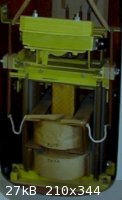
I have attached a picture from the brochure for the CC Transformer.
It would appear from looking at it that the coils look to have alot of space between their innner (rectangular) winding layer and the core. There
appears to be a spacer (the dirty yellow coloured thing that looks like a big ice cream wafer!) along the core middle leg to fill up the space? Just
guessing from looking at it.
I have tried to give the MOT I was working with a more constant current nature by adding more magnetic shunting. Also added an air gap in the core
(along with the shunts accross the core between coils). They all help but you still do not get a 'real' constant currrent transformer, just a
transformer with less and less Voltage regulation and more and more current regulation. I would like a transformer with a more regulated (fixed)
current supply value. I do not think this is possible with simple shunts and/or air gaps unless you have it designed to give out quite a high Voltage
(say 50 Volts) when there is no load attached. When this (50V with no load) transformer is then loaded so that output Voltage is dropped way down from
50 to say 8 or less Volts then you will get a fairly well defined programmed current. ie. a large difference between open circuit Voltage and (roughly
6 to 9 Volts) the working Voltage makes. There is no space in the MOT for the number of windings to give me an open circuit Voltage of (say) 50
Volts.
Will try to combine two MOT "E" pieces (of similar size) to give a long core. Primary will be one MOT primary (which unfortunately will be tight on
the core which I do not want) + secondary on a moving bobbin. May work / may not, like a pipe dream.
|
|
|
12AX7
Post Harlot
Posts: 4803
Registered: 8-3-2005
Location: oscillating
Member Is Offline
Mood: informative
|
|
| Quote: Originally posted by dann2 | | They all help but you still do not get a 'real' constant currrent transformer, just a transformer with less and less Voltage regulation and more and
more current regulation. |
That is exactly how a current source can be defined. An ideal current source's Thevenin equivalent has Vs/Rs = Iout and Vs, Rs --> infinity. A
real-life approximation is not only supposed to have a high O/C voltage, it is required to! Notice this CC transformer will likewise have a high OCV.
Tim
[Edited on 6-30-2009 by 12AX7]
|
|
|
watson.fawkes
International Hazard
Posts: 2793
Registered: 16-8-2008
Member Is Offline
Mood: No Mood
|
|
The vertical member in the brochure looks like phenolic to me, not iron. The difference in permeability is the difference between "regulates" and
"does not regulate".
|
|
|
dann2
International Hazard
Posts: 1523
Registered: 31-1-2007
Member Is Offline
Mood: No Mood
|
|
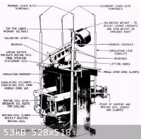
Another picture of CC transformer below from
http://www.tpub.com/celec/5.htm
The diagram suggests the middle leg is part of the 'core', ie. made of Iron.
The permeability of Phenolic would be far too low IMO. The input coil would look like a short circuit and bugger all coupling to secondary would
occur.
Dann2
[Edited on 1-7-2009 by dann2]
|
|
|
watson.fawkes
International Hazard
Posts: 2793
Registered: 16-8-2008
Member Is Offline
Mood: No Mood
|
|
| Quote: Originally posted by dann2 | The diagram suggests the middle leg is part of the 'core', ie. made of Iron.
The permeability of Phenolic would be far too low IMO. The input coil would look like a short circuit and bugger all coupling to secondary would
occur. |
Coils have inductance even in complete absence of a core, so-called "air core" coils. There are also
air-core transformers, albeit specialty items. A core changes the inductance of a coil by a factor of its permeability, but this doesn't eliminate the
inductance. Transformer coupling is about the ratio between mutual inductance and total inductance. And a core doesn't change the DC resistance at
all.
This whole device hinges on an interplay between geometry of the device and permeability of the material. My intuition about the magnitude of
permeability indicates that you're not going to use a maximally-permeable material, but I might be wrong about that. The reason you use a core is to
minimize leakage inductance, which increases the linearity of the transformer. But a constant-current source is as non-linear an element as it gets!
If you're trying to regulate over a large range, using an iron core may not be what you want. But at this point I'll simply second the recommendation
to run a simulation.
|
|
|
dann2
International Hazard
Posts: 1523
Registered: 31-1-2007
Member Is Offline
Mood: No Mood
|
|
Hello,
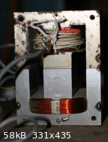
I put together the device in the picture. It is two 'E' MOT pieces on top of one another (laminations not interlayered, there are three gaps). It
does not have alot of range. As I start to add more air gap, the range goes up a bit. Maximum air gap size I have used in 0.8mm. When I say air gap I
actually mean three air gaps, one in each leg (middle core and two outside legs). It would be best if I only gapped the middle core (correct?). I will
have another go at the thing with the middle core (damm near) removed. I can obtain the two 'I' pieces and put them into the two outside legs. I have
a choice of three thicknesses depending on what way I put the 'I' pieces between the top and bottom 'E's. This will make the overall core much longer
with a hugh gap in the middle (core) leg. A picture will explain better next time.
The set up pictured gives a noticable force between the primary (bottom) and home wound secondary at 15 amps and above. The secondary is lifted to the
top at 25 five amps or even less. The vibration (noisy) core helps to stop the (not very precisionly built) secondary bobbin from jaming. The
'control' is yours truly moving the coil at this stage.
I cannot see this thing being something anyone would want to build as you will need quite a sweetly built sliding bobben/weights/pivots etc, system.
There is another picture of a CC Transformer here page 352.
Hard to figure out what the picture is saying about the core type/shape, or if it is trying to say anything at all.
Thanks for replys.
Dann2
|
|
|
watson.fawkes
International Hazard
Posts: 2793
Registered: 16-8-2008
Member Is Offline
Mood: No Mood
|
|
If you'd like to modify your transformer for greater range, take out some of the iron in the center section. If the layers are stuck together with
some resin (as typical), you should be able to notch the sheet metal, get a tool between layers, and peel off the layer. There's no need for a reduced
core in the center of the fixed primary; the rest of the center section is what to reduce.
|
|
|
12AX7
Post Harlot
Posts: 4803
Registered: 8-3-2005
Location: oscillating
Member Is Offline
Mood: informative
|
|
Mind that adding air gap will increase magnetizing current even further -- and it's usually over the edge already.
Tim
|
|
|
Vegemeister
Harmless
Posts: 4
Registered: 30-11-2008
Member Is Offline
Mood: No Mood
|
|
I think y'all are greatly overcomplicating matters. The cell couldn't care less about regulation. As long as it gets DC, it's happy. Heck, if
you're using MMO on Ti for both the anode and the cathode you can probably give the cell AC and it wont notice.
I have much more MMO plated expanded Ti than I have bare Ti or welding equipment, so I use an MMO cathode and make mechanical connnections above the
surface of the electrolyte and protect them with hot melt glue. I have not yet implemented this AC plan, but I hope it might do something about the
carbonate collecting on the cathode. Try it at your own risk.
You really don't need to worry about constant current. If it concerns you, put two splices 1 foot apart into a lengh of 10 AWG copper (preferably
solid core) and put it in series with the cell. the potential between the splices in millivolts is a reasonable approximation of the current in
amperes. Do a trapezoid approximation of the current*time integral if you want to calculate your current efficiency.
Your main concern should probably be reducing losses in the transformer and resistive losses from unnecessary overvoltage. Microwave oven
transformers are, by design, very non-ideal transformers. The plate current in domestic oven magnetrons is regulated in a manner which depends on the
transformer being operated well into saturation. Also, copper and silicon steel are at the expense of the oven manufacturer while electricity is at
the expense of the consumer. These transformers, while accessible, are quite under-engineered. My recommendations are as follows:
1. Knock out the shunts.
2. Wind some extra turns on the primary (make sure you put them in phase with the rest of the primary). Or, put two transformers in series, both
windings.
3. If you want to go DC, use a center-tap full wave rectifier, not a bridge, and use schottky diodes. This means one small schottky drop in between
the transformer and the cell instead of two big pn drops. With the voltages we're running, those diode drops contribute significantly to
inefficiency. A center tap is easily made by using a bifilar winding.
If you use two transformers in series, DO NOT use the point in between the two cores as the center tap. If you do this, each transformer core will
only see DC. Instead, make a bifilar winding that includes both cores.
4. You should probably not use a filter capacitor. This forces the transformer to deliver large pulses of current when the output voltage exceeds the
bus capacitor voltage. Transformers do not like this, and the problem gets worse the bigger you make the capacitor. Without a cap, the tranny still
sees pulses as the output voltage exceeds the cell voltage, but a capacitor is worse. Furthermore, getting ripple under control at tens of amps and
60 Hz requires a very expensive capacitor. The cell really doesn't mind.
5. Adjust your tuns ratio such that the current (once the cell temperature has equilibrated) is reasonable for your electrode surface area.
|
|
|
dann2
International Hazard
Posts: 1523
Registered: 31-1-2007
Member Is Offline
Mood: No Mood
|
|
Greetings Cabbage head,
One step in the MOT conversion that you left out is getting rid of the secondary winding. I find it is inclined to take up too much room if you leave
it there 
How do you bifilar wind the two transformers to get the center tap in such a way that you will have no 'transformer seeing DC only, problems'.
I set up the two MOT cores as the last picture above shows and tried it with no air gap, 0.4mm gaps and 0.8mm gaps. I only put half the normal input
Voltage into the MOT using a Variac.
I used a large Graphite Anode in a Chlorate cell and moved the Anode in and out to simulate the Voltage variation accross a Chlorate cell. I only
varied the Voltage by (approx.) 0.85 Volts.
To make a long story longer the best results were obtained when there was a 0.8mm gap in the transformer (in all three legs).
With the moving coil furthest away from the primary:
The current when Anode was in the cell fully was at 15 amps, 3.25 Volts accross cell.
Then the Anode was moved out, so that Voltage accross cell was now 4.1 Volts and current into cell had dropped to 11.1 amps (simulate a rising Voltage
accross cell).
The coil was now moved untill it was at it's closest to the primary and the current went up to 17.5 amps with 4.63 Volts accross cell.
So I suppose there is scope to use a contraption like this to controll the current into a Chlorate cell and keep it constant if you added a smooth
mechanism to allow the output coil to move but it would simply not be worth the bother. The Voltage variation simulated was very small anyways and it
would not be representative of the wider Voltage variation you will get with a Chlorate cell when temperature, concentrations etc change.
Will try larger gaps in middle leg with no gaps in outer legs if I get the inclination.
Cheers,
Dann2
[Edited on 20-7-2009 by dann2]
|
|
|
WizardX
Hazard to Self
Posts: 61
Registered: 11-8-2005
Location: wizardx.4shared.com
Member Is Offline
Mood: wizardx.suddenlaunch3.com
|
|
This power supply is great for powering all kinds of electronic projects. It produces a well filtered, variable 1.2-30 volts at 5 amps.
http://www.aaroncake.net/Circuits/supply.asp
Albert Einstein - \"Great ideas often receive violent opposition from mediocre minds.\"
|
|
|
dann2
International Hazard
Posts: 1523
Registered: 31-1-2007
Member Is Offline
Mood: No Mood
|
|
Hello,
I hate being a party pooper BUT that supply will not supply five amps and avoid meltdown of the LM338.
It will supply 5 amps (guaranteed) when the Voltage between output and input is 10 Volts or less with the case at 25°C (large heatsink). If the
Voltage between input and output is 30 Volts it will only supply one amp. It's all about power dissipation in the device and how much heat is
generated. See the data sheet page three forth row of the table up from the bottom. Or the graph just below table on left (page three).
Its a mistake made quite a lot to assum that when a device is declared to have a (say) 5 amp capability that it can output 5 amps under all
input/output Voltage conditions. It will go on fire if you put 30 volts accross the device from input to output and draw 5 amps out of it. (This
device wont burn up because its internal circuitary will limit the current (it will stop working as you would like).
30 (Volts) * 5 amps = 150 Watts = device on fire!!!!!!
http://www.datasheetcatalog.org/datasheet/stmicroelectronics...
Dann2
|
|
|
dann2
International Hazard
Posts: 1523
Registered: 31-1-2007
Member Is Offline
Mood: No Mood
|
|
CC Add-on
Hello,
Got around to putting together a constant current add-on for a computer power supply. Works OK. The maximum amount of current the thing can put out
will depend on what Voltage you will ask the IFRZ44N to drop but using the 5 Volt output of the PC supply and connecting to a Chlorate cell it will be
OK for a modest 10 Amps. The IFRZ44N is heatsinked using a microprocessor heatsink with a small fan on the back.
R1 consists of 50 cm of 1mm Copper wire. A 741 op-amp will not do this job as it will latch up to the power rails. I used a CA3140E.
Current regulation is good when tested with an 0.3 Ohm resistor as load. When 10 AMps out was set it also give 10 Amps when the resistor was short
circuited.
The whole thinn should fit inside the PC Power supply case.
Dann2
Attachment: cc.zip (83kB)
This file has been downloaded 506 times
|
|
|
12AX7
Post Harlot
Posts: 4803
Registered: 8-3-2005
Location: oscillating
Member Is Offline
Mood: informative
|
|
The LM358 includes the ground rail, and even this lowly op-amp has better performance than a damn 741. CA3140 looks like a good choice, although like
all MOS amps it's quite noisy.
Copper is a very poor choice for shunt because it has a massive tempco. Nichrome is much better, and better still is nichrome bonded to a base,
especially a base you can heatsink. Aluminum body resistors are fairly expensive, but do a good job (and they're usually 1% too).
If you'd like more current handling, you can of course connect any number of these circuits in parallel. You might consider using larger transistors,
as the TO-220 package is really only good for 50W. TO-247 is good for 100W. A couple hundred watts is a lot to dissipate and you might also consider
a circulating water supply for them -- saves on expensive heatsinks, and a bucket of water dissipates heat surprisingly well.
Tim
|
|
|
Swede
Hazard to Others
Posts: 491
Registered: 4-9-2008
Member Is Offline
Mood: No Mood
|
|
I'm a bit late into this thread, but for rewinding transformers and cabling cells, there are two outstanding sources of excellent heavy Cu wire that
is both flexible, and in one case, has a nice, thin PTFE insulation. The first is welding cable, traditionally used to ground the work. Most good
shops have big spools of #6 through #0 stranded copper that is limp as a noodle, very easy to wind, although the insulation jacket is fairly thick.
Still, it is a MUCH better bet than household #2 Cu cable, which damned near requires he-man muscles to manipulate.
The other alternative is scrapped or surplus aircraft cable. They are almost always insulated with a PFA or sometime kapton sheathe that is thin and
allows for a higher number of turns. One last option is to strip the welding cable of it's heavy rubber jacket, and insulate with a spiral wrap of
Kapton tape.
I agree that a decent power supply is probably the most challenging thing a new experimenter must obtain. 20 amps or less is easy. 50 to 100 amps
into 25+ liters, much harder. Having constant current is a joy if you are into calculating efficiencies, and experimenting with cell parameters to
see how they affect CE.
One last thought - 500W to 1KW 5V fixed supplies are a dime a dozen on eBay, and can be found for $25 to $50. The vast majority have a trimmer pot
that allows voltage adjustment through a narrow range. Most that I've seen allow 4V to 6V, a nice range for a chlorate cell. I've been tempted to
export that trimmer into an external 10 turn pot, or at least a better potentiometer for everyday use, although I'd probably derate the supply by 20%
or more when wanking with the voltage like that.
|
|
|
dann2
International Hazard
Posts: 1523
Registered: 31-1-2007
Member Is Offline
Mood: No Mood
|
|
Hello,
What do you mean by 'The LM358 includes the ground rail' ?
I actually did not choose the CA3140, it was what I had to hand (after messing with the 741 for some hours). Lucky guess I guess.
I thought the TempCo would matter damm all with this circuit as we want a relatively crude current out (not precision anyways). Setting the current at
10 Amps and holding a lit match under the Copper coil (0.01 resistor) the current droped to 7 Amps with just some heating. I then heated the resistor
with a hairdryer, which would be a more realistic simulation of operating conditioins and the current dropped to 9 Amps. Will have to get out the
piggy bank and purchase some Nichrome. I have 28 SWG Nichrome but it would take too many strands or/and the resistor would be too short and difficult
to connect when constructed.
There is a wire resistance table here:
http://www.kayelaby.npl.co.uk/general_physics/2_6/2_6_2.html
I am tempted to try a small Graphite rod. TempCo is low (and negative), metals are +).
http://library.thinkquest.org/10784/tempcoeffs_resistivity.h...
Whats ya's think?
If you have a physically small meter (say 1mA FSD) and you want it to read 10 Volts exactly when your system is OK, it can be difficult to read the
small meter. Is there any way to connect the same meter in such a way that it would read from 8 Volts (zero on meter) to 12 Volts (FSD).
This would greatly increase the resolution of small meters in the region where you want it.
A Zener in series with a smaller resistor (than you would use if there was no Zener) in series with the meter sounds like it would do the job. A small
meter in the PC power supply case would be great.
About those hugh 4 to 6 Volt power supplies. I often though that you could turn them into a constant current supply by connecting a stepper motor to
the adjustment pot and sensing the current and moving the stepper accordingly. This would require a microcontroller. I am messing aroung with PIC's at
the moment. It would be a good project to take on and more importantly a GREAT CAUSE   
Don't hold you breath for the final circuit draft..........
Cheers,
Dann2
[Edited on 7-10-2009 by dann2]
|
|
|
12AX7
Post Harlot
Posts: 4803
Registered: 8-3-2005
Location: oscillating
Member Is Offline
Mood: informative
|
|
The input common mode range. 741 and most FET amps (LF411, TL072, etc.) go from 2V above the negative rail to 2V below the positive rail, both input
and output. Some amps are specified for operation including one or the other rail. The LM358 is good for -0.3V input. Most op-amps, when taken out
of their common mode range, do weird things, like invert the output, or slam to +V.
Might work, but resistance varies with pressure (maybe unless you have a very dense piece of graphite). And you need a fairly thin piece for the
current you're at. And you need to make contacts -- which isn't the hardest part, as you can plate copper onto graphite very nicely.
| Quote: | | If you have a physically small meter (say 1mA FSD) and you want it to read 10 Volts exactly when your system is OK, it can be difficult to read the
small meter. Is there any way to connect the same meter in such a way that it would read from 8 Volts (zero on meter) to 12 Volts (FSD).
|
Get a better meter. Or subtract 8V from it so it reads 0 to 4V. (To cover the negative range, a series protection diode would be wise.)
| Quote: | | About those hugh 4 to 6 Volt power supplies. I often though that you could turn them into a constant current supply by connecting a stepper motor to
the adjustment pot and sensing the current and moving the stepper accordingly. |
Wow, that's a terrible waste. I bet you an entire supply that they are voltage controlled. The pot changes either the feedback or reference voltage.
Simply replace it with a control voltage input, or an error amp in the former case, and there you go.
Tim
|
|
|
| Pages:
1
2
3 |


