dann2
International Hazard

Posts: 1523
Registered: 31-1-2007
Member Is Offline
Mood: No Mood
|
|
Brush shorting VARIAC?
Hello Folks,
Some time ago there was a discussion on 'Why does the brush on a Variac not short out the two windings it sits on and cause a heavy current to flow'
Tim suggested that the brush contact must have a high resistance to stop this happening.
This page explained it fairly good. It would seem that the carbon brush does not conduct in all direction equally well! (You learn something new
every day).
Hope noone is going to tell me they have a Variac with a Copper brush..................
Variable AC --------------------> Variac (you can never have enough of them you know)
Dann2
|
|
|
hissingnoise
International Hazard
Posts: 3940
Registered: 26-12-2002
Member Is Offline
Mood: Pulverulescent!
|
|
I've always assumed that the difference in voltage between individual windings (~1v) is too small to cause a problem.
Brushes on a motor serve the same basic function and are usually in contact with more than one conductor at a time. . .
|
|
|
jimwig
Hazard to Others
Posts: 215
Registered: 17-5-2003
Location: the sunny south
Member Is Offline
Mood: No Mood
|
|
thin long brushes
my variacs had thin long brushes that would not contact more than say two windings at once.
craZy jiM wGGns
--packrat, professional bum. -- once just tired
now REtired.
|
|
|
merrlin
Hazard to Others
Posts: 110
Registered: 3-4-2009
Member Is Offline
Mood: No Mood
|
|
Low interwinding voltage, contact resistance, and the cited anisotropy of polycrystalline graphite all contribute to limiting of the interwinding
current. If it were simply a function of the graphite anisotropy, I would expect that pyrolytic graphite would be used, since the anisotropy of
pyrolytic graphite is orders of magnitude greater than that of polycrystalline graphite.
|
|
|
12AX7
Post Harlot
Posts: 4803
Registered: 8-3-2005
Location: oscillating
Member Is Offline
Mood: informative
|
|
Copper brush? I may just do that, the contact on mine is terrible. Sandpaper probably wouldn't hurt either...
TIm
|
|
|
watson.fawkes
International Hazard
Posts: 2793
Registered: 16-8-2008
Member Is Offline
Mood: No Mood
|
|
I've read the article referenced, twice now, just to make sure, and I think the explanation about the use of graphite is wrong. I don't mean
physically wrong; I'm not question the stated facts about graphite. I'm disputing their significance. I don't think it has much anything to do with
resistance or anything like it, but rather with its material properties that give it greater durability.
I'll start with inductive kick. Suppose a steady current is flowing through an autotransformer and suddenly two adjacent turns are shorted out. This
is equivalent to closing a switch in parallel with an inductor consisting of a single coil of the transformer. Current starts flowing through the
switch and stops flowing through the coil. There's stored energy in the coil that discharges through the switch. That's the inductive kick, but a
slightly different kind than the typical one where the switch is in series and opens. The total energy in the coil is 1/2 LI^2.
What's the inductance of that single coil? This requires a bit of guesswork (as I have neither an autotransformer nor an inductance meter handy), but
I'll make an overestimate and assume that it's 2 mH. You can go to Wikipedia on Inductors and make your own estimate. (I assumed a characteristic length of 10 cm and relative permeability of 10^4 and modest fudge factor).
Suppose we have a 10 A current flowing (a transformer rated 1 kVA in 120 V mains at about 80% capacity). The total energy in the present example is
thus 0.1 J. That's not a lot of energy. Swing the knob and short-out 100 turns in a second and you've got an average power dissipation for that second
of 10 W.
Now if the switch has very low resistance, the bulk of that energy is going to flow at the moment of contact. You're going to get instantaneous
heating at the point of contact. This is likely the problem with copper contacts. Microscopic surface roughness will lead to point heating and
spalling. So it's not that a copper contact won't work, but it will have lower service life. Carbon, with higher resistance, has lower point heating.
As a refractory material, its resistance to heating is much higher. And its oxide is gaseous, unlike copper oxide, which is an insulator.
If you're building or refurbishing a variac and don't want to use carbon, I imagine that a nickel contact point would perform adequately, with less
spalling. Small piece of nickel alloy can be scavenged from dead battery packs, whose contact tabs tend to be made from it.
|
|
|
jimwig
Hazard to Others
Posts: 215
Registered: 17-5-2003
Location: the sunny south
Member Is Offline
Mood: No Mood
|
|
real world seems to trump
so say someone uses his or her variac -as in slow rotation of the contact across the windings........sort of like common sense would dictate.........
and unless a destructive test is in order .... what is there worry to about...... the real world seems to trump in this case.......??????!!!!!!!
just as aside what about using silver brush contact..... get them from large main breakers innards. three per unit......????
[Edited on 12-6-2009 by jimwig]
craZy jiM wGGns
--packrat, professional bum. -- once just tired
now REtired.
|
|
|
12AX7
Post Harlot
Posts: 4803
Registered: 8-3-2005
Location: oscillating
Member Is Offline
Mood: informative
|
|
Nah, you're looking at leakage inductance of that shorted turn, which is going to be on the order of fractional microhenries. Resistance accounts for
much more loss, which still isn't much, as can be seen by the brush not glowing red hot.
Tim
|
|
|
wg48
National Hazard
Posts: 821
Registered: 21-11-2015
Member Is Offline
Mood: No Mood
|
|
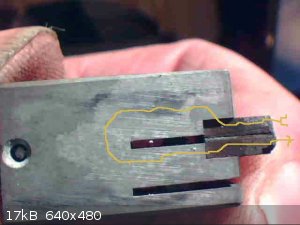
Below is pic of one of the two brush assemblies of a 240V 25A variac manufactured by Variac (a real variac lol). The two small blocks on the right
are the graphite brushes that make contact with the windings. A mica sheet insulates the two blocks from each other. So when the two blocks bridge and
short out adjacent wires the shorting current must flow the approximate path shown in yellow, a much longer path than if the two blocks were a single
block. This reduces the shorting current to an acceptable level. The blocks are clamped in place by screw.
I don't know if all rotary transformers us this method.
Suprisingly in normal operation these blocks carry 12.5A and some variacs are rated at 500% of there nominal max current but only for very short
periods. Perhaps the heat sinking from the clamp helps a lot.
[Edited on 6-3-2017 by wg48]
|
|
|
Texium
|
Thread Moved
27-11-2023 at 11:11 |


