| Pages:
1
2
3
4 |
franklyn
International Hazard

Posts: 3026
Registered: 30-5-2006
Location: Da Big Apple
Member Is Offline
Mood: No Mood
|
|
@ 1 2 A X 7
Simple harmonic oscillation , whether damped or not , is barely a descriptor
of this circuit. To have oscillation you must first have a circuit, a condition
which in this case disappears immediately after it is turned on. Waveforms
describe voltage or current of energy storing circuit elements. The series RCL
circuit has 2 so it is a 2nd order circuit characterised by a sinusoid which is
a superposition of 2 other waveforms , either 2 sinusoids or an exponential
and ramp or 2 exponentials.
As the capacitor is discharged the step response waveform is practically a
DC current transient. The pulse comprises the energy occuring before and
immediately following the the peak power point as I have already described.
Resistance of the EBW will increase to a level comparable to that of an
incandescent lamp , becoming most of the resistance value of the circuit,
effectively consuming available power and damping any reactive component
response. A moot consequence since it is all done and overwith before the
capacitor has even entirely discharged and therefore before even the onset
of peak current. Horizontal scale is arbitrary , still the shark fin profile of the
current waveform is what you expect as conduction is switched off by the
now exploded EBW.
Discontinuous is a mathematical term denoting a break in the curve being
graphed, where the line ends and continues again at some level above or
below. http://mathworld.wolfram.com/Discontinuity.html
Current and voltage can only change in a continuous way at all times.
http://mathworld.wolfram.com/ContinuouslyDifferentiableFunct...
A discontinuous change means that energy has appeared or vanished with
no change in time. Since power is the derivative ( slope , or rate of change
of energy ) this implies infinite power , a condition which cannot be real.
This is similar to attempting to divide by zero.
http://mathworld.wolfram.com/Tangent.html
Note the line may instead change direction at some point indicating a change
or substitution of the initial depicted expression. This is piecewise continuous
http://mathworld.wolfram.com/PiecewiseContinuous.html , similar to a
compound curve ( one comprised of two joined differently formulated curves )
except the two expressions forming the composite line are not differentiable
where they join , said not to be "well behaved ". An example expression that
is not well behaved is a fractal , which is continuous but too jagged to be
describable using calculus. The superposition ( adding of expressions ) which
are individually curvilinear can also give rise to a composite pointed line.
See pdf page 4 of attachment - Analysis and Design of Linear Circuits ,
Zero State Response - pg 413
The step condition ( applying and removing power ) matters. Relaxation
oscillators and power controls employing SCR's most commonly exhibit this.
Pulse width modulation as it's called , is basic in power control electronics,
and the basis of Switch mode power supplies.
Relaxation oscillator
http://hyperphysics.phy-astr.gsu.edu/hbase/electronic/relaxo.html
http://en.wikipedia.org/wiki/Phase_control
" the transient solution has been solved millions of times by students "
Cetainly not from what explanation you have given. Succintly and clearly stated here
http://www.coilgun.info/theoryinductors/dampedoscillator.htm
For those who may care ,
I dusted off an introductory text from my college years.
The Analysis and Design of Linear Circuits - Roland E. Thomas & Albert J. Rosa , 1994
ISBN - 0 - 13 - 220005 - 8
copied the relevant pages including the derivation of applicable expressions.
This is attached below in the second PDF. The first PDF is more brief and concise.
Available online , I recommend this one _
Transient Analysis of Electric Power Circuits Handbook
http://rapidshare.com/files/12045279/EBC_transient_analysis_of_electric_power_circuits_handbook-ISBN10-0387287973.rar
RCL analysis is on book pages 113 , 135 , 143 , or pdf pages , 127 , 149 , 157
_____________________________________________________________
Now that everybody's eyes have glazed over I ask myself what incisive
insight has this assertion of 12AX7 lent to the present inquiry if any.
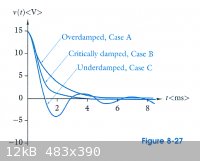
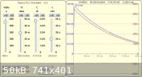
The only meaningful contribution to the depiction of discharge is that at
the start T= 0 the voltage curve as it appears in the 1st gif shown below ,
(figure 8.27 , from pg 437 )The Analysis and Design of Linear Circuits
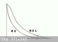
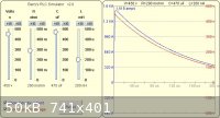
does not drop straight down and curve away as it does if only considered as an
R C discharge , seen for comparison in the 2nd gif attached alongside below.
It is instead rounded sinusoid at the top , because inductance impedes discharge
( superposition of 2 waveforms ). So the onset of discharge , as I had already
stated before , is very slightly delayed , to which 12AX7 adamantly exclaims ,
" Blatantly wrong ! please read up on RCL series resonance ".
Even at the rather extreme value of inductance of the cited textbook example,
1 Henry , the effect of inductive reactance is minor , considering the power
pulse will occur before T = 1. The range of resistance determining what damping
may occur shrinks to inconsequencial considering the EBW resistance rises from
negligeable to hundreds of times the total circuit resistance. This makes
nonsense out of any result from plugging static circuit values as constants into
a resonant circuit formula. The curve suggested describing the current , may well
do so and will terminate somewhere before it reaches its peak value.
What does it matter what might appear after ( providing a circuit still remained )
Even in other applications of pulse power , with a shunting " Fly-Back " diode
parallel with the capacitor so that reverse charging cannot occur ( known as
" free wheeling " ) there cannot be oscillation anyway , damped or otherwise.
In such case an undamped circuit prevails since current drops to zero before
the critically damped condition when current normally most quickly goes to zero.
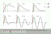
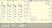
The 3rd gif attached below shows the effect of damping on a circuit. Omega ( ωd )
the resonant frequency in radians 1 /√LC is constant. The damping coefficient
Alpha ( α ) = R /2L varies. Since inductance ( L ) is common to both the only
thing which varies is ( R ). Increasing resistance R reduces amplitude height.
Because all have the same height this implies the voltage is being raised as
well. Only at extreme Resistance R is some minimal delay apparent of the peak
power point , indicated by a verticle red line always ahead of the peak current
marked in green.__________________________________________________
Some other resources available online
http://www.physics.uoguelph.ca/~leblanc/phys2470/labs/transients.pd...
Module 3 , Lesson 10 - RL , CL
http://nptel.iitm.ac.in/courses/Webcourse-contents/IIT%20Kharagpur/Basic%20Electrical%20Technology/pdf/L-10(GDR)(ET)%20((EE)NPTEL).pdf
Module 3 , Lesson 11 - RCL
http://nptel.iitm.ac.in/courses/Webcourse-contents/IIT%20Kharagpur/Basic%20Electrical%20Technology/pdf/L-11(GDR)(ET)%20((EE)NPTEL).pdf
Attachment: R C L Transients Electrical Technology.pdf (248kB)
This file has been downloaded 892 times
Attachment: Analysis and Design of Linear Circuits.pdf (1.7MB)
This file has been downloaded 838 times
|
|
|
franklyn
International Hazard
Posts: 3026
Registered: 30-5-2006
Location: Da Big Apple
Member Is Offline
Mood: No Mood
|
|
@ damn2
scroll down to see fig 14 , and read that following paragraph
http://[/color]sound.westhost.com/articles/capacitors.htm
Described is the performance of the sort of capacitor I favor.
The graphed profile is seen in the attached RCL simulation gif below
This execellent RCL calculator allows you to determine circuit parameters
by simply varying component values rather than mathematically plotting
their graphs. http://[/color]www.coilgun.info/mark2/rlcsim.htm
The slider bars value scale is checked up or down at the top the chosen
value is indicated below each one and along the top of the graph window.
According to the author the scales for C & L are graduated in uF & mH
but I find micro-microFarad a confusing term for pico farad and the same
with calling a Farad , Mega-microFarads.
As it is with ESR, so it is with ESL ( Equivalent series inductance ).
Resonant frequency remains unchanged for capacitors in parallel because
the inductance of individual caps does not change. Inductances in parallel
just as resistors in parallel, the equivalent inductance is greatly diminished.
Since capacitance adds together , the product with inductance remains the
same, and so does resonant frequency. There is no conflict with the RC time
constant. Just as resistors in parallel, ESR of caps in parallel is also greatly
diminished , since capacitance adds together , the product with resistance
remains the same , and so does the RC time. Whether one cap or many of
the same type in parallel , the resonant low impedance point of a whole
bank is the same as for one capacitor, provided the connecting bus is a low
inductance as the rest of the transmission line.
Actual caoacitance value of electrolytic types varies + / - 10 % at least
so the response of several acting together is their average value.
Regarding
http://www.sciencemadness.org/talk/viewthread.php?tid=12414&...
It is not useful when current and voltage switch polarity and have zero value.
This then is a problem of commutation, easily solved by having an SCR trigger
a Trigatron into conduction in series with the EBW , at or near peak line voltage.
Forget alternations , think of this as a DC source during a short time interval.
If you believe any small wire will respond with only a fizzle you must buy your
wire in some other universe.
High performance capacitors
http://[/color]www.sbelectronics.com/power_ring_division/new_laser_pulse_power.html
Yes when I can , I do read _
1. Exploding Wires Volume 1 , Chace, W. G. - Moore, H. K. , 373 pages , Plenum , 1959 ( out of print )
2. Exploding Wires Volume 2 , Chace, W. G. - Moore, H. K. , 321 pages , Plenum , 1962 ( out of print )
3. Exploding Wires Volume 3 , Chace, W. G. - Moore, H. K. , 410 pages , Plenum , 1964 ( out of print )
4. Exploding Wires Volume 4 , Chace, W. G. - Moore, H. K. , 348 pages , Plenum , 1967 (- in print -)
- http://[/color]www.dtic.mil/srch/doc?collection=t3&id=AD0759669 - see distribution statement at bottom
5. The Generation of High Magnetic Fields , Parkinson, David H. - Mulhall, Brian E. , 165 pages , Plenum , 1967 ( out of print
)
6. Pulsed High Magnetic Fields; Physical Effects & Generation , Knoepfel, H. , 372 pages , Elsevier , 1970 ( out of print
)
7. High Speed Pulse Technology Volume 3 , Capacitor Discharge Engineering , Frungel, F. , 498 pages , Academic Press , 1976 (
out of print )
8. Megagauss Technology and Pulsed Power Applications , Fowler, C. M. - Caird, Erickson , 879 pages , Plenum , 1987 ( out of
print )
9. High Power Switching , Vitkovitsky, Ihor , 304 pages , Van Nostrand Reinhold , 1987 ( out of print )
10. High Power Electronics , Sarjeant, W. J. - Dollinger, Richard E. , 392 pages , Tab Professional & Reference Books ,
1989 ( out of print )
11. Gas Discharge Closing Switches , Schaefer, Gerhard , 569 pages , Plenum , 1991 (out of print)
12. Introduction to High Power Pulse Technology , Pai, S. T - Zhang, Q. , 307 pages , World Scientific , 1995 ( out of print )
13. J. C. Martin on Pulsed Power , Martin, T. H. , et al , 546 pages , Plenum , 1996 ( out of print )
14. Fields & Transients in Superhigh Pulse Current Devices , Shneerson, G. A. , 561 pages , Nova Science , 1997 ( out of
print )
15. Pulsed Power , Mesyats, Gennady A. , 568 pages , Springer , 2004 ISBN 0306486531 (- in print -)
-
16. Exploding Wire Detonators: Resistivity Functions and Initiation Criteria for Circuit Calculations , Blackburn, J. H. , Muller, G. M. ,
CR-69-3201 , June 1959
17. Detonator Circuit Calculations:Resistivity Functions , Blackburn, J. H. , Muller, G. M. , OC-CR-68 , May 1958
18. A Theoretical Model of the Resistance Behavior of Exploding Wires , Tucker, T. J. , OC-RR-71 0739 , January 1972
_ _ _ _ _ _ _ _ _ _ _ _
I'll see you , and raise _
Scaling Underwater Exploding Wires
http://handle.dtic.mil/100.2/AD633115 , This redirects to the next link below
http://www.dtic.mil/cgi-bin/GetTRDoc?AD=AD633115&Location=U2&am...
EBW1 - a computer code for the prediction of the behavior of electrical circuits containing exploding wire elements
http://http://www.osti.gov/energycitations/servlets/purl/4229184-1IbmTb
Formation & Evolution of Plasmas from Single Exploding Wires
http://http://www.prod.sandia.gov/cgi-bin/techlib/access-control.pl/2002/0...
This one is just ridiculus _
Exploding Wire Initiation
http://http://ntrs.nasa.gov/archive/nasa/casi.ntrs.nasa.gov/19690013624_1969013624.pdf
Read last paragraph of ' General system description ' page 2 , note the time scale for discharge.
Oscillographic & Schlieren-streak Photographic Investigations of an Exploding Wire Discharge
http://http://www.physics.re.kr/resource/wop.pdf/J01/1984/017/R02/J0119840...
|
|
|
dann2
International Hazard
Posts: 1523
Registered: 31-1-2007
Member Is Offline
Mood: No Mood
|
|
Round and around we ..................
Hello,
Holy moses Sir Frequelin. I am not going to read all that!!!!!!!!!!!!!!!!
I hope you have learned (from your not inconsiderable reading splurge) that you need a low (not you average electrolythic or even a 'photographic
flash tube electrolythic') inductance capacitor in an exploding-wire-set-up, when you want a wire to explode in such a fashion that it will also
initiate a secondary explosive (RDX, PETN seem to be the one's that are used) placed in very close proximity to it.
It's the econony inductance stupid, sums it up well for me. Most of that problem inductance is in you average capacitor. Of
course you need low ESR and proper feed wires/lines etc but the internal inductance in the capacitor is our biggest problem for ultimate dumping of
the cacpacitors energy into where we want to get it in a suitable short time frame
BTW, I did not read all that (hopefully helpful for yourself) reading stuff that I suggested you should read. Just posted a few bits of it in some
post or other above. You were argueing along the lines of:
It's not the inductance stupid, inductance (in the capacitor) is not relevent etc etc, which is simple wrong.
Your posts are very verbose!!!!!!!!
dame2 out, over to dame1 
Dann2
]
[Edited on 2-8-2009 by dann2]
|
|
|
watson.fawkes
International Hazard
Posts: 2793
Registered: 16-8-2008
Member Is Offline
Mood: No Mood
|
|
I would recommend that anybody reading this completely ignore anything franklyn has to say about mathematics. At best, it's confusing. At worst, it's
not only wrong, it's wrong-headed, like the following:
Quote: Originally posted by franklyn  | | Current and voltage can only change in a continuous way at all times. [...] A discontinuous change means that energy has appeared or vanished with no
change in time. |
Let's start at the beginning. Continuity is a property of a mathematical model, not of
reality. Confusing these two is always a bad idea. There are plenty of ordinary, useful, and relevant mathematical models that are discontinuous.
Boundary conditions (especially at conductors) in electromagnetism immediately spring to mind, as do shock waves. Apropos the present subject, it's
quite an ordinary thing to model the switch in a switching power supply as a discontinuous element. Whether or not it's "really" continuous or not is
irrelevant to whether the model is applicable, and, therefore useful.
The trouble is that discontinuous models are simultaneously easier to work with informally and harder to work with rigorously. This distinction is
embodied in that par excellance discontinuous model, the Dirac delta. Informally, it's a function; rigorously, it's a distribution. In any
case, the ante you have to pay to work with a discontinuous model is knowing how to work with the continuous one. In the present case, that means
knowing something about differential equations. If you can't do that, making claims about their discontinuous behavior is laughable.
Finally I'll address the specific claim that a discontinuity violate conservation of energy. In the general Hamiltonian case, which works just fine
for electronics (although not very much used), you have a Hamiltonian function on a set of configuration variables and a constraint manifold upon
which those configuration variables lie. The constraint manifold represents the topology of the circuit as manifested in conservation of current at
junctions and voltage around loops. (It's a linear submanifold, usefully.) The Hamiltonian represents the energy associated with each circuit element.
Lossy elements are represent by Hamiltonian terms with negative indefinite first derivatives. A non-constant Hamiltonian doesn't violate conservation
of energy; all it says is that you're modeling a non-closed system that's emitting heat into its environment. You can get discontinuities either in
the Hamiltonian function or by changing the constraint manifold (canonically, with a switch). Neither does anything a priori to violate
conservation laws.
|
|
|
12AX7
Post Harlot
Posts: 4803
Registered: 8-3-2005
Location: oscillating
Member Is Offline
Mood: informative
|
|
Ironically, physics creates discontinuities that are physically realizable. So it's not even true that electronics must succumb to continuity.
One example: Electromagnetic shockwaves are easy to create in a nonlinear medium, and are an excellent way to generate extremely sharp pulses
(picoseconds) -- not entirely a discontinuity, there isn't infinite bandwidth for that, but still, orders of magnitude sharper than the input.
Not that this specifically applies to the immediate case.
Tim
|
|
|
franklyn
International Hazard
Posts: 3026
Registered: 30-5-2006
Location: Da Big Apple
Member Is Offline
Mood: No Mood
|
|
@ damn2
" you need a low ( not your average electrolythic or even a 'photographic flash
tube electrolythic' ) inductance capacitor in an exploding-wire-set-up "
" the internal inductance in the capacitor is our biggest problem "
Can you provide comparative data of actual capacitors to support this view ?
Anyway read what I said in my first sentence above
" scroll down to see fig 14 , and read that following paragraph "
http://sound.westhost.com/articles/capacitors.htm
Also play with this RCL calculator I cited http://www.coilgun.info/mark2/rlcsim.htm
see if your preconceptions quoted above are supported.
_______________________________________________
Online videos -
24 kJ rated bank but poorly coupled with wide cable loop ( there's your induction )
http://hackaday.com/2008/09/20/24kj-capacitor-bank
Direct link to the video - http://www.youtube.com/watch?v=UAgfGGjsoQM
Very much larger than it needs to be, but observe about a quarter into the
video when exploding items outside in the garage doorway. You can hear the
echo reflected from the distance of items exploded. As I said it must sound
like a rifle shot to achieve detonation status , as indeed this does.
This is at 600 volts , what I will consider maximum. Capacitance is not stated
but must be around 1500 - 2000 uF , it's very large , and so not an electrolytic.
http://www.youtube.com/watch?v=RnfhdaRz0f8
Other experimentor's results , small but effective
http://www.youtube.com/watch?v=WnMcXz08wuY
http://www.penguinslab.com/capdish.htm
I saw a video of this , don't know what became of it.
.
|
|
|
franklyn
International Hazard
Posts: 3026
Registered: 30-5-2006
Location: Da Big Apple
Member Is Offline
Mood: No Mood
|
|
It has been said by someone here that this is a scientific discussion.
Well , no , it's an engineering discussion , at least it is so for me.
Quoted here from the introduction to chapter 9 of the same text book
referenced futher up on circuit analysis.
The Analysis and Design of Linear Circuits
" LaPlace transforms have their roots in the pioneering work of the
Victorian British engineer Oliver Heaviside (1850-1925).
His operational calculus was essentially a collection of intuitive rules
that allowed him to formulate and solve a number of the important
technical problems of his day. Heaviside was a practical man with
no interest in mathematical elegance. His intuitive approach drew
bitter criticism from the mathematicians of his day. However,
mathematicians like Thomas John Bromwich and others eventually
recognized the importance of Heaviside's methods and began to
supply the necessary mathematical foundations.
The transformation is named for Laplace because a complete
mathematical development of Heaviside's methods was eventually
found in the 1780 writings of the French mathematician
Pierre Simon Laplace. "
Heaviside originated the terms " Inductance " and " Impedance "
@ watson fawkes
I entirely concur. One should not lend much credence to someone who does
not provide references nor supporting documentation , as if incomprehensible
incoherent double talk can pass for self evident truth. Trouble is, balderdash
like pissing upwind has a way of coming back at you. If credentials matter
at all then you have a bone to pick - not with me - but the authors of the
textbook excerpts I provided whose resumes are on the cover. Attached
additionally are the highlighted relevant passages.
When two Ph.D heads of engineering schools with backgrounds from Stanford ,
and jointly with the U.S. Air Force Academy and the Institute of Electrical and
Electronics Engineers , refute , and by implication indicate that you are full of crap ,
it is very likely to be true. No one can accuse you of heeding the well tested notion ,
it is better to remain silent and have people think that you are not the savant
you pretend to be , than it is to open your mouth and remove all doubt.
.
Attachment: Capacitor Power & Energy pg 342 ch 7.pdf (1.2MB)
This file has been downloaded 824 times
|
|
|
12AX7
Post Harlot
Posts: 4803
Registered: 8-3-2005
Location: oscillating
Member Is Offline
Mood: informative
|
|
Take a look at the 470uF 450V unit down around p.11,
http://www.epcos.com/inf/20/30/db/aec_07/B43305.pdf
Table says 290 mohm, and earlier (p.3) ESL is claimed as "approx. 20nH".
Applying these values to said RLC calculator produces an excessively overdamped hump, which peaks at 1546A after about 1us, followed by an essentially
RC decay over the following miliseconds. R*C = 1.3ms, so the largest part of the energy is spent over hundreds of microseconds, far too slow.
The way to speed it up is reduce C and, to conserve energy, raise voltage.
As for "sounds like a rifle", that's meaningless. A rifle is hardly an explosion, merely a rapid deflegration. But between detonation and
deflagration, the human ear can't tell the difference. Besides, even an electrolytic is faster than a rifle shot (if slower than a true detonation).
The only thing that matters is what actually happens, and that must be measured.
Tim
[Edited on 8-4-2009 by 12AX7]
|
|
|
watson.fawkes
International Hazard
Posts: 2793
Registered: 16-8-2008
Member Is Offline
Mood: No Mood
|
|
| Quote: Originally posted by franklyn | | One should not lend much credence to someone who does not provide references nor supporting documentation , as if incomprehensible incoherent double
talk can pass for self evident truth. |
The reason to ignore franklyn about mathematics is that, for all his
citation, he doesn't understand the content of his citations well enough to draw correct conclusions from it. His recent, arrant declamations about
continuity of functions and energy conservation are evidence of this.
More generally, there's good reason to distrust anybody who can't make a short argument in their own words about a specific subject. In franklyn's
case, you have long and rambling posts about lots of things all at once with no separation of issus and extensive citations with little specificity.
Insisting upon the weight of authority is an old rhetorical tactic, but when there's an interpreter between the authority and you, my dear reader,
should evaluate the interpreter first to see if the authority claimed is relevant.
|
|
|
dann2
International Hazard
Posts: 1523
Registered: 31-1-2007
Member Is Offline
Mood: No Mood
|
|
Hello,
Attached patent using no wire, just a spark gap.
Time of discharge in the order of a few micro seconds.
EDIT. I bit strange, the patent is dated 1976 and it was filed in 1950? Misprint I suppose
Dann2
Attachment: US3955505.pdf (188kB)
This file has been downloaded 718 times
[Edited on 5-8-2009 by dann2]
|
|
|
franklyn
International Hazard
Posts: 3026
Registered: 30-5-2006
Location: Da Big Apple
Member Is Offline
Mood: No Mood
|
|
@ 1 2 A X 7
I'm glad you're finally looking at this as real objects. So what has all that B.S.
over the last 2 pages of this thread meant after all. This is a perfectly sensible
and studied retort to my premise , thank you for that
R C time of the cited 470 uF capacitor , examined alone , is actually 10 times
faster ( 0. 290 ohm ) x ( 0. 000470 , Farad ) = 0. 00013 sec ( 130 microseconds )
this in the upper time range of what is known to produce explosion.
( obviously a whole circuit adds to the values of R & L )
" far too slow " , only in deference to the known way in which these things are
usually done , which is not in dispute. The rise time for current of a billion amps
per second is a well established parameter. This means that in the first nanosecond
there is a 1 amp current , after 2 nanoseconds it has risen to 2 amps by one
microsecond current will be 1000 amps. You will note that this precondition
is well met by the example you give seen in image gif 1. What energy is required
to achieve explosion is then a matter of time and the area beneath the
power curve ( volts X amps , not in view ).
I agree 1.3 millisecond is a long time for an event of this kind , if the energy supplied
is limited. As you point out " to conserve energy, raise voltage " , but then it really
depends on what power level is available wouldn't it. A 1.3 millisecond pulse of the
same high level or nearly so will accomplish the same result. The EBW is not going to
hold off exploding just because it continues receiving power beyond a shorter pulse.
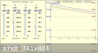
In the gif 2 image 10 capacitors in parallel yield 4700 uf and ESR & ESL drop to 1/10
the value for the bank as a whole from 290 mohm to 29 , and from 20 nH to 2 nH.
The time scale remains unchanged but because the currents of 10 capacitors add
together total current is now 10 times greater and therefore so is the power supplied.
I don't see a problem
" sounds like a rifle ", is not meaningless , it's an indicator. One will at least need to
hear that to warrant further investigation and confirmation. I'm sure no one has
experienced a bridge wire explosion that is quiet , though a fizzle will not be as loud.
___________
Finagling
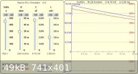
In image gif 3 inductance is raised to the original 20 nH to better view the whole
graph. R C time is 130 usec , the time for what is the useful pulse is 1.5 R C =
195 usec seen at the right side at the 100 volt level when 95 % of the energy
has discharged. Inductive reactance is only now just noticable as voltage and
ESR remain unchanged , the peak current has dropped from 15.5 kiloamp to 15.2
kiloamp as some energy has instead gone into induction.
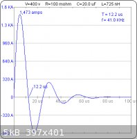
In image gif 4 inductance is raised 10 times to 200 nH on a one 290 milliohm
470 uF cap delaying the 1500 amp peak current onset 4 microseconds. Dividing
1500 kiloamps by 4 is 375 , little more than a third of the 1000 amps per usec
rise time required. This is a failure mode for a short pulse scheme. Raising the
voltage compensates for this.
Raising the power by increasing capacitance as in gif 2 will compensate for this
just the same. Dividing 15.5 kiloamps by 4 is 3875 amps , well beyond where the
rise time becomes marginal.
In image gif 5 ESR is reduced to 29 milliohm and the nearly critically damped actual
R C L discharge time is now just 43 usec. R C time ( 0. 029 ohm )
x ( 0. 000470 , Farad ) = 0. 000013 ( 13 microseconds ), times 1.5 is 19.5 usec
just half of the R C L value. The ESR of just 29 milliohm is that of some film or oil
capacitors and with the voltage remaining unchanged the peak current is now
6.6 times greater at 10 kiloamps. Reducing inductance back to 20 nH will also
increase peak current by little more than a third to 13.8 Kiloamp. Doubling the
voltage also doubles the current and will increase the power by 4 times.
By C( V x V ) / 2 , the 10 cap bank is , ( 0. 0047 F) x ( 450 x 450 ) / 2 = 476 Joules
At double the voltage the 470 uF capacitor is , ( 0.00047 F ) x ( 900 x 900 ) / 2 = 190 Joules
Average power for the 10 cap bank is 476 Joules / .000195 sec = 2.4 megawatts
Average power for the 900 volt 470 uF capacitor is 190 Joules / .0000195 sec = 9.7 megawatts
Of course the capacitance can be enlarged all you want. 4 times as many electrolytic
capacitors , a total of 18800 uF will yield equal power output. As already explained the
discharge time remains 195 microseconds. One could instead use 2 times or just 20
parallel capacitors in series with the a.c. powerline ( as initially described in this thread )
to achieve the same power rating at discharge. This would be a discharge of ~ 1974 Joules ,
10 times as much , since the pulse width is 10 times more than the 900 volt capacitor.
___________
Minor issues are that the EPCOS capacitor cited is a filter capacitor and the ESR
at 290 milliohms is somewhat high , rather than the type specific for high current
discharge in strobe and photoflash applications. ESR totals slightly lower with fewer
large capacitors than more smaller ones. Compare the ones on page 8.
[Edited on 5-8-2009 by franklyn]
|
|
|
franklyn
International Hazard
Posts: 3026
Registered: 30-5-2006
Location: Da Big Apple
Member Is Offline
Mood: No Mood
|
|
Pay no attention to the man behind the curtain
' I ' am the all and powerful OZ
says watson.fawkes
" interpreter between the authority and you ".
Interpretive mathematics , that's a good one 
As an adept specious prevaricator you have no equal.
looking forward to seeing your " theorems "
published in a peer reviewed journal
.
|
|
|
dann2
International Hazard
Posts: 1523
Registered: 31-1-2007
Member Is Offline
Mood: No Mood
|
|
Quote:
_________________________________________
R C time of the cited 470 uF capacitor , examined alone , is actually 10 times
faster ( 0. 290 ohm ) x ( 0. 000470 , Farad ) = 0. 00013 sec ( 130 microseconds )
this in the upper time range of what is known to produce explosion.
__________________________________________
Where did you get the figure of 130 microsec from and what exactly do you mean by 'explosion'.
If the 'explosion' does not initiate PETN or hopefully RDX then it's not what the thread is about.
Another diva break below. This type of setup will not do the required task, no
matter how impressive, loud or funny it may be.
http://www.youtube.com/watch?v=KxeUV7CXrlI
Dann2
[Edited on 5-8-2009 by dann2]
|
|
|
12AX7
Post Harlot
Posts: 4803
Registered: 8-3-2005
Location: oscillating
Member Is Offline
Mood: informative
|
|
Of all things, I decided to build a high voltage power supply tonight, good for 150-400V at up to 30mA. But this is perfect for charging fairly large
capacitors, which invited me to add a xenon flash tube and trigger transformer. So I did.
So I hooked up a rather beefy 20uF film and oil capacitor (probably good for lots of amps, with moderate ESL) to the flash tube, and despite not
having a storage scope, I managed to obtain this image:

Setup involves shorting the probe with its ground lead, placing the loop thus formed right near the capacitor terminals, thus capturing some EMI.
Vertical is uncalibrated, since that would be rather hard to do. It should be current, or possibly the derivative. Time is 10µs/div, as shown.
Assuming the tube is a direct short (not a bad assumption, at least for the first 16 microseconds), the discharge looks a lot like a damped sinusoid
with pseudoperiod of about 24us. This implies an inductance of 0.73uH. Since it's decaying fairly rapidly (after about 2 cycles), Q = 2 roughly, so
resistance is (very roughly) 100 miliohms. I would expect the wiring and capacitor to contribute only a few miliohms, so most of that loss must be in
the xenon (good, that means it should be fairly efficient as far as heating up the xenon plasma).
As you can see, these figures are consistent with the respective RLC plot, which bears a striking resemblance to the oscillograph (at least until
things change).
After 22us, I think the xenon cooled down enough that ionization slowed down. At this point, terminal voltage must've risen to a fairly constant
value (the current magnitude seems to fall linearly). As the plasma continued to cool, voltage and current decayed exponentially with time, resulting
in the ~40us tail seen after the main transient.
I'm not sure how much charge was left in the cap after a shot, maybe 30V. My supply has bleeder resistors, so I didn't measure it.
Incidentially, this 1.6J shot seems to have about enough dI/dt and speed to fire the kinds of things talked about in this thread. Interesting to find
out what an electrolytic will do.
Tim
|
|
|
merrlin
Hazard to Others
Posts: 110
Registered: 3-4-2009
Member Is Offline
Mood: No Mood
|
|
| Quote: Originally posted by dann2 | Hello,
Attached patent using no wire, just a spark gap.
Time of discharge in the order of a few micro seconds.
EDIT. I bit strange, the patent is dated 1976 and it was filed in 1950? Misprint I suppose
Dann2
[Edited on 5-8-2009 by dann2] |
No, it is not a misprint. The Johnston patent (US3955505) was subject to a secrecy order due to its potential for application to nuclear weapons.
Nice find.
|
|
|
dann2
International Hazard
Posts: 1523
Registered: 31-1-2007
Member Is Offline
Mood: No Mood
|
|
Hello,
I recall on the news back in the early ninteys where there was a report about some entity from Iraq attemting to obtain fast discharge capacitors from
Germany? or USA?
It showed Sadam with a capacitor in his hand at a news conference boasting that they did not need to import them as the one in his hand had been made
at the local university.
Link here to a guy discharging caps through an air flash tube. He stressed the need for low inductance caps.
http://www.technology.niagarac.on.ca/staff/mcsele/lasers/Las...
Link to caps here. (scroll down) They say they are good for 'slapper' applications. Not too cheap$$$$$$$$$£££££££££
http://www.amazing1.com/capacitors.htm
Specialized Low Inductance Capacitors for Ultra High Current Discharges
These low inductance capacitors are excellent for EMP shock pulse generators, exploding wires, Marx impulse generators, Slapper detonators, plasma
focused neutron enriching, gas discharge lasers, thermonuclear research, high magnetic fields, etc.
How would you make a capacitor that would have fast discharge and be simple to make. Would simple layers of Al (or Cu) foil and oil soak insulation
be with a connnection comming out of each layer be OK. Minimum size etc not required.
Or would you be better off with a lot of smaller (purchased) caps connected together (as per 12AX7 cap).
Dann2
|
|
|
BertHickman
Unregistered
Posts: N/A
Registered: N/A
Member Is Offline
|
|
"How would you make a capacitor that would have fast discharge and be simple to make. Would simple layers of Al (or Cu) foil and oil soak insulation
be with a connnection comming out of each layer be OK. Minimum size etc not required.
Or would you be better off with a lot of smaller (purchased) caps connected together (as per 12AX7 cap)."
It really depends on the desired operating voltage and capacitance. Low inductance homemade HV capacitors can be made using aluminum foil or thicker
aluminum flashing separated by polymer dielectrics such as Mylar, Polyethylene, or Polypropylene. Typically, two layers of thin dielectric should be
used between plates to reduce punch through from material defects. Operation at voltages above 2 kV may require oil immersion on order to prevent
corona. Corona can rapidly destroy the polymer dielectric, particularly at plate edges where the electrical field is most intense.
There is an art to minimizing capacitor inductance in the capacitor and in the external circuit. Constructing your cap as a flat plate capacitor will
help. Simple very low inductance flat plate HV capacitors have been successfully used in the construction of home brew nitrogen lasers. In the
external circuit, the key is to minimize the enclosed area within the discharge current loop. Use coaxial, or identical size/shape overlapping flat
conductor plates, separated by a dielectric to form a stripline, so that the sending and return current paths are in close proximity - this helps to
cancel magnetic fields from the current flow, and thus the loop inductance and also helps reduce resistive losses due to skin effect for very high
di/dt discharges.
If you need significantly more energy, a bank of series/parallel polypropylene "snubber" capacitors can be used. The series path on each "chain"
should be connected in a zig-zag fashion to help reduce inductance (similar to the way a non-inductive resistor is constructed). Google "MMC
Capacitors" for part information and construction details (these are used extensively in low-medium power Tesla Coils).
If even more energy is required, a professionally constructed low inductance "energy discharge" capacitor is usually the most cost effective solution.
These are sometimes available from the surplus marked and off eBay. These will normally have a metal case, and one or two wide, low-profile
insulators. Capacitors with large "Frankenstein" insulators are usually NOT low-inductance capacitors. Example of some good low inductance energy
discharge caps can be seen here (1700 pounds worth!):
http://www.capturedlightning.com/frames/gallery/maxcap3.jpg
Bert
|
|
|
franklyn
International Hazard
Posts: 3026
Registered: 30-5-2006
Location: Da Big Apple
Member Is Offline
Mood: No Mood
|
|
@ damn2
Get these books NOW while they are still available.
Pulse Power Formulary - Richard J. Adler
http://www.isi.edu/~vernier/pp_formulary.pdf
Introduction to high power pulse technology - S. T. Pai, Qi Zhang
Photocopy PDF ( This is also available on Google books to preview )
http://rapidshare.com/files/43877945/ITHPPT.rar.html
http://rapidshare.com/files/43784543/ITHPPT.pdf
High-speed signal propagation - Howard W. Johnson, Martin Graham
CHM format - from any of these ( also available on Google books to preview )
http://rapidshare.com/files/100072803/High.-.Speed.Signal.Pr...
http://rapidshare.com/files/14647580/High-Speed.Signal.Propa...
http://rapidshare.com/files/9411784/013084408X_chm.rar.html
http://uploading.com/files/OZXMD2F4/SignPropag.rar.html
See the following , it refers mostly to circuit boards but the same principals apply.
Chap 1 Fundamentals
- 1.3 - Rules of scaling
- 1.4 - Concept of resonance
Chap 2 Transmission Line Parameters
- 2.3 - Ideal Transmission line
- 2.6 - Skin Effect
- 2.7 - Skin Effect Inductance
Chap 3 Performance Regions
- 3.4 - Lumped Element Region
- 3.5 - R C Region
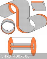
The most compact form of a capacitor is a roll of plastic with both surfaces metalized
leaving one border on both sides on opposite edges without metal surfacing. See attached.
Two lengths of the ribbon is spooled together with each folded back over the other. The
ends are dipped into a silvering solution to provide a base for a light electroplating of metal.
Finally an exact sized end plate of tinned copper is heated only just enough to melt the solder
surface onto which the plated end of the capacitor is pressed joining to the solder surface.
Each end is now a terminal , one end can be connected by a copper tube down the center
of the core tube to a coaxial connector situated in the center of the opposite end.
The metalized roll as described may be improvised from more readily availble plastics which
are metalized only on one side but without the border. Two are placed with the metalized
surfaces together , and two of these sandwiches are then rolled togther slightly offset to
make up for the missing border. The cylinder is now wrapped in a laminate for protection
leaving a shallow brim at the ends to apply clear polyurethane varnish. It is subjected
to vacuum to draw out trapped air to seep the varnish into the crevices. After the ends
are dry they must be trimmed to expose the metalic edging. The rest of the proceedure
remains the same.
Metallized Polyester Film is the material of choice having a dielectric strength of 7000 volts
per mil ( thousanth of an inch thickness ) or 25 microns. A capacitor of 25 centimeters in
diameter by 50 centimeters long will fit into an athletic tote/duffle bag. When charged from
12 to 14 thousand volts ( two ply mil film ) it should store 10000 Joules or more. Here Is a
sampling of sources which may serve your requirments.
Metallized Polyester Film
http://paperandfilm.com/metallizedfilmmetallizedfilms.aspx
http://paperandfilm.com/polyesterfilm.aspx
http://www.grafixplastics.com/mylar_types.asp
Electrical properties
http://www.grafixplastics.com/mylar_prop.asp
http://www.petfilm.com/specifications.html
Sizes
http://www.grafixplastics.com/mat_thick.asp
http://www.petfilm.com/tools.html
Custom rolling
http://www.grafixplastics.com/laminating.asp
Dielectric strength , measured in volts per unit thickness , is the maximum voltage that an
insulator can withstand without breakdown. It largely determines the energy density of a
capacitor , since energy density is proportional to the square of the dielectric strength.
Doubling the voltage for the same capacitance will reduce capacitor volume to 1/4 whiile
retaining the same energy.
The dielectric constant k is the measure of the permittivity ε of an insulating material.
The dielectric constant increases capacitance by the factor , k , times.
http://www.clippercontrols.com/info/dielectric_constants.html
If high energy density is required, one should use insulation having a large dielectric constant
as the capacitance is directly proportional to , ε. High energy density capacitors such as
aluminum electrolytics discharge slow. If a high rate of discharge is desired, then use
insulation of small dielectric constant as the electromagnetic wave speed ( velocity factor )
is inversely proportional to the square root of , ε , 1/√ε , also given as , k , 1/√k.
The question of how to model the circuit depends on the time frame of discharge.
Essential preconditions are a current rise time of a billion amps per second. After
a peak of 15000 or better the ideal waveform should approximate a squarewave.
- See attached copied from Introduction to high power pulse technology
In practice it is nearly impossible to discharge any paper or plastic capacitor in less than 100
nanoseconds. The pulse width can be narrowed by a delay line. Pulse width can be set by
the length of the transmission line relative to the capacitor's discharge time and the value
of permittivity ε of its coaxial insulator the dielectric constant ' k '.
A higher dielectric constant in a transmission line increases the line capacitance lowering
its impedance which slows the speed of transmission increasing the delay and compressing
the width of the pulse. A given dielectric constant ' k ' has the effect of reducing transmission
line impedance by the factor , 1/√k times , and increasing the transmission line delay by
the
factor , √k times. http://www.radio-electronics.com/info/antennas/coax/coax_velocity_f...
For example a 100 nanosecond discharge fills 30 meters of common polyethylene coaxial cable ,
dielectric constant ε being ~ 2.2.
.0000001 sec X 300000000 meters/sec ( speed of light ) = 30 meters
( 1 / √ 2.2 ) = .67 , times 30 meters = 20.1 meters
Glycerine with an ε of 44 to 68 , will reduce the length 6.6 to 8.3 times , down to
4.5 to 3.6 metes
From this it is seen that optimally a short pulse generating system should be comprised of a
high voltage capacitor with a low dielectric constant discharged into a transmission line of
high dielectric constant.
See - 2.3 - Ideal Transmission line , in
High-speed signal propagation
http://www.allaboutcircuits.com/vol_2/chpt_14/3.html
High constant dielectrics such as glycerine , being fluid require custom tube assemblies made to
provide the required characteristic impedance which is determined by the geometry.
See book page 51 , pdf page 31 of
Introduction to high power pulse technology
.
[Edited on 9-8-2009 by franklyn]
|
|
|
watson.fawkes
International Hazard
Posts: 2793
Registered: 16-8-2008
Member Is Offline
Mood: No Mood
|
|
| Quote: Originally posted by 12AX7 | One example: Electromagnetic shockwaves are easy to create in a nonlinear medium, and are an excellent way to generate extremely sharp pulses
(picoseconds) -- not entirely a discontinuity, there isn't infinite bandwidth for that, but still, orders of magnitude sharper than the input.
Not that this specifically applies to the immediate case. |
Upon some reflection, it might apply. Wouldn't an
EBW system be much easier to build if you could take a millisecond pulse and apply it through a pulse shaping line to sharpen it down to a
microsecond? The key, of course, is to find a cheap and easy way of constructing the pulse shaper. If there were a suitable non-linear dielectric, you
could build a small coax line out of copper plumbing pipe.
Any ideas for a commonly-available non-linear dielectric? I'm afraid my knowledge of electrical properties of materials is not broad enough to have
anything in my head.
|
|
|
not_important
International Hazard
Posts: 3873
Registered: 21-7-2006
Member Is Offline
Mood: No Mood
|
|
Barium strontium titanate is one http://202.127.1.11/msb/99/9917.pdf
Almost any of the "transducer crystals" are, although some need rather high field strengths to exhibit much non-linearity. Zinc oxide is to a degree.
|
|
|
12AX7
Post Harlot
Posts: 4803
Registered: 8-3-2005
Location: oscillating
Member Is Offline
Mood: informative
|
|
If you can get a slab of metallized barium titanate, that would work. If not, about a thousand ceramic chip capacitors laid in a row will also work
(minimum pulse width being determined by the effectively lumped-constant construction; roughly, the electrical distance between capacitors, or maybe
10ps for adjecent chips).
The shock line has to store as much energy as you put into it, so it would be rather useless to take a lazy milisecond pulse and sharpen it up. Heck,
you can short one end of the line in nanoseconds quite easily, just use its energy directly. The purpose of shock lines is to sharpen fast pulses to
insanely fast pulses. We're talking pulses much faster than needed here.
Tim
|
|
|
franklyn
International Hazard
Posts: 3026
Registered: 30-5-2006
Location: Da Big Apple
Member Is Offline
Mood: No Mood
|
|
very funny
you guys stick to what you know - razzing
SAW's ( surface acoustic wave ) filters are as old as
crystal radios and about as useful - in small signal electronics
" non-linear " , I'll say , if you subject piezo ceramics to a
several hundred Joule discharge , you will successfully
explode the ceramic !
http://cat.inist.fr/?aModele=afficheN&cpsidt=16583410
http://www.iop.org/EJ/abstract/0022-3727/38/5/016/
not_important , can't believe you don't know that.
___________________________________________
Intrinsic polarization of ferroelectric thin films means they may
serve as a dry insulator in place of electrolytic dielectrics such as
are formed on aluminum, but with a much higher dielectric strength
enabling high charging voltage. The very high dielectric constant
typically in the hundreds , may provide capacitance between that
of supercapacitors and aluminum electrolytics. As already explained
this cannot be a quick to discharge capacitor material. Ferroelectric
properties of Perovskites have been the subject of study since the
second world war. If this could be any use in tranmission lines with
the intent of high power pulse forming it would have been developed
by now.
New
Pulsed Power at Sandia National Laboratories, the first forty years
http://www.sandia.gov/pulsedpower/newsreleases/reports/Pulsed_PWR_1...
Reposted due to errors
Scaling Underwater Exploding Wires
http://handle.dtic.mil/100.2/AD633115 , This redirects to the next link below
http://www.dtic.mil/cgi-bin/GetTRDoc?AD=AD633115&Location=U2&am...
EBW1 - a computer code for the prediction of the behavior of electrical circuits containing exploding wire elements
http://www.osti.gov/energycitations/servlets/purl/4229184-1IbmTb/42...
Formation & Evolution of Plasmas from Single Exploding Wires
http://www.sandia.gov/pulsedpower/prog_cap/pub_papers/022801.pdf
This one is just ridiculus _
Exploding Wire Initiation
http://ntrs.nasa.gov/archive/nasa/casi.ntrs.nasa.gov/19690013624_1969013624.pdf
Oscillographic & Schlieren-streak Photographic Investigations of an Exploding Wire Discharge
http://www.physics.re.kr/resource/wop.pdf/J01/1984/017/R02/J0119840...
.
[Edited on 10-8-2009 by franklyn]
|
|
|
12AX7
Post Harlot
Posts: 4803
Registered: 8-3-2005
Location: oscillating
Member Is Offline
Mood: informative
|
|
WTF, that article is 2005?! Tektronix and HP must've been using shock lines for well over a decade!
Tim
|
|
|
merrlin
Hazard to Others
Posts: 110
Registered: 3-4-2009
Member Is Offline
Mood: No Mood
|
|
| Quote: Originally posted by franklyn |
" non-linear " , I'll say , if you subject piezo ceramics to a
several hundred Joule discharge , you will successfully
explode the ceramic !
|
If you are going to talk about "exploding" piezo ceramics, it is insufficient to specify energy alone. You should specify the energy density, (e.g.,
joules/cc). Aside from the trivial solution of using a large volume of ceramic to store a few hundred joules, thin single crystal titanates can have
significant energy storage densities due to the high fields that can be achieved.
|
|
|
watson.fawkes
International Hazard
Posts: 2793
Registered: 16-8-2008
Member Is Offline
Mood: No Mood
|
|
| Quote: Originally posted by 12AX7 | | The shock line has to store as much energy as you put into it, so it would be rather useless to take a lazy milisecond pulse and sharpen it up. Heck,
you can short one end of the line in nanoseconds quite easily, just use its energy directly. The purpose of shock lines is to sharpen fast pulses to
insanely fast pulses. We're talking pulses much faster than needed here. |
I understand that the existing
technology makes very fast pulses (picosecond and femtosecond), but the mathematics of pulse sharpening have everything to do with the non-linearity
and nothing to do with the time scale. Whether a practical system can be made depends upon energy densities, magnitude of non-linearities, frequency
dependence of the non-linear medium, hysteresis effects, etc.
I must say, however, that I doubt this idea will work, because you can't fit very much of even a microsecond pulse into a ten foot pipe.
|
|
|
| Pages:
1
2
3
4 |
|


