dann2
International Hazard

Posts: 1523
Registered: 31-1-2007
Member Is Offline
Mood: No Mood
|
|
Homebrew flowmeter
Hello,
I was trying to come up with a simple flowmeter to measure flow rate of acid. From zero to approx. 1.5 litres per minute was wanted. I was thinking
along the lines of a 'float' type. A clear tube with a body inside that rises up as the flow rate increases. The tube needs to be tapered. How might
you obtain a tapered hole in a (say) perspex block? How much of a taper is needed? I do not think I could do the tapered hole directly on a lathe.
(at least not the one I have!)
You could mould a block of resin (it is semi transparent) in a long square mould with a tapered insert. The insert could be made on a lathe. Perhaps
you need a very accurate taper. I am not looking for a very accurate flow meter. An indicator of ballpark flow rate is all that is needed.
Acid resistant flowrate meters are hard to come by or/and cost a lot.
A straight glass tube would be perfect (+ the float) if it could be got to work. Glass tubes are cheap and easy got. If a teflon coated magnetic
stirrer bar of appropriate size was inserted in the tube and a coil (inductor) was placed at the top (the outlet) of the tube so that as the stirrer
bar was pushed up (by the force of the flow) the repelling action of the coil got larger and larger so that position of bar give an indication of
flow.
Perhaps a large magnet would do the same job and eliminate the need for an electrical supply.
Would that work?
Anyone any other whacky suggestions on how to use a parallel walled tube to do the job?
Cheers,
Dann2
|
|
|
hinz
Hazard to Others
Posts: 200
Registered: 29-10-2004
Member Is Offline
Mood: No Mood
|
|
Or better drill a hole at the bottom of a vertical pipe and use the height of the fluid inside the pipe as a static pressure indicator and thus get
the fluid flow trough the hole at the bottom of the pipe.
Or you can buy a "rotameter", the thing you're looking for from a supplier. Those guys have a glass lathe and other nifty tools and can make tapered
tubes with it.
http://en.wikipedia.org/wiki/Rotameter]
[Edited on 20-9-2009 by hinz]
|
|
|
Magpie
lab constructor
Posts: 5939
Registered: 1-11-2003
Location: USA
Member Is Offline
Mood: Chemistry: the subtle science.
|
|
Consider making your own orifice meter. It's just a plate with a hole in it that inserts between two flanges in the pipe. You then correlate the
pressure differential across the plate with flowrate.
http://www.engineeringtoolbox.com/orifice-nozzle-venturi-d_5...
[Edited on 20-9-2009 by Magpie]
The single most important condition for a successful synthesis is good mixing - Nicodem
|
|
|
dann2
International Hazard
Posts: 1523
Registered: 31-1-2007
Member Is Offline
Mood: No Mood
|
|
Looking at a 100ml seperation funnel, I wonder if I place a ball into it, it may do the job. More a visual indication than a flowmeter as the taper is
far too much.
What would you use to measure the pressure difference accross the orifice meter? It needs to be corrosion resistant
Wonder would this contraption
http://cgi.ebay.co.uk/ws/eBayISAPI.dll?ViewItem&item=290...
measure fluid velocity in any pipe. Velocity would be a measure of flow rate so long as you have an idea of pipe size.
Dann2
[Edited on 20-9-2009 by dann2]
|
|
|
Magpie
lab constructor
Posts: 5939
Registered: 1-11-2003
Location: USA
Member Is Offline
Mood: Chemistry: the subtle science.
|
|
The easiest and cheapest would be some kind of manometer, like standpipes, if your pressures aren't too great. I think the link I gave shows a sketch
of same.
Otherwise a differential pressure gage would work, but that could be expensive.
The single most important condition for a successful synthesis is good mixing - Nicodem
|
|
|
dann2
International Hazard
Posts: 1523
Registered: 31-1-2007
Member Is Offline
Mood: No Mood
|
|
Thanks for the suggestions.
I came accross the following:
http://www.builditsolar.com/References/Measurements/DIYFlowM...
It is pretty simple and cheap. It would be acid resistant for long enough for to get my job done too. Too big for what I want but will work on it.
Cheers,
Dann2
|
|
|
Magpie
lab constructor
Posts: 5939
Registered: 1-11-2003
Location: USA
Member Is Offline
Mood: Chemistry: the subtle science.
|
|
Yes, that is a venturi meter, which is also shown on the site I linked. It's probably easier to construct than an orifice meter. Good find. I have
seen both used in practice.
The single most important condition for a successful synthesis is good mixing - Nicodem
|
|
|
wpenrose
Harmless
Posts: 17
Registered: 17-6-2007
Member Is Offline
Mood: No Mood
|
|
A simple orifice meter:
A tee tube, with the branch pointing upward and connected to a longer tube with a measuring stick beside it.
On the downside of the tee tube, a restriction which could only be a piece of soft glass tubing pulled to a thin passage.
Flow through the tee and the narrowed tube causes increased pressure on the inlet side, forcing liquid up the branch tube, proportional to flow.
DB
|
|
|
Swede
Hazard to Others
Posts: 491
Registered: 4-9-2008
Member Is Offline
Mood: No Mood
|
|
Dann2, I think I know where you are going with this device. How about calibrating the delivery system as opposed to measuring flow? To get flow
requires pressure. The pressure can be created either by head pressure or by a pump, both of which can be controlled and/or calibrated, with an
acid-resistant flow-control valve adding further refinement to the system.
If it is a simple head-pressure rig, measure the volume loss vs. time, and theres your flow rate. Run it again with the valve set at some partial
setting, creating a flow graph.
|
|
|
watson.fawkes
International Hazard
Posts: 2793
Registered: 16-8-2008
Member Is Offline
Mood: No Mood
|
|
Quote: Originally posted by dann2  | | I was trying to come up with a simple flowmeter to measure flow rate of acid. From zero to approx. 1.5 litres per minute was wanted.
|
Take a look at Dwyer Instruments Series RM flowmeters. Even with stainless steel parts, the small ones are less than USD 40. Ordinarily I'm all in favor of building your own gear,
but this is pretty modest price, much less than for the equivalent range in welding gear. The 5-50 gallon/hour scale should work for you.
From the feel of the website, this seems like the kind of place that's willing to talk materials compatibility with no compunctions and indeed a
certain measure of curiosity.
|
|
|
dann2
International Hazard
Posts: 1523
Registered: 31-1-2007
Member Is Offline
Mood: No Mood
|
|
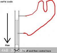
Flow meter woe's
Hello,
Made the simple flow meter as per the (terrible) diagram. The level of liquid (blue stained water) in the u-tube moves as flow changes. I did not get
around to doing any actual calibration.
Water is entering the u-tube and lodging in the u-tubes where they are attached to the venturi. When you stop the flow the liquid, the liquid in the
u-tube returns to different positions because (IMO) of the water that is lodging in the entrances of the u-tube. There is a greater amount of
unwanted (lodged) water in one tube entrance when compared to the other.
Do I need to put two stop cocks on the u-tube at the entrances and turn them on only when I am reading flow?
If I do that and then turn on one stopcock slightly before the other, surly a surge of water WILL go into the u-tube.
Should I have the u-tube end that is not connected to the narrow part of the venturi, connected above or below the narrow part of the venturi or does
it matter?
Perhaps I should just ignore the variable offset I am getting when flow is zero. (As I said I have not actually calibrated yet).
Venture narrow dia. = 4.5mm
Venturi wide dia. = 7.5mm
U-Tube internal dia. = 2mm
Flow rates are in the region of 0.6 to 1.5 l/minute
The venturi is mounted vertically as per the diagram.
TIA
Dann2
[Edited on 18-10-2009 by dann2]
|
|
|
Magpie
lab constructor
Posts: 5939
Registered: 1-11-2003
Location: USA
Member Is Offline
Mood: Chemistry: the subtle science.
|
|
Ideally you would mount the meter horizontally and use an indicating liquid that is imiscible with water and visually distinct from water. Also, you
would want it to not stick to the indicating tube walls. Mercury is ideal if there is sufficient delta P.
Also the venturi tube internal diameter transitions should be smooth and gradual to prevent error due to local turbulence, eddys, etc.
[Edited on 18-10-2009 by Magpie]
The single most important condition for a successful synthesis is good mixing - Nicodem
|
|
|
dann2
International Hazard
Posts: 1523
Registered: 31-1-2007
Member Is Offline
Mood: No Mood
|
|
Hello,
I cannot get this thing to work. Water flows up the U tube pipe a short distance (each time you turn on the flow) from where it is connected to the
Venturi and there is a permanent off set in the levels of the liquid in the utube when the flow is turned off. I tried a larger diameter pipe for the
U tube but the same problem occurs.
Would you need to have ALL of the U tube above the venturi?
The Venturi is horizontal.
Dann2
|
|
|
unionised
International Hazard
Posts: 5102
Registered: 1-11-2003
Location: UK
Member Is Offline
Mood: No Mood
|
|
I'm no artist but I hope I can describe this idea well enough.
You don't need the tube in a variable gap meter to taper in two dimensions- one will do.
Imagine I get 4 microscope slides and put the long edges together to make a square tube about 1" square and 3" long. OK now imagine I squash two of
the slides in at the bottom so the tube is trapezium shaped in one direction.
If you put some sort of float in that and pump water up it the floatshould float at some level dependent on the flow rate. You might need a float on a
wire to keep it in the centre oc the flow channel.
|
|
|


