| Pages:
1
2
3
4
5
6
..
8 |
food
Hazard to Self

Posts: 86
Registered: 4-9-2010
Location: the West
Member Is Offline
Mood: mithering
|
|
compressor oil
aonomus' comments on oil and oil changes sent me off on a google quest. For the benefit of those who may follow I'll summarize.
Due to concerns in the late 1980s over the negative impact of refrigerants on the environment moves were undertaken to switch to more 'environmentally
friendly' materials. Newly built hardware comes with the newer refrigerant and older models may be retrofitted. google 'r12 r134a retrofit
refrigerator'.
Along with the newer refrigerants comes different oil in the compressor. I have two scavenged compressors; both piston driven, with the familiar dome
top. The older is labelled R12, which was the older 'bad' refrigerant. The newer is labelled R134a, the new refrigerant. The older model will use
mineral oil, the newer one will most likely use a synthetic oil.
The very hydroscopic nature of some of the new oils and their tendency to hang on to the absorbed moisture may be a factor in the long term viability
of the compressor as a vacuum pump(?). Older and newer oils differ in other respects as well, and ought not to be mixed.
This is all new to me so I can't say what the implications of different oils are, however if you're looking to top up your device you may want to keep
this in mind.
|
|
|
watson.fawkes
International Hazard
Posts: 2793
Registered: 16-8-2008
Member Is Offline
Mood: No Mood
|
|
Quote: Originally posted by food  | | The older is labelled R12, which was the older 'bad' refrigerant. The newer is labelled R134a, the new refrigerant. The older model will use mineral
oil, the newer one will most likely use a synthetic oil. |
The restriction on lubricant comes from the
refrigerant, not the pump. If you aren't using a refrigerant, you have a rather greater choice of lubricants, including petroleum oils. The only thing
to really get right is to clean out all the old lubricant first, as some lubricants aren't inter-compatible (i.e. don't mix them).
|
|
|
food
Hazard to Self
Posts: 86
Registered: 4-9-2010
Location: the West
Member Is Offline
Mood: mithering
|
|
good to know
switching oils may be something of an 'experiment' though. Whilst googling the oil business I was coming across posts describing issues with the newer
oil leaking where the older (heavier?) oil hadn't been leaking after doing conversions
[Edited on 6-10-2010 by food]
|
|
|
spong
Hazard to Others
Posts: 128
Registered: 28-5-2009
Location: Chatham
Member Is Offline
Mood: No Mood
|
|
I got my new fridge pump working  I ended up cutting off the extra blue wire
and wiring the white and brown together. It gets down to 40mbar using water to calculate it, I then put this one and my old one from the shop fridge
in series, they quickly boiled water at room temp and at 13C, giving 15mbar using an online calculator. I knew they could do better than that with
more time so I tried clove oil, it boiled at 64C, assuming a boiling point of 255C the calculator gave a pressure of 4mbar I ended up cutting off the extra blue wire
and wiring the white and brown together. It gets down to 40mbar using water to calculate it, I then put this one and my old one from the shop fridge
in series, they quickly boiled water at room temp and at 13C, giving 15mbar using an online calculator. I knew they could do better than that with
more time so I tried clove oil, it boiled at 64C, assuming a boiling point of 255C the calculator gave a pressure of 4mbar
Provided eugenol/clove oils heat of vaporization was somewhere around 43KJ/mol (does anyone have this data by any chance?) and the clove oil has a
boiling point somewhere between 248-260 then that's a pretty good vacuum 
Thanks for the help/ideas Peach, it didn't need a capacitor after all that
|
|
|
peach
Bon Vivant
Posts: 1428
Registered: 14-11-2008
Member Is Offline
Mood: No Mood
|
|
EXCELLENT!
I happy success story.
With two of them, you now have the option to span pretty much the entire pressure range needed for practical distillation, and can jump between two
pressures by just disconnecting one of them.
The pressures right to me.
They'll be slightly higher than they would with a gauge only on the port due to the distillation not performing 100% efficiently, but it's close
enough.
You can't use them as precise numbers for determining BP's on different materials, but they're close enough that you can estimate where a main band
should be, and spot it when it appears as a likely candidate.
[Edited on 10-10-2010 by peach]
|
|
|
trichosaurus
Harmless
Posts: 1
Registered: 17-11-2010
Location: Michigan, USA
Member Is Offline
Mood: No Mood
|
|
Silicone Compressor Oil?
Recently scavenged a compressor pump from an R134a shorty fridge that runs nearly silently so i'm guessing its piston based. The factory lubricant is
most likely an ester oil of some sort to be compatible with R134a and would not do too well in wet filtering or distillation applications. I have
relatively cheap access to silicone oil , and am wondering if any of you have
had experience with replacing factory lube with this silicone oil in fridge pumps. A quick google search suggests silicone oil is preferred for
vacuum applications due to low out gassing. Any incompatibilities if there is still a bit of the factory lube left in and mixed with the new silicone
oil? Any suggestions as to removing the factory oil from the sealed can? Thanks
@Peach many thanks for all the info and splendid videos!
[Edited on 19-11-2010 by trichosaurus]
[Edited on 19-11-2010 by trichosaurus]
|
|
|
food
Hazard to Self
Posts: 86
Registered: 4-9-2010
Location: the West
Member Is Offline
Mood: mithering
|
|
food here .. with some feedback. I'd been wondering about the oil making it out of the .. output end. I picked up a basic filter from a place
supplying parts for air tools etc. It was CAN $10. Very basic. When I searched I discovered a wide range of filters for various devices that could be
presed into service scrubbing the compressor outlet. ie. This site may be of interest to other members, http://www.mcmaster.com .
Budget and convenience moved me to pick up this item.
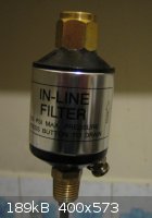
I haven't used the pump much, but it seems to be doing 'something'. There's a valve, lower right in snap, to drain off captured oil. That's about it.
I mounted it on the copper outlet tube with a section of plastic hose for gasket.
The pump is very quiet. I forgot to power it down and it was on for around 40 mins or so just inhaling away. After that, depressing the valve on the
filter gave a little gush of oil. So, yes, it is doing something.
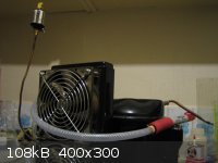
In anticipation of longer runs I've upgraded the cooling system. From latex bondage spirals (earlier snap) to a cooling unit scarfed from a computer.
It's like an auto radiator with a pair of fans; needs cold water and 12VDC. Also seems to work and to do 'something'. Sucks down the temperature on
the pump housing.
I'm expecting good things from this.
|
|
|
aonomus
Hazard to Others
Posts: 361
Registered: 18-10-2009
Location: Toronto, Canada
Member Is Offline
Mood: Refluxing
|
|
A revisit after a month or 2 of hard usage: multiple vacuum distillations of solvents, vacuum filtrations (with controlled air leak to reduce pressure
differential) with corrosive filtrate (read: HCl!!!) and other various bits of abuse (a fair amount of solvent and water being pulled through but
dried by allowing the temperature to rise while drawing air straight through the pump) I have something to report.
The pump still lives on, after multiple oil changes to standard drug store mineral oil, I get 24inHg as the strongest vacuum possible at this moment
in time. Perhaps corrosive vapors caused damage, however I suspect more of the problem has to do with the natural vapor pressure of hot mineral oil
itself. It already vaporizes readily at about 120degC under atmospheric pressure, so at 40-50degC I would suspect a fair bit of it is lost as vapor
and is reducing the maximum attainable vacuum.
Other than the drop in maximum attainable vacuum, the pump is a little harder to start, taking an extra second or 2 to really start turning once I hit
the start winding, and it takes a few minutes on 'low' before the start winding can be turned on again briefly to push it into full power. Keeping a
fan blowing across the casing does help with the heat, though a cold bath may help the situation more.
Edit: a thought that came in mind was that perhaps the 24inHg measurement may be inaccurate. Considering that the pressure gauge I have is an Omega,
-30inHg to 100psi gauge, perhaps its accuracy is to be questioned at the low end of its range. I will order a full scale 0-30inHg gauge next chance I
get.
[Edited on 6-12-2010 by aonomus]
|
|
|
aonomus
Hazard to Others
Posts: 361
Registered: 18-10-2009
Location: Toronto, Canada
Member Is Offline
Mood: Refluxing
|
|
Apologies for the necro, I got a more accurate vacuum gauge. Actual vacuum is 28.5inHg. Pump still going strong, but starting is becoming harder.
|
|
|
IrC
International Hazard
Posts: 2710
Registered: 7-3-2005
Location: Eureka
Member Is Offline
Mood: Discovering
|
|
I think you guys are wasting your time using these pumps unless you are looking for a distillation setup or a roughing pump. 40 mb = 30,000 microns if
I did the math right. For a decent laser you need to get down to say 60 microns or lower. The link below is only a hundred bucks, 126 with shipping,
and gets down to 37.5 microns. Assuming you blow half this trying to get a vacuum system built out of a refrigerator you are not gaining much. Double
that amount and you have a brand new pump which will do very well. Myself I look at the pumps you are using as roughing pumps at best. I used to use
one for this reason just to save on my expensive pumps, never turning them on until the roughing pump has gone as far as it can. Later I found a
surplus rotary in need of a rebuild so it only gets to 150 or so microns as my roughing pump, replacing my old refrigeration compressor pump. Just
seems to me the pump below is a better use of your time.
http://cgi.ebay.com/3CFM-REFRIGERATION-AIR-CONDITIONING-VACU...
I have a question for someone. What kind of glue sticks to plexiglass and seals down to say one micron. My vacuum station gets down to near 60
microns, and my big pump takes it down to just under a micron. I posted pics of the station elsewhere. I took it out of storage, meaning to build my
own CO2 laser for years but never getting around to it until recently. Anyway I was down to 11 microns and heard a crack, the Plexiglas is half inch
thick but I fear it is gone now. Imagine a 14 inch square surface with inlet in center. Glued to the Plexiglas surface is a neoprene disc which the
bell jar sits on. My fear was after seeing the crack that while the bell could hold a micron, the Plexiglas could suddenly implode upwards into the
bell jar. So I set out to rebuild the entire top deciding to tear it apart and add a metal plate under a new sheet of 1 inch Plexiglas to eliminate
the possibility of implosion. The worst that could happen now is the metal starts to pull up cracking the Plexiglas surface, yes wrecking the top
forcing another rebuild but eliminating the implosion risk.
When I first built the station 60 microns was the best I could do, by design I had already added a port to connect a better pump but until recently 60
microns was my limit. I know the Plexiglas - epoxy - neoprene works as I have pumped the bell jar to 60 microns, shut the valve and seen it hold there
all day, implying the epoxy was sealing to the Plexiglas well.
I used epoxy to glue the disc to the Plexiglas surface. What appears to be happening now is around 11 microns the disc starts to swell upward and
leaking begins. As far as I can tell the epoxy does not 'wet' the Plexiglas. Maybe 'wet' is a poor term, by this I mean the air seems to be leaking
between the hard epoxy and the Plexiglas surface. The epoxy is rock solid and firmly stuck to the Plexiglas, yet this is the only route I can find for
air to leak in. I would have thought the interface between epoxy and Plexiglas would be thin to a very microscopic degree yet it appears air is
actually finding it's way under the epoxy. So my question is, considering out gassing and other important parameters, what type of glue does anyone
think would be good to glue the disc to the Plexiglas surface?
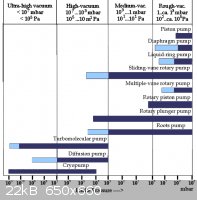
If you study the link below you will see the piston pump is the poorest vacuum of any on the chart.
http://www.highvacpumps.com/engineering/pressure.html
As I hate reading these pages to see useless dead links I will swipe their image and leave it here, just in case the link ever goes dead.
[Edited on 12-19-2010 by IrC]
"Science is the belief in the ignorance of the experts" Richard Feynman
|
|
|
aonomus
Hazard to Others
Posts: 361
Registered: 18-10-2009
Location: Toronto, Canada
Member Is Offline
Mood: Refluxing
|
|
I would argue the point that these setups are 'useless'. These are good for a roughing pump and/or distillation/convenience vacuum filtration pump
there is nothing as cheap and sacrificial. Not everyone has access to cheap pumps from Harbor Freight either. I'd agree that a $75-100 rotary from
Harbor Freight is essentially sacrificial, but if you can't get your hands on one....
For physics experiments however, I agree that these are mostly useless.
Regarding your cracked plexiglass: A thought comes to mind. Pull a *light* vacuum and drip DCM into the crack, allowing the vacuum to suck it in. Let
it work its way in and then leave it to dry, the solvent weld will be better than nothing.
I think that if anything, the distortion in the plexiglass disc is causing your leaks. Perhaps if your plexiglass is clear underneeth (ie: no steel
backing plate), you could drip water into any possible spots where leaks could be occuring and let the liquid show you where leaks occur visually.
|
|
|
IrC
International Hazard
Posts: 2710
Registered: 7-3-2005
Location: Eureka
Member Is Offline
Mood: Discovering
|
|
| Quote: Originally posted by aonomus | I would argue the point that these setups are 'useless'. These are good for a roughing pump and/or distillation/convenience vacuum filtration pump
there is nothing as cheap and sacrificial. Not everyone has access to cheap pumps from Harbor Freight either. I'd agree that a $75-100 rotary from
Harbor Freight is essentially sacrificial, but if you can't get your hands on one....
For physics experiments however, I agree that these are mostly useless.
Regarding your cracked plexiglass: A thought comes to mind. Pull a *light* vacuum and drip DCM into the crack, allowing the vacuum to suck it in. Let
it work its way in and then leave it to dry, the solvent weld will be better than nothing.
I think that if anything, the distortion in the plexiglass disc is causing your leaks. Perhaps if your plexiglass is clear underneeth (ie: no steel
backing plate), you could drip water into any possible spots where leaks could be occuring and let the liquid show you where leaks occur visually.
|
No argument, this is precisely what I said in my first line.
"unless you are looking for a distillation setup or a roughing pump"
If 20" Hg is good enough Gast pumps come to mind. They will run 24/7 no problem. Around $200 everywhere I looked online but I see these in the $10 or
$20 range used - good all the time. Have a half dozen of them but the only decent use I have is when I built my vacuum desoldering station.
I agree for my physics madsci they just were not good enough. Anyone wishing to get a good enough vacuum for even a simple glow discharge will be
wanting. In the early 60's I did the refer thing out of necessity and/or poverty but they are messy and like to burn up with long use. Bad design for
what we do since most designs to circulate the oil with the freon, at least the ones decades ago did. Never looked at any newer refrigerators for this
use since I long ago gave up and bought a good pump, able to get down in the 65 micron range.
The disc is not Plexiglas it is the neoprene gasket glued to the surface of a new sheet of Plexiglas. I am wondering if the crap from wallmart is too
blame. Did the formula for cheap Chinese epoxy change? When I first built my vacuum station I bought epoxy from Ace hardware. For this new job I
bought a few tubes of epoxy from wallmart. In the last 2 days I cleaned it up and re glued a new gasket down. After over 24 hours to cure it did the
same damn thing. Air comes in under the gasket and lifts it (watching through the bell jar) pulling the epoxy from the surface. This crap never was an
issue even once when I built it years ago. The epoxy is the problem. So I ask again, any ideas on glue?
Today I tried using a ring shaped gasket to eliminate the center portion lifting up. Better until around 200 microns then leaking between the
Plexiglas and gasket occurs, this time using grey epoxy from Home Depot. Seems the surface of the Plexiglas is so smooth nothing sticks well enough.
This is perplexing as it looks no different than the old top except the old one is cracked now. I guess I am off to find a better material but
Plexiglass was easy to work. Would be harder to drill holes for vacuum and electrodes if I used a slab of marble and metal I shy away from as it is a
real pain to run electrodes through it running in the hundred KV range. Ceramic standoffs take up too much room and are damn near impossible to seal.
Also ozone from corona was a pain and lowered voltages which is why I went to Plexiglas years ago.
I miss the large insulated top but I am trending to a 14" square sheet of 1/8" stainless if I can find a sheet cheap enough.
[Edited on 12-20-2010 by IrC]
"Science is the belief in the ignorance of the experts" Richard Feynman
|
|
|
aonomus
Hazard to Others
Posts: 361
Registered: 18-10-2009
Location: Toronto, Canada
Member Is Offline
Mood: Refluxing
|
|
A more flexible cement comes to mind like rubber cement. Perhaps the distortion in the acrylic plate is causing cracking. Perhaps construction
adhesive?
|
|
|
IrC
International Hazard
Posts: 2710
Registered: 7-3-2005
Location: Eureka
Member Is Offline
Mood: Discovering
|
|
Sounds worth investigating. One thing is out gassing. Where would one find a chart showing how well various adhesives do in this area I wonder.
Before anyone says UTFSE I have. Seems this is not a parameter much published when it comes to different glues.
I should clarify, pages like this: http://techbriefs.firstlightera.com/EN/Microsites/1/Master+B... are easy to find. Which is why I chose epoxy the first time. What is hard to
find are specs on out gassing for glues I can buy locally. The sheet of Plexiglas the first time came from a tank for etching circuit boards. The
sheet in question now is new. What I am wondering is if the old sheet had some difference in the surface which allowed epoxy to grip the surface
better than a new one. Outside of scratches over the years the two do not appear different.
[Edited on 12-20-2010 by IrC]
"Science is the belief in the ignorance of the experts" Richard Feynman
|
|
|
aonomus
Hazard to Others
Posts: 361
Registered: 18-10-2009
Location: Toronto, Canada
Member Is Offline
Mood: Refluxing
|
|
Outgassing studies aren't typically performed for epoxies or other compounds if they aren't intended for highvac use. Aerospace and other applications
that are offgassing sensitive probably run long term studies at various pressures and temperatures to try to determine the limits of their material,
then advertise those as a selling point (ie: performance X at price point Y).
Out of curiosity, why neoprene specifically? Could other materials like a rubber sheet be used? Forgive me if I don't know much about high vacuum
materials, I normally don't encounter them at all.
|
|
|
IrC
International Hazard
Posts: 2710
Registered: 7-3-2005
Location: Eureka
Member Is Offline
Mood: Discovering
|
|
I don't know. I used what I could find or salvage cheap. The one place I asked for a price wanted $90 for a disc 9" Diam by 7/16" thick. Everywhere
else I browse seems just as bad in terms of cost. I need to find a big sheet from somewhere they print magazines. Not sure it's composition but that
stuff is tough as hell. Neoprene is all I could find cheap. Not as tough and smooth as the first build using an old sheet from a friend who ran a
press for Arizona Outdoor magazine.
"Science is the belief in the ignorance of the experts" Richard Feynman
|
|
|
Contrabasso
Hazard to Others
Posts: 277
Registered: 2-4-2008
Member Is Offline
Mood: No Mood
|
|
Looking at a fridge pump as a PRESSURE pump, has anyone any real world experience. I have a task that needs 100psi in very little quantity. Quieter
would be better so not an ordinary paint spray compressor please
|
|
|
IrC
International Hazard
Posts: 2710
Registered: 7-3-2005
Location: Eureka
Member Is Offline
Mood: Discovering
|
|
Fridge pump will give 100 PSI no problem. What works very well at either end is a car AC pump on an electric motor. I mounted an extra AC pump on a
truck with a pressure switch set to open at 120 PSI to deactivate the compressor magnetic clutch from the 13.8 volt system. Fed a tank under the floor
mounted to the chassis, which had a 200 PSI blow off valve (as I always have a backup) leading to an air chuck on an air hose. Great flat fixing tool.
Would have been a great vacuum pump if I needed it. In my mobile air setup I had a filter on the vacuum intake to protect the compressor.
Hey you reminded me A, I had a near the radiator mounted dryer from a car AC between the pump and filter. Had forgotten that as it was the 70's at the
time. At least I remembered to do that at the time. No trouble starting it with the engine running but you have a good point about starting the fridge
pump against high back pressure. Would not be an issue if he could find a refrigeration compressor in good shape built in the early 1960's.
[Edited on 1-4-2011 by IrC]
"Science is the belief in the ignorance of the experts" Richard Feynman
|
|
|
aonomus
Hazard to Others
Posts: 361
Registered: 18-10-2009
Location: Toronto, Canada
Member Is Offline
Mood: Refluxing
|
|
You can use a reciprocating compressor from a small fridge as your compressor which would give 100psi easily.
I would recommend putting both an air filter and drier on the compressor intake to protect it from rusting or wear. Additionally the pump would be
unable to start under pressure most likely, so you would only be able to charge up your air tank until it dropped below a certain level where the
resistance provided by the air backpressure is low enough to be overcome by the motor.
|
|
|
peach
Bon Vivant
Posts: 1428
Registered: 14-11-2008
Member Is Offline
Mood: No Mood
|
|
| Quote: Originally posted by Contrabasso | | Looking at a fridge pump as a PRESSURE pump, has anyone any real world experience. I have a task that needs 100psi in very little quantity. Quieter
would be better so not an ordinary paint spray compressor please |
I have some news that'll make you wet your pants.
I attached the gauge from my oxygen regulator to the output of one (I'd hard soldered a suitable fitting on there) and it was reading 700-800psi.
Please be well aware of how dangerous this is. Mr Piranha manicure here was hiding behind a brick wall, inside the house.
There is no way I'd stand right beside a first attempt at it put together so messy, that amount of pressure needs more care - I was just checking it,
not trying to use it.
I HAVE used them to power airbrushes. They work brilliantly for that.
And I know a number of guys have attached them to cylinder to go up to 100psi.
They are orders of magnitude quieter than a typical compressor, which you'll have to shout over.
I have opened a number of used laboratory vacuum pumps. So far, the pump head has looked like a bit of iron you'd find on a beach, as it's not
submerged in the oil bath and, while it's sitting doing nothing, the oil that sprays around inside drips back off the head.
INSIDE the pump head, they're still super clean, because there's a film of oil wiped all over it.
The fridge pumps I've opened, even ones I've put water vapour and steam through, have shown no signs of rust. Inside the head it's self, as with the
lab pumps, it's always been spotless. Must be something different about the metal they're casting them with.
But a filter, as anomalous suggests, might be a good idea since it can be as simple as a test tube with some drying agent in it.
I still have the gauge hanging off the side of that pump in the garage. If I can dig through the plumbing fittings, paint, sanding belts and countless
other bits of junk I've been using these last few months, I will try to make a quick video for you.
I did make one before, but had to format the computer, and lost hundreds of photos and video clips.
[Edited on 4-1-2011 by peach]
|
|
|
aonomus
Hazard to Others
Posts: 361
Registered: 18-10-2009
Location: Toronto, Canada
Member Is Offline
Mood: Refluxing
|
|
Well, I'd go a significant step further than a test tube with dessicant. I'd load a large clear tube with 2 plugs of color indicating drierite at each
end with a large plug of drierite (plain) in the middle so you know when you have to regenerate. After the drier I would add a fine particle filter so
that any dust can't get sucked into the filter. Also of note: weigh the 'dry' mass of the drying tube since a known quantity of drying agent can
handle a certain weight in water its theoretical limit can be determined. The practical limit is probably a good deal less, but its still a reference
point as to when you need to start looking out for water.
Back on the rotary vane compressor front, I've noticed that each time I've started the pump it gets harder and harder to do, though I suspect it is
because I haven't changed the oil in a long, long time. I'll have to empty out the whole pump and flush it out with some oil to see whether the
starting improves. I doubt the inside of the pump head is actually rusted, more likely some of the bearings are starting to get seized up with all
sorts of organic crap floating in the oil.
|
|
|
1281371269
Hazard to Others
Posts: 312
Registered: 15-5-2009
Member Is Offline
|
|
I recently bought a fridge compressor from eBay (I know I could have got one for free, but this was £2.40 brand new). I plan to use it from time to
time for filtrations and perhaps reduced pressure distillations, if it has the oomph.
I've done some research online, watched a number of of the videos in this thread and read through some posts, all of which has been very helpful.
However, I'm having trouble with something 100x more basic than most of what has been discussed - how do I actually wire it up?
http://chisko.com/prodotto-146273/COMPRESSORE-perfor-R600a-G... - the most detailed information on the pump I can find (basically what it says is
that it's a 1/10HP pump for use with R600a refrigerant)
Here's a picture of the pump:
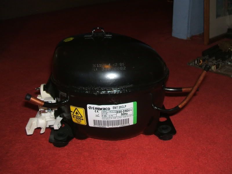
Don't know why, but I find it extremely aesthetically pleasing. Probably the smooth black egg-like shape
Here's a picture of the electrical connections:
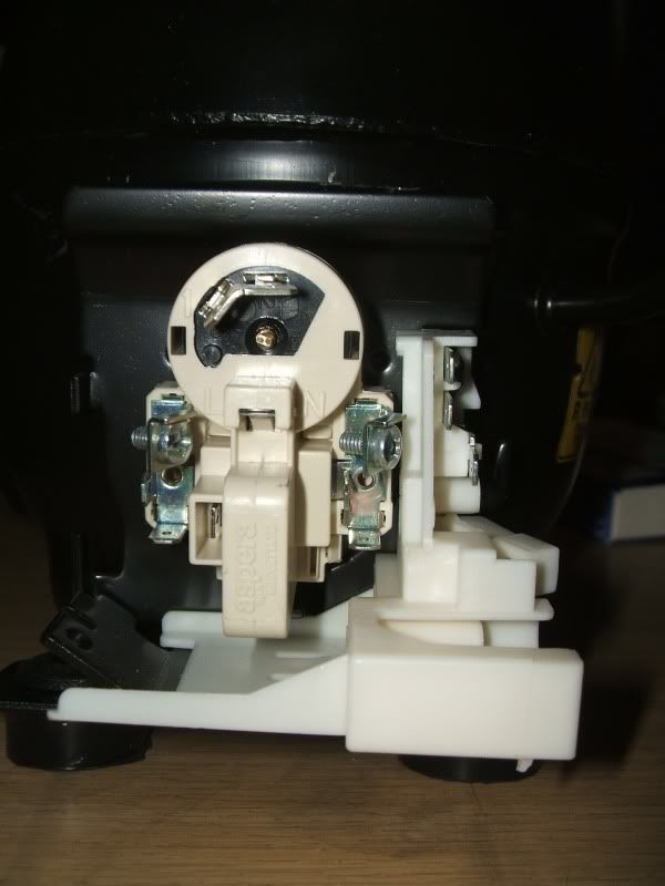
So my questions are:
Can I just wire it up to a 230v mains outlet? (The label on the side suggests that I can, but I want to double check)
If yes, where do I attach each wire?
If no, what other bits and bobs do I need to get it going?
A couple of other things:
The 'service' outlet - should I just ignore it?
Do I need a manometer?
How vital is an air bleed?
Thanks for the help,
Mossy.
[Edited on 5-2-2011 by Mossydie]
|
|
|
1281371269
Hazard to Others
Posts: 312
Registered: 15-5-2009
Member Is Offline
|
|
Just found this:
http://www.embraco.com.br/portugue/produtos/informativos_pdf...
If you scroll down to the bottom it has various electrical diagrams.
Help is really appreciated - I'm way out of my depth here.
|
|
|
entropy51
Gone, but not forgotten
Posts: 1612
Registered: 30-5-2009
Member Is Offline
Mood: Fissile
|
|
I was able to use the very, very old compressor I
have by just:
1. Connecting the house mains current to the two proper terminals and
2. Momentarily connecting a starting capacitor across the two proper terminals with a pushbutton switch. The switch is depressed until the unit
starts (a second or two) and then released.
If your compressor is this simple you basically just have to identify the proper terminals and find a start capacitor of the proper rating
(microfarads and voltage). The tables in that pdf should help with this. Good luck!
|
|
|
peach
Bon Vivant
Posts: 1428
Registered: 14-11-2008
Member Is Offline
Mood: No Mood
|
|
USE A LOCAL CIRCUIT BREAKER!
{edit}I have also just noticed a mistake I am making in this post. That is not a starting relay, it's the overload switch
Awww..... it still has the caps on from the factory, the innocence! 
£2.30 isn't bad at all. If you can get one that cheap, may as well save yourself the hassle of possibly get bitched at by the bin guys and ending up
with a dead one.
I'll post some photos of the ones I have so you can compare yours with mine, it's always nice (to me) to know what's happening INSIDE a black box or
WHY something works. In fact, I like it so much, I'll often break things in working it out, or otherwise retard my life (e.g. revising) in wanting to
understand it rather than just memorise it.
The compressors tend to have lots of connections on them because all the wiring in the fridge, for the light, door switch, temperature control and so
on is done from the side of the compressor; lots of the connections are simply repeats of other ones, another point to connect the mains powered bulb
to for example. The guys wiring the fridges up at the factory have all the wiring terminated in push on spade connections, so they can jam them onto
the connections as yet another fridge goes past.
I suspect the layout for this one is as follows;
Brown is live, the fused wire from the plug.
Blue is the neutral. Those visible strips of metal in the circles are all two pieces, but each piece is one strip, so all
the connections on that strip will be for live or neutral respectively.
That alone should be enough to get the pump going, if you wire a fused plug to those two. The compressors are low wattage, so use a low value fuse
like a 3 amp. That way, the fuse will burn out before the compressor if it ever gets stuck for some reason. It also means you won't roast yourself so
badly if you get stuck to it, in a bad way.
This isn't necessary, but for the sake of understanding what's likely going on, I'll add it anyway - others might find it useful working out
different layouts
The bit circled in green and yellow, I think may be the earthing points. Obviously, the can of the compressor is one big
metal lump. There are also circuits inside the fridge that are at mains voltage when it's working normally, and damp, and metal tubing people can poke
knives into when defrosting. You can check if this bit is the earthing block, as it will feature some form of direct metal to metal connection with
the case of the compressor.
I have put two red arrows points to those spare push on terminals. I think those are likely connected to the strips beside
them, but the connection is hidden under the plastic. If you have a multimeter, or can borrow one, try setting it to Ohms and touching one probe
against the terminal and the other against the strip beside it. For example, use one probe on arrow 1, and the other on the bit circled in brown. If
it reads a low value (probably zero), it's all the same piece of metal. But there are TWO separate pieces in total, one for the live
and the other for neutral - with a 230Vac difference between them. If you put your finger between the bit circled in blue and the bit in brown, you'll
get a nasty shock.
The bit in orange is pointing to the starting relay. This is basically THE ONLY electronics needed to power the pump up.
The relay is inside that little black circle with the adjusting screw on it. Inside, it's two bits of sprung metal. The pump needs a push to get it
running. There is an extra winding on the motor coil inside. When power is first applied, that coil runs to get the pump going. Then the relay
switches it off. It happens so extremely quickly, the start coil only needs to give the little piston a flick - like starting a prop plane engine.
Don't mess around with the adjusting screw or try to take the black circle apart, it'll probably die in the process, and finding replacements is
tricky enough you may as well dump the compressor and get a new one. The relays are basically all the same thing for every compressor, and even
feature similar pins, but they're moulded into different shapes and won't physically fit into the different mouldings on other brands.
You can actually pull this whole white assembly off, and the black circle, without breaking the compressor. Just underneath that black circle, there
are three pins sticking out the side of the casing - they look like tac nails. They're the ends of the wires on the motor inside, and they're welded
or brazed to the can from the inside, to make the seal gas tight. The starting relay, and this white bit full of other connections, just pushes onto
those. There are three pins because two of them are for the motor and the third is for the extra starting winding, which the relay flicks on and then
off when the compressor is plugged in.
The purple bit looks like a bridge connection for something to do with the relay. If it's one strip of metal with no
connections on it, ignore it.
The ENTIRE area in teal is a serious shock hazard, as there are exposed mains connections and most of the
compressor is metallic. You need to put the cover back on, insulate some other way or be extremely careful when moving it. Given how much exposed
metal there is, and what you'll be using it for, it is best to insulate it, as you can easily spill or splash things on it. Also make sure the
connections are either pushed on so hard they take a lot of effort to get back off, or solder them on. I have had some of these where the connections
where loose enough they'd fall off. The main risk there isn't sparks and explosions, it's you thinking the power has gone off and poking around with
it, only for it to zap you.
When I first took one out of a fridge myself, alone and in my early teens, I didn't bother a circuit breaker or putting the cover back on. The pump
went silent, as normal, once it'd pulled a vacuum in something. I had left it going for hours and forgotten it was on, then picked it up. It wasn't
until I had a firm gasp of it with both hands, that one of my fingers touched the exposed mains connection, and I took a serious hit of joo-joo juice
through the chest (as my other hand was on the can). I wouldn't want someone else to repeat that.
GIMP, unlike photoshop, is free.

Here's an example of a pump minus the extra connections. The only thing left is the starting relay (contactor), the live and the neutral.
There should really be an earth on there too. Note that the relay is exactly the same thing, and in the same place as yours, but a different shape.
This is also the pump that the factory fittings fall off if I so much as turn the casing; they need crimping on better than that.


The actual pump it's self, which sits on springs inside the casing. The motor is fairly big, and VERY quiet, so you could score a decent motor
from one of these for another project if you like. I believe it is a brushless induction motor. Brushless means that there are no points for sparks to
come from. This is important as a lot of refrigerants are highly flammable gases, like pentane. Brushes also wear down, so not having them
significantly increases the motor's need for maintenance to essentially zero. It will almost certainly run without the starting relay if it's not
connected to the piston (which is where all the friction is). The motor's spindle has only one bearing surface, at the top, and I suspect it's simply
a well bored, possibly honed, bit in the cast iron, not an actual ball bearing race. Despite this, the spindle spins with almost no force once the
piston is removed. The spindle is hollow, and dips down into the oil sitting beneath the motor in the casing. As it spins, oil is pulled up through
it's centre and bleeds out through the top to oil the bearing surface, cam and piston; kind of how it does in a car if that makes it easier to
understand.
The clunking you hear when shaking a fridge pump is this bit wobbling around inside.

This is the top of the motor. The entire pump is made up of very few cast iron, or possibly steel, components. In fact, there is very little
inside there bar iron / steel and the enammeled magnet wire. At the top of the spindle is a little eccentric cam. This drives the equally tiny piston
back and forth; it's about the size of a Rolo (for the UK guys ). The square
block over the piston, with the cam on it, is where the oil comes up to lubricate it all. The oil doesn't spray out like a hose jet, it bleeds
through.
The two dome shaped things towards the front are the points at which the compressed gas exits the piston chamber, via a length of thin copper tube
brazed into the cap. I have been messing around with this one, that white PTFE tape is not usually there. Instead, the caps are sealed with little
rings of what looks like resin soaked paper. I expect they are put on wet, and dry once tightened to seal the compressor up.
I am unsure why there are two domes. There has been two in every compressor I've opened, yet one of them is never actually connected to any tubing.
I can only assume there is a reason for it being there, because having the production line people screwing an extra cap on wastes time. And time is
money. It may be used in different models, and this is a standard casting.

The gas returning from a fridge usually re-enters the pump head through a plastic scoop / nozzle on the front of the pump head. I've been
gluing bits of copper tubing into the hole to try something with this one. The scoop is normally a piece of white plastic and looks like snorkel of
some description; I suspect they're all made from polyethylene. It's worth noting that, when you use these as vacuum pumps, you will be connecting the
vacuum hose to the connection where the gas usually comes back in. This is NEVER actually connected directly to the pump head it's self. The returning
gas is usually used to help cool the motor, so it swirls around inside the casing before going back up the snorkel. This is not particularly
important. You could argueably make the compressor even less prone to corrosion and explosions by making the connection directly, but I have run so
many solvens through these I can't remember them all, and they're designed to have highly flammable things in them; things which are used as solvents
in labs. It also doesn't matter so much if you plan to connect two in series, to increase the vacuum. It DOES matter if you plan to try putting two in
series to create a high pressure compressor, as you will be pressurising the second compressors can to the outlet pressure of the first, which is over
500psi. BAD things may happen on doing that. With one compressor alone, it is a lot less dangerous as, if the compressor head pops, the flying bits
will be caught by the metal casing, and the casing will be open to atmospheric pressure, so it can discharge pressure buildup. Also worth thinking
about is that gas being compressed will be travelling over oil, which can ignite or explode in the presence of compressed oxygen.
Whilst the casings are thick steel, welded shut, their thickness may vary from model to model. Some pumps also feature dents in the casing for fitting
a drip pan to the top, where condensation from inside the fridge collects and then evaporates back into the atmosphere over the warmth of the running
pump. These varying thicknesses, none uniform shape and dents mean that the pressure holding capacity of each pump may be vastly different, adding
another danger to running them in series for high pressure use.
I have not seen any signs of corrosion in these pumps, yet, that come ANYWHERE close to the levels I've seen inside used laboratory pumps. I suspect
the lab pumps are suffering not just from moisture, but more likely the reactive gases being pulled through them. Either way, provided the corrosion
is only on the outside of the pump head (which it universally is in my experience) it's not much of a problem. The outsides of the pump head can rust
because the oil film drips back off them when the pump is switched off, whereas the chambers stay oiled. The outside is also more open to the
atmosphere. And I suspect even people like Edwards are using the lowest grades of cast iron they can manage.
The 'magic' of the compressor happens just behind the plate that is bolted on at the front. There are thin strips of sprung metal that act as valves.
When the piston moves forward, one closes and the other opens. When it moves back, vice versa. Without them, the compressor would do very little.
Again, the plate at the front appears to be bonded to the rest of the pump using some form of phenolic paper, which has been applied wet with glue. As
it needs scraping off when the bolts are undone.
You can reseal the parts with vacuum grease if you take one to bits, as the paper seal will be ruined when it's forced open. There are actually very
few points for the compressor to leak through.
One point someone has raised is that the valves are a likely candidate for what limits the compression ratio of the pump, that they don't seal
perfectly. Indeed, there is no rubber seal in there, it's an oil film. I have tried replacing the oil with high vacuum grease, and it seemed to help.
So I am VERY interested to know what the pump might achieve if one added an extra, better quality, one way valve to the line on the outside. Perhaps
this could give us our 1mBar pressure without having to open them up.
I will add it to the TO DO list. Just below, find a valve and afford a valve.

Here are the pins the motor makes it's connection to the outside world through. There is also an earth connection fixed directly to the casing
at the same point on this one.

Here's another example. Remember that all three of those pins connect to the motor windings, none of the PINS are an earth.

This is the front of the pump with the plate and valves removed. You can see the remains of the washer I was talking about.

The smaller copper tube is the higher pressure outlet, and it is connected directly to the pump via one of those domes on the top, and brazed
into place.
There is a wider bore copper tube there and there will always be two of these that don't connect to anything on the inside. This is so the factory can
fill the pump with oil more easily. By having two wide tubes sticking into the side, there is no back pressure when they pump the oil in.
They then crimp and brazed one of them shut, as it's no longer needed - you will see it sticking out the side of pumps in the backs of fridges.
You can connect your vacuum line to either of these, as they both enter the pump in the same manner, through the casing and then nothing more.
However, one of them will be connected to the rest of the fridge, and you'll need to cut through that to get the pump out, so you may as well use that
one and leave the crimped one alone.
You can tell which line is which, our of the two connected, without opening the pump and before it is taken out, as the high pressure one will usually
have an expansion bulb on it (which looks like a little CO2 vessel used in nitrous oxide and CO2 drinks fizzers).
Once it's out, you can tell just by switching the thing on and blocking one of them with your finger.
You can operate the pump with both the wider lines open to the atmosphere. You can drill endless holes in the casing if you like. But it WON'T produce
a vacuum until all but one of them is blocked up again.
You can go even further, as I did above, and cut the casing open, provided you make a direct connect for the vacuum line to the pump head, as the
casing is not longer providing the seal.
There are reasons for which you may want to cut the crimped tube open again. For example, to drain out the oil. There is no immediate need to do this,
they work fine as they are.

This is the other side of the pins. They are brazed or welded to the casing, as all the connections are. The motor's leads connect here, and
the relay sits on the other side.
There is another of those wider opening tubes, the line IS NOT connected to anything inside the pump and it is where the gas returns; the gas simply
flows into the casing and up the snorkel on the pump head.
The amount of oil in there is roughly what you see in the photo, it's a about 150 to 250mls from memory, a puddle at the bottom.
Why drain the oil? If you, like I have, dump a lot of solvent through the pump, it may reduce the maximum vacuum it can achieve for a while, as the
solvent will spend a long time evaporating off again. You can sort that by simply blocking the vacuum intake and leaving the pump running.
A more interesting possibility is, I have tried swapping the original oil for genuine vacuum pump oil, and seen the pressure decrease. It is likely
the manufacturers are using higher vapour pressure oil because it's runnier, produces less resistance and flows into the gaps better, and because they
don't need anything better.
As with the extra external valve, swapping the oil for genuine pump oil may be an easy modification that could drive these pumps down to the seriously
handy level.
And again, I will attempt to investigate this with a more precise gauge. I have already tried it once. The only concern I have is that the pump does
seem to run warmer, and sticking a computer fan over the top may become a good idea with thicker oils.
I have also tried cutting the cans open and coating the entire pump head in thick grease. It does work to reduce the pressure, but it is FAR too much
effort and the grease needs continually putting back, by hand. So I rule that out as a useful, easy idea.

This is one of the dome caps, with the high pressure line still brazed on. You will sometimes find an expansion bulb / mist filter INSIDE the
pump and connected to this line. I have shaken a few expansion bulbs and heard the rattling of what sounds like fine grains, which is why I suspect
they are also functioning as mist filters in the newer models. And it may be an idea to leave the external expansion bulbs on the pump when you cut it
out, for a spare exhaust filter in the deal.

You MUST use a breaker with this kind of thing. I know they usually seem to do sod all, but here you have large lumps of exposed metal,
exposed mains connections, possibly loose connections, conductive salts and solutions around and you are likely not 100% sure of the wiring. The
chances for a shock are very high.
Forgetting the shock problem, the breaker will also act to compensate for some of your mistakes. If you manage to wire the pump incorrectly, either
this breaker or the mains breaker will flip when it detects a residual current or over current fault; which happens faaaaaar faster than a fuse can
manage. You should only really consider fuses as a last line fire defence, as opposed to something that'll rapidly stop faults or shocks.
The response time of circuit breakers, and the mains ring they are feeding, is actually part of the Part P building code. The breaker has to be able
to trip within a set time for a specific circuit or application, which corresponds to a specific quantity of energy being delivered to the person
shorting it on the other end. They get picky enough about this that qualified electricians have to check the ring impedance (not simply it's
resistance) to sign it off as safe.


[Edited on 6-2-2011 by peach]
|
|
|
| Pages:
1
2
3
4
5
6
..
8 |
|


