Sigmatropic
Hazard to Others

Posts: 307
Registered: 29-1-2017
Member Is Offline
Mood: No Mood
|
|
Ika-combimag ret stirring problems
Hello dear sciencemadness folks,
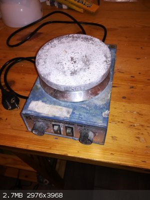
I've got a several decades old Ika-combimag ret stirrer hotplate combo which had heating issues. I've since then resolved that issue by replacing the
corroded thermocouple.
It used to be stirring fine at all speeds but since I opened it a few times to check the heating element and replace the thermocouple, I am now having
issues with the stirring side of things. The stirring now only has two modes, full on or off. From about 1/5 th of the way on the dial (0-1000 rpm, so
about 200 rpm) it goes on full. Given that that's a 50k resistor I guess that happens at about 10k ohm.
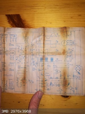
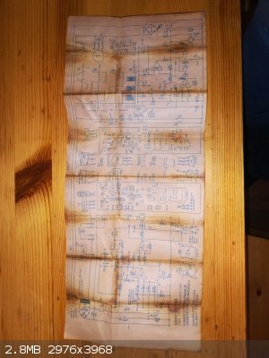
Now I am not an electrical engineer and I am somewhat lost. Luckily, being German made, it had a schematic drawing of all electronic components inside
(see attachment) . Also the circuit board is not miniature so even an amature like me can do some soldering and hopefully fix it.
Can any of you give me some pointers as to what may be faulty or what components I need to check?
Unfortunately I do not own an ossiloscope so those a-d potentials I cannot check, but if that is needed I could probably find someone who can.
Thanks in advance!
[Edited on 19-3-2020 by Sigmatropic]
|
|
|
Sulaiman
International Hazard
Posts: 3558
Registered: 8-2-2015
Location: 3rd rock from the sun
Member Is Offline
|
|
My first suspect is the actual pot.
If you can measure Ohms then test the pot,
if you have an alternative 10k (B=linear) pot then try that,
if not, reverse the connections to the outer two terminals,
if it is a break in the resistive element then the change will occur at exactly the same dial setting, but in reverse.
or
If you do not mind probing with a dmm whilst live ;
measure the voltage from 0v (pin 10) to pot output (pin 11), it should vary linearly from 0v to 3.9v, approximately.
if not the pot then ask again.
... it could be that the optical speed detector has been mis-aligned or is not working,
check that the voltage across C4 increases with increasing motor speed.
[Edited on 20-3-2020 by Sulaiman]
CAUTION : Hobby Chemist, not Professional or even Amateur
|
|
|
Fulmen
International Hazard
Posts: 1693
Registered: 24-9-2005
Member Is Offline
Mood: Bored
|
|
DUDE!
I have an old broken Ikamag ret, it looks identical to your combimag. Could you photograph any schematics and the inside of the unit? Part of the
wiring got pulled apart by accident and I have no clue where they should go anymore.
It also had the same fault you're experiencing, only intermittently. I always suspected the optical reader, but I can't do anything more until I fix
the wiring harness.
We're not banging rocks together here. We know how to put a man back together.
|
|
|
Heptylene
Hazard to Others
Posts: 319
Registered: 22-10-2016
Member Is Offline
Mood: No Mood
|
|
I can't really help much, I like electronics but I don't know enough to do help with repairs myself yet. Since there aren't many components, maybe
just check them all? Or those you can check easily at least. Are there any burn marks? Check the power components for obvious failure signs.
Just for our viewing pleasure, do you have a picture of the actual insides of the hotplate? I took opened my IKA C-MAG HS7 open once just out of
curiosity, and it also uses a photoelectric barrier to control the motor. Nowadays they most definitely don't put the schematic inside though...
|
|
|
Sigmatropic
Hazard to Others
Posts: 307
Registered: 29-1-2017
Member Is Offline
Mood: No Mood
|
|
OK thanks Sulaiman, I will check the potentiometer/variable resistance as soon as I get ahold of my multimeter, which is because of this social lock
down situation, out of my reach. Very helpful edit as soon as I get my multimeter I will read those pins.
So I've took the stirrer plate apart and made pictures. First off I cleaned some grime off of the IR-diode and receiver with some alcohol/cotton ball.
Behavior unchanged, still only an on and an off as to stirring.
Next I decided to check whether there was any IR there by making pictures/foto's with my mobile phone. (red. Mobile phone cameras pick up IR, check it
with your TV remote). There was no IR.
To be continued....
|
|
|
Sigmatropic
Hazard to Others
Posts: 307
Registered: 29-1-2017
Member Is Offline
Mood: No Mood
|
|
Now for the actual insides, first is the stirrer side of things, second (the one with the connections for the thermocouple and heating element
(ceramic plug)) is the heating side of things.
The electrical motor and magnet have been removed for more easy viewing.
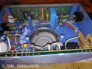 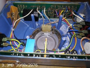
Edit: sorry for making an end on picture, the optical elements are sticking out on the left of the yellow green capacitor/condensator.
[Edited on 20-3-2020 by Sigmatropic]
|
|
|
Fulmen
International Hazard
Posts: 1693
Registered: 24-9-2005
Member Is Offline
Mood: Bored
|
|
Thank you soooooooo much. While the boards are different it has the same basic layout and wiring, so I should be able to rewire it from the pics.
Hope it's something simple on your end, a blown led should be fairly easy to replace.
We're not banging rocks together here. We know how to put a man back together.
|
|
|
Fulmen
International Hazard
Posts: 1693
Registered: 24-9-2005
Member Is Offline
Mood: Bored
|
|
Aw crap. I tried to fix it to see if I could replicate your findings, but it's falling apart between my fingers. First the TC broke (K element?), then
one of the pots broke in half. So I will have to order up some replacement parts first.
To be honest I'm leaning more towards rewiring it with an arduino. The heater and temperature sensor should be a walk in the park, I already have a TC
probe for arduino and I'm waiting for a shipment with a couple of SSR's. But the stirrer is a 3phase 220V motor, what's the best way to control this?
We're not banging rocks together here. We know how to put a man back together.
|
|
|
Sigmatropic
Hazard to Others
Posts: 307
Registered: 29-1-2017
Member Is Offline
Mood: No Mood
|
|
P3 (pin10-pin11) reads 1-44 kOhm, looks like it's good
Whilst live it goes from 0-3.9V, like it should.
Potential across C4 is always 5.9V regardless of motorspeed.
So this points to a faulty optical receiver? Although I don't see IR with my phone the led has conductance in one direction, if it's blown, does it
still work as a diode?
|
|
|
Sulaiman
International Hazard
Posts: 3558
Registered: 8-2-2015
Location: 3rd rock from the sun
Member Is Offline
|
|
Yes
I.R. LEDs have the electrical characteristics of a diode even when light output has fallen to unusable levels.
If you have an old/unused I.R. remote control (TV, VCR, air-con.....) you could use its ir led.
CAUTION : Hobby Chemist, not Professional or even Amateur
|
|
|
Sigmatropic
Hazard to Others
Posts: 307
Registered: 29-1-2017
Member Is Offline
Mood: No Mood
|
|
Okay so today I placed a new IR led, in what I really think is the right way (note), and the stirrer still shows the same problem. IR Receiver maybe?
Does anyone have any other suggestions? Preferably one which entails measuring components until one seems off, not a replace xyz, as that might take
me a quite while. Although considering components are cheap and a stirrer-hot plates are not, Im all open to suggestions.
Note: I read no conductivity with the red pin of the multimeter on R4 and the black pin on one side of the led, while on the other side of the led it
is conductive. switching black and red pins gives me conductivity through out.
[Edited on 13-5-2020 by Sigmatropic]
|
|
|
Fulmen
International Hazard
Posts: 1693
Registered: 24-9-2005
Member Is Offline
Mood: Bored
|
|
Did we cover digital cameras to detect IR? A lot of cameras are sensitive to IR, more than enough to check IR diodes. Another possible problem could
be that copper mirror...
Edit, my bad. On my board the leds are mounted on the main PCB and use mirrors to read the slotted disk, it's not entirely clear from the photos but
your sensor appears to be different.
[Edited on 13-5-20 by Fulmen]
We're not banging rocks together here. We know how to put a man back together.
|
|
|
Mateo_swe
National Hazard
Posts: 505
Registered: 24-8-2019
Location: Within EU
Member Is Offline
|
|
I would clean up the inside, pcbs and components as the unit has signs of chemicals and corrosion inside.
This could be why it isnt working correctly and maybe it looks worse on the pcb undersides.
And i wouldn't be surprised if you find the faulty part while doing the cleanup.
It might be that some components break while doing this due to weakened state by chemical exposure, but if it does, it would probably have failed soon
anyway so replacement is needed.
For example that small IC (IS2) with rust on the legs dont look good and need replacement or at least cleanup. That ic is needed to work correctly for
the stirring to function properly.
But im sure the unit could be fixed if you put some time into it.
|
|
|
Tsjerk
International Hazard
Posts: 3022
Registered: 20-4-2005
Location: Netherlands
Member Is Offline
Mood: Mood
|
|
I have the same, or at least almost the same Ika with the same problem! I do still have warranty on it, I just didn't contact the seller yet. I will
email him and ask what he thinks, he knows these machines by heart.
My first guess was the potentio as well, If the seller thinks the same I will ask him to send me the part.
|
|
|
Sigmatropic
Hazard to Others
Posts: 307
Registered: 29-1-2017
Member Is Offline
Mood: No Mood
|
|
Thanks Mateo_swe, I'll get round to doing that soon. I Must agree with you that IS2 looks particularly bad.
I found this thing under a fume hood and it looked like it had been sitting on top of a puddle of HCl, that is: badly corroded.
Indeed the part that was broken on the heating side of things was the iron part of the thermocouple, rusted through completely. So I wouldn't be all
that surprised if this stirring problem is also caused by corrosion and looking at it that way IS2 is the place to start.
To be continued...
|
|
|
Sigmatropic
Hazard to Others
Posts: 307
Registered: 29-1-2017
Member Is Offline
Mood: No Mood
|
|
So I checked continuity between the legs of IS2 and the bottom of the pcb which gave variable results. When I pulled it out the legs broke, go figure.
I've replaced it with a new one but the problem persists, stirring still is basically an on-off at ~100 rpm on the dial.
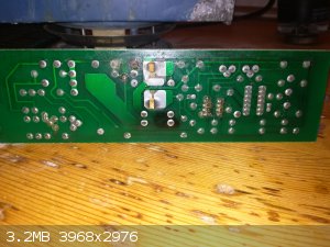
Attached is a picture of the bottom of the stirring pcb. It shows some signs of (over) heating around R2 and R3 and separately around R1 and D1. Based
on the soothing on the pcb backing the big plate from R2 to C1 appears to have gotten warm. This is directly below C7.
C1 gives a reading of 16-17 uF, close to the 10 uF indicated.
C7 reads 0.85 uF, also close to the 1 uF indicated (although it's indicated as 1 uFX/400 v, whatever that may mean). Seems to me C7 is part of the
motor starting circuit and that obviously still works.
R1, R2, R3 and D1 give good readings.
Suggestions are welcome (: .
Edit:
Also rechecked the phototransistor, that works. Perhaps I blew the led when I installed it? It still a diode though so I doubt it.
[Edited on 26-5-2020 by Sigmatropic]
|
|
|
OldNubbins
Hazard to Others
Posts: 136
Registered: 2-2-2017
Location: CA
Member Is Offline
Mood: Comfortably Numb
|
|
R2 and R3 are feeding the phototransistor and one of them appears chipped in the photo, and with the scorching on the board could indicate a failure.
If the signal to chop the voltage is not going to the motor, it makes sense the motor would behave that way as the voltage needs to increase enough
for the cap on the start windings to create the imbalanced magnetic fields for the motor to start turning, then its just full on from there.
The phototransistor initiates the signal to the chopper drive to cut power to the motor at the proper frequency to effectively spin it slower. The
TL062 op-amp near those resistors looks severely corroded. Since it's plugged into a socket, you may be able to remove it and clean up the corrosion
or replace it, they are cheap.
The whole motor speed control can probably be removed and replaced with a triac dimmer switch rated for inductive loads. It's not ideal but works,
I've done it to an old Thermolyne. I used a temp sensor tied to a relay through a microcontroller to control the hotplate. That way all components
were replaceable with off-the-shelf modules.
|
|
|
Tsjerk
International Hazard
Posts: 3022
Registered: 20-4-2005
Location: Netherlands
Member Is Offline
Mood: Mood
|
|
How does this IR sensor thing work? The rotation speed control on my IKA stopped working, I only had no rotation and full speed, and I found out there
should be two rubber things on the rad connected to the motor.
With only one rubber on the rad the speed control didn't work, with two on either side the contol didn't work either. I now have two pieces of tape
about three centimeters apart and the control sort of works, but only partly.
The rubbers are there to calibrate the control, but how does this work?
|
|
|
Tsjerk
International Hazard
Posts: 3022
Registered: 20-4-2005
Location: Netherlands
Member Is Offline
Mood: Mood
|
|
To clarify: There is a ring attached to the motor with slits, above and beneath there are an IR LED and a sensor. Somehow these are involved in
controlling the speed of rotation. There were two rubber calibrators glued to the ring to calibrate the speed, but one of them came loose.
With one of the calibration rubbers the calibration was off and the speed was only slow or full speed. I now have two pieces of duct tape on the ring
(about 3cm apart) so I can control the speed between 0 and about 30%. Above that the stirrer goes 100%. When I put the tape 180 degrees apart speed
goes from 0 to full like there is only one piece.
Does anyone know how to calibrate the stirrer so I can use the full width of the control?
|
|
|
draculic acid69
International Hazard
Posts: 1371
Registered: 2-8-2018
Member Is Offline
|
|
Quote: Originally posted by Fulmen  | Aw crap. I tried to fix it to see if I could replicate your findings, but it's falling apart between my fingers. First the TC broke (K element?), then
one of the pots broke in half. So I will have to order up some replacement parts first.
To be honest I'm leaning more towards rewiring it with an arduino. The heater and temperature sensor should be a walk in the park, I already have a TC
probe for arduino and I'm waiting for a shipment with a couple of SSR's. But the stirrer is a 3phase 220V motor, what's the best way to control this?
|
These are like a mini variac.they work great.if your motor is 220v then they should also control the motor
https://www.ebay.com.au/i/324117300379?chn=ps&norover=1&...
|
|
|
Tsjerk
International Hazard
Posts: 3022
Registered: 20-4-2005
Location: Netherlands
Member Is Offline
Mood: Mood
|
|
Everything is functioning, it is just that the two calibration rubbers from the ring are gone.
|
|
|


