| Pages:
1
2 |
FranzAnton
Harmless

Posts: 45
Registered: 31-3-2020
Location: Austria
Member Is Offline
|
|
High Voltage with High Power for Birkland-Eyde reactor
Hi All, I want to make another attempt of a more powerful BirklandEyde reactor and a main topic is to get a high voltage source with some power in the
kW range. All documents pointed out that AC voltage is helpful an if the frequency is higher it also is contributing to mor NO yield.
So I want to get feedback from your side if it makes sense to modify a cheap inverter welder in the range of 150$.
These types provide 1-2 kW continous power with an improved coolin fan.
How to get high voltages out of it? There must be some efford invested, but not so much than building the whole device from scratch.
The output transfomer of that welder is the important part. I would carefully remove the high current secondary (output) winding and replace it to a
winding with more turns and thinner wire so to get approx. 300-400 volts with high frequency and much lower current. So it's a dangerous voltage, but
will not generate any isolation problems in the welder. This voltage I will bring outside the welder and there have my (tiny) high voltage
transformer.
A good core of a flyback television transformer can take approx. 700Watts at 20 kHz. If I use 2 of them winding the primaries in serie with the
outcomming voltage of the inverter and then transforming it up to lets say 8-10kV or higher if needed.
What I tried already: I did the following with the inverter, opened it up and removed the output rectifier, so that I have around 60V and 25kHz if
there is no load on it. Then I wound my flyback cores with startinf of 10 Windings and reducing it to 2 Windings. I also had for testing reason a
"high voltage" winding with 100 windings. So at least some small sparks should be generated. But it did not work. With 10 windings nothing happened I
I reduced to 2 windings only my flyback cores become warm, but at my high voltage side I can measure some voltage but no power behind.
For the specialists in electronics of you:
I did not usy any air gap in my flyback core.
I did us hf strand wire (because of skin effect)
I am sure the ferrite type can handle up to 40 khz and the losses which warmed them up might rather come from saturation effekts....
So for my next try I will use more windings but also an air gap to avoid saturation.
Do you have other sugesstions what I can do, or ideas why my first try does not work?
The problem is, that I cannot put the high voltage winding direct on the inverter output transformer, because there is not enough place and I also
have isolation problems. So I need to solve this with a forther transformer.
What I also left out (because I was not able to tinker it) is a capacitive adaption network between this 2 transformers. Maybe they have to be coupled
with capacitors.... 
It would be great to get any helpful hints.
|
|
|
Heptylene
Hazard to Others
Posts: 319
Registered: 22-10-2016
Member Is Offline
Mood: No Mood
|
|
Not a specialist, but I've been trying to build switch mode power supplies (SMPS) for a few months so here are my thoughts.
- As far as I can tell an SMPS is designed as a whole, which each part depending on the others. You can't just blindly replace a winding and expect
good results.
- Does the inverter have a feedback loop to regulate the voltage? If you left this unconnected, the controller will push more and more current in the
core, until saturation and damage to/destruction of the primary side switch.
- Also, flyback transformers are not supposed to run unloaded. If they are, the core cannot lose it's magnetisation, it saturates. As you pointed out,
there has to be an air gap, although some core have a distributed air gap (a sort of ferrite foam) in which case no gap is needed between the two core
halves.
- Do you really need to modify it? A regular tig welder makes a few millimeter arc between the tungsten electrode and the workpiece, maybe you could
use that arc directly? The tricky part would be striking the arc. I have seen add-on "HF starter" kits that can strike low voltage high current arcs
easily using a short high voltage burst to first create a conductive plasma.
|
|
|
Twospoons
International Hazard
Posts: 1280
Registered: 26-7-2004
Location: Middle Earth
Member Is Offline
Mood: A trace of hope...
|
|
The short answer is "no".
The long answer is that what you actually want is a high current but with a high voltage start to get the arc going. The reason for this is the arc
behaves as a negative resistance - as the current increases the voltage across it drops.
If you want to use a welder as the power source, then what you are looking for is a TIG welder. These have a high voltage starter to ignite the arc,
then they control current to control the power in the arc.
The other possibility is a controller for a mercury arc lamp - same deal
: HV/HF start then regulated current.
The best place to get help with this is probably https://highvoltageforum.net/index.php
You will find many helpful and experienced people there.
[Edited on 29-4-2020 by Twospoons]
Helicopter: "helico" -> spiral, "pter" -> with wings
|
|
|
WGTR
National Hazard
Posts: 971
Registered: 29-9-2013
Location: Online
Member Is Offline
Mood: Outline
|
|
Quote: Originally posted by FranzAnton  | | Hi All, I want to make another attempt of a more powerful BirklandEyde reactor and a main topic is to get a high voltage source with some power in the
kW range. All documents pointed out that AC voltage is helpful an if the frequency is higher it also is contributing to mor NO yield.
|
From reading your posting history, it looks like your earlier attempts involved using a low power Jacob's Ladder design. I would encourage what we
call "baby steps" on this. Maybe work your way up to higher and higher power with each successful experiment, until you reach the full 1-2kW that you
want to reach.
I abandoned the Birkeland-Eyde reactor design in favor of the Ostwald Process, but I did do quite a bit of experimenting with the Birkeland process
in years past on a smaller scale, and learned a few lessons along the way.
I really enjoy chemistry as a hobby, but I also don't want this hobby to kill me or anyone else trying to replicate my designs. For this reason I
spent some time figuring out how I could easily and reliably initiate a low voltage/high current arc.
My earliest experiments involved manual initiation by shorting annular electrodes with a graphite rod. The arc rotated in a magnetic field created by a ring magnet. This avoided any voltages above
150V, but the arc would often blow itself out and require manual intervention. Plus, the arc rotation wasn't always as stable as I would have liked.
I found a compromise by considering that large quantities of energy are not necessarily required to initiate an electric arc. A very high voltage
pulse from a flyback converter could be used to initiate the arc, with very low average energy required. I used 0.5J as a limit for high voltage
energy storage, as this seemed to be a maximum safe level for healthy individuals in case of accidental shock. An early experiment of this type was show here. The flyback transformer output was placed across the main spark gap via an extra, much longer spark gap. There were essentially
two spark gaps in series, a long one and a short one. 150V was placed across the short spark gap. When the flyback was triggered it would deliver a
high voltage that would jump the large spark gap. This happened so quickly that the inductance of the power supply wires to the 150V supply would
force the energy from the flyback across the smaller spark gap. Once this smaller gap was triggered the output from the flyback converter would
quickly fall. Once it fell below 150V the main power supply would take over and deliver up to 3A DC. The small magnet below the smaller spark gap
would quickly blow out the arc, and then the whole process would repeat once the flyback was triggered again.
The video begins with the high voltage from the flyback being turned on first. You can see it jumping both spark gaps. Then the 150V supply is
turned on, and the larger arc initiates. It is blown out repeatedly into a semi-circular ring by the small magnet underneath the smaller spark gap.
In this way it is possible to control the average power consumption (and apparatus heating) by controlling how often the flyback is re-triggered.
My next idea was a bit more developed. A reactor was built with two copper electrodes, and the magnet was placed under the reactor. Air was very
slowly run through the reactor in the video. After passing through an oxidation chamber, the gasses were run through silica gel. The bubbler merely shows how fast the airflow
was. The silica gel captured practically all of the nitrogen oxides as NO2.
I got to a point where I wanted to measure efficiency of the process, so I put some effort into a newer design, and built a circuit board that housed
all of the necessary parts; the flyback circuitry, the interface between the high and low voltage sections, the filtering components, and a large
inductor that I wound to better control the characteristics of the main arc discharge. The air supply was thoroughly dried over silica gel to remove
all moisture before it was led through the reactor. After spending time in the oxidation chamber the gasses were led through another silica gel
column. This not only adsorbed NO2, but apparently catalyzed the oxidation of all NO as well. I was able to perform several runs, massing
the silica gel before and after each run. Considering the energy input into the system I figured I was getting around 5-7% efficiency or so. Soon
afterwards I lost interest in this design and moved onto other things.
I didn't post any pictures or schematics of the last design. I could do that if there's any interest.
[Edited on 20-04-30 by WGTR]
|
|
|
Twospoons
International Hazard
Posts: 1280
Registered: 26-7-2004
Location: Middle Earth
Member Is Offline
Mood: A trace of hope...
|
|
You might also want to consider a short arc at high pressure.
I had an interesting experience with this when trying to create a small plasma jet, for use in surface treatment.
I had a short arc inside a small chamber with a small exit hole (~1mm dia), fed from a compressor. The power source was a 15kV 30mA neon sign
transformer. These are great for arcs as they are built to be inherently current limited - no bad stuff happens if you short out the secondary.
At room pressure the arc was the normal pale blue spark you'd expect, but as I increased the pressure it became very bright, almost too bright to look
at. I would guess that the increased pressure was raising the arc voltage, and hence the power (current limited transformer, remember?).
An interesting side-effect was that the room air rapidly became unbreathable - and this was a pretty big room with a high ceiling. I've run open air
arcs before and not had this happen.
Conclusion is that the high pressure arc was producing a lot more NO2 than the low pressure one.
I never took this further, as gassing my colleagues was not the goal.
Helicopter: "helico" -> spiral, "pter" -> with wings
|
|
|
FranzAnton
Harmless
Posts: 45
Registered: 31-3-2020
Location: Austria
Member Is Offline
|
|
Dear Helpers!
Thanks a lot of all that detailed answers and the expressive vids!!
My basic goal is to create a reactor design which allows an extreme fast cooling of the reaction gases to increase the NO part in the exhaust gases.
The oxidation and treatment afterwards is a (complex) but different topic.
I also experimented with high current (low voltage) arcs which can be drawn with TIG inverteds and found out that it is extremely difficult to find an
arc designs which allows high cooling rates (mean high NO output). Why? My basic cooling idea (was) is of using turbulent gas streams. So if you have
a low voltage but high current arc it is blown out very fast. If you cannot blow it out because of more amps, it's so hot, that you cannot reach the
needed cooling gradient and the NO output is at it is known from normal Birkland oven designed in the last century.
I studied a lot of master thesis found in the web around this topic and in some points they all agree.
High pressure do not help, more NO is produced in small vakuum arc chambers around 100mbar more then 10%. (But impractical because of the low absolut
mass from NO production)
All depends on the cooling rate and so I focused on the design of the arc chamber. My arc chamber design (or better the design of the arc chamber I
've "stolen in the web) is flat and nearly in the shape of a venturi nozzle.
So I have the need of a very dynamic and powerful high voltage source from the U/I characteristic like an neon transformer, but more powerful because
I have better cooling possibilities.
And so I ended with a inverter design.
TIG invertes are hard to deal with, besause they have to much "intelligence" in case of ignition and arc control built in.
So I focused on the cheap IGBT ones.
Yes they have a current control circuit and Thank God in the primary circuit
(and not like SMPS power supplies which are controlled on the output side)
All I found out on the cheap ones the have a variable adjustable current limit done via PWM of the primary inductor voltage.
So they also can run in idle! With providing the idle voltage around 60V when shortening it the current control reduces the duty cycle to an amount
the transformer and IGBT can stand and the voltage brakes down.
So basically the characteristic of an neon transformer but with less voltage.
That brought me to the idea to transform it up with another ferrite transformer, because of the insulation topic of the high voltage.
Until that point I am quite sure that it will be possible from technical side (only the details about designing the components are the tricky part)
So I have to take care not to saturate my ferrite core, to use a proper material which can stand up to 40kHz without too much losses, to decouple it
from the transformer in the inverter using a right capacitor.
And -maybe- avoid resonance phenomena because this capacitor forms a resonant circuit with the Inverter coil and my auxilary flyback coil.
Finally I was not able (until now) to find a real killer argument why the inverter as a driver of a DIY big ferrite HV transformer does not work.
I learned from you that it is far from easy (and dangerous to deal with high voltages) to design that part, but on this weekend I will give my
inverter a last chance  ... I will do some pics for you that you will get a
better idea of my assembly. ... I will do some pics for you that you will get a
better idea of my assembly.
To summarize the idea of the flat arc reactor is a highly turbulent flat air stream in an arc chamber with expanding electrodes (jacobs ladder) and
the hottes arc zone is running very fast across that turbulences.
But I start ordering the parts for the reactor after I have a reliable power source (and best case that one which is based on a cheap chinese inverter
welder)
I took a lot of information also from highvoltage forum and I saw a lot of real scrappy assemblies that worked fine so I think it's depending more on
the detailed experiance one will have. I was not registered as user there because it also costs a lot of time to give all the helpful people also the
feedbach which they deserve for their hints ..
So I come back hopefully next week with some pics and some further experiances
cheers!
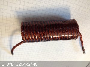
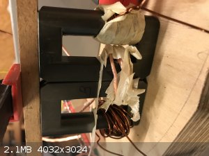
Found a pic of my already wound primary for the external transformer.
[Edited on 30-4-2020 by FranzAnton]
[Edited on 30-4-2020 by FranzAnton]
|
|
|
FranzAnton
Harmless
Posts: 45
Registered: 31-3-2020
Location: Austria
Member Is Offline
|
|
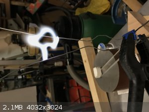
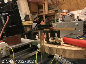
Hi All,
It's done! And it worked. An extrem fast and dirty assembly, but anyway I succeded in coupling an external HV ferrite transformer to my cheap chinese
welding inverter.
I run it for 20 min without problem (but not with max power).
I had no cooling in place and I dat a bad ventilation. But the inverter keeps completely cool. Only my transformer heated up a little bit.
I introduced an air gap of 0,3mm and I figured out a coupling capacity and that was the missing item. Because I had only 6 pcs. of 0,47uF caps on hand
it was not possilbe to draw the fullpower of the core, but it was enough to say it's a good prove of concept.
I made a small vid, but have first to find out how to load it up it's 53Mb...
[Edited on 1-5-2020 by FranzAnton]
[Edited on 1-5-2020 by FranzAnton]
Attachment: HV_test.mp4 (7MB)
This file has been downloaded 389 times
|
|
|
FranzAnton
Harmless
Posts: 45
Registered: 31-3-2020
Location: Austria
Member Is Offline
|
|
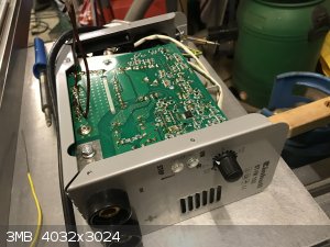
Hi again, today I did some testing to find the correct winding ratios and air gap and did some testing regarding the max. power which I can draw from
my external transformer and the inverter. First the bad news, but my cheap 100A welding inverter can deliver only 600 Watt continuously and that’s
for me too less... the good new is that my double fly back scrappy assembly keeps completely cool with that power. My load was a 2000Watt spot light.
Airgap approx 0,4mm and 7 turns primary windings. I measured 75V primary true rms.
So now I am at the point to think about a serious welding inverter or building up the whole IGBT driver from scratch (what I wanted to avoid) My cheap
Inverter is nice to play around and getting experience to dimension ferrite transformers
|
|
|
Twospoons
International Hazard
Posts: 1280
Registered: 26-7-2004
Location: Middle Earth
Member Is Offline
Mood: A trace of hope...
|
|
| Quote: Originally posted by FranzAnton |
I took a lot of information also from highvoltage forum and I saw a lot of real scrappy assemblies that worked fine so I think it's depending more on
the detailed experiance one will have. I was not registered as user there because it also costs a lot of time to give all the helpful people also the
feedbach which they deserve for their hints ..
|
Yet you are quite willing to ask for electronics help in a chemistry forum.
Seriously, go register there. Ask for assistance - people there are genuinely interested to see new projects. You wouldn't need to spend any more time
there than you are here - and you will have a larger base of experienced people to lean on.
As for your inverter, you might like to look at some of the high power induction heater drivers on Ebay - >2.5kW for 75USD. One of those should be
able to drive your transformer, with appropriate coupling. Again - ask on the high voltage forum as to which one would be best, so you dont waste
time and money on a dud.
[Edited on 2-5-2020 by Twospoons]
Helicopter: "helico" -> spiral, "pter" -> with wings
|
|
|
FranzAnton
Harmless
Posts: 45
Registered: 31-3-2020
Location: Austria
Member Is Offline
|
|
ok thank you for your hint. I will stop posting here. Pls. feel free to delete my posting(s) to keep the chemistry forum free of that stuff.
Kind regards
|
|
|
wg48temp9
National Hazard
Posts: 761
Registered: 30-12-2018
Location: not so United Kingdom
Member Is Offline
|
|
| Quote: Originally posted by FranzAnton | ok thank you for your hint. I will stop posting here. Pls. feel free to delete my posting(s) to keep the chemistry forum free of that stuff.
Kind regards |
Yes it is mostly a chemistry forum but its not exclusively chemistry, particularly as your goal is to make NO. I am interested in your experiments
and judging from the more than 200 view count so are others.
I hesitated to give you advice as its complicated and ideally you need a scope. You have done well to get as far as you have without destroying the
inverter, that is probably in part due to the robustness of the inverter design.
Usually flyback inverters have air gaps in there cores because the air gap can store more energy than the core material. A push pull inverter uses a
core in transformer mode without an air gap to reduce the required magnetisation current and reduce the number of turns for a given voltage.
Assuming your inverter is push pull and your added transformer is driven by a secondary winding of an other transformer you don't need an air gap in
your core or a capacitor. But you will need a sufficient number of primary turns to reduce the magnetisation current and hence the core flux below
saturation flux level for the core.
I suggest you put the two cores side by side as that will reduce the total number of secondary turns for a given output voltage. I am surprised you
got sufficient output voltage to start the arc on your ladder. Do you have a scope? Is the inverter push pull (at least two power devices not in
parallel) ?
[Edited on 5/3/2020 by wg48temp9]
I am wg48 but not on my usual pc hence the temp handle.
Thank goodness for Fleming and the fungi.
Old codger' lives matters, wear a mask and help save them.
Be aware of demagoguery, keep your frontal lobes fully engaged.
I don't know who invented mRNA vaccines but they should get a fancy medal and I hope they made a shed load of money from it.
|
|
|
Twospoons
International Hazard
Posts: 1280
Registered: 26-7-2004
Location: Middle Earth
Member Is Offline
Mood: A trace of hope...
|
|
| Quote: Originally posted by FranzAnton | ok thank you for your hint. I will stop posting here. Pls. feel free to delete my posting(s) to keep the chemistry forum free of that stuff.
Kind regards |
I wasn't suggesting you stop posting here - as has been said, your project is interesting us. I just couldn't understand why you would not want to ask
for help with the electronics in a power electronics forum. You will get better help with that side of the project that way.
Believe me people is both areas would like to see you succeed - I myself am an electronics engineer with a hobby interest in chemistry.
Helicopter: "helico" -> spiral, "pter" -> with wings
|
|
|
FranzAnton
Harmless
Posts: 45
Registered: 31-3-2020
Location: Austria
Member Is Offline
|
|
but I fully understand your kind remark. This is a chemistry forum and not electronics. Anyway thank you for your hints and ideas I got from You. I
will try to clean my threats as far this is possible (so otherwise be so kind and help me a last time in that cas) I will move on Monday to High
Voltage Forum where I am closer to the target group.
Pls. be so kind and remove my account too, because I am sure I will not use it in future
thanks a lot for the information I got from your forum during the years I wrote without registering!
|
|
|
WGTR
National Hazard
Posts: 971
Registered: 29-9-2013
Location: Online
Member Is Offline
Mood: Outline
|
|
I think this is a misunderstanding. We are more than happy to read about electronics here, especially when it comes to chemistry applications. The
two fields of study overlap in many areas. I design electronics to perform chemistry experiments, and I have never been a member of any other forums.
I think that some people noticed that while your research is very, very interesting (at least to me), that some of your electronics questions were not
getting very good answers from the members here. For this reason, suggestions were made to get extra help from the hv forum. The intention is not to
run you away from the forum at all, but to offer a helpful suggestion. We would definitely like to see your project succeed, and would like to see
you post it here.
This is a thread started by an administrator himself about a high voltage driver, and I posted there also:
http://www.sciencemadness.org/talk/viewthread.php?tid=31147
We certainly talk about electronics here, just not as often. You are not breaking any rules.
|
|
|
FranzAnton
Harmless
Posts: 45
Registered: 31-3-2020
Location: Austria
Member Is Offline
|
|
thank you WGTR for your kind words. Maybe misunderstanding -English is not my mother tonge as it easily can be seen-
I don't want to "stress" anybody with my posts and offtopic material in a chem board.
But if you and some other are interested I will tell you about my progress and also about things that did not work as I hoped. I think man can learn
also from failures (which were made by others as well)
I investigated a little bit in this induction heating 75$ hint, but found out that for my 2kW "project" it's not exactly what I need. Main problem is
that the e-bay boards are not running on mains power so a strong DC power supply is needed too.
I read a lot of killed Mosfets in the Mazzilli design and it's not easy to build effective snubber and other current limiting circuits around.
I also prefer a fixed switching frequency and a power control by PWM.
(so it's easier for me to desing my transformer)
So just a short summarize of transformer experiments:
Approx. 600 W with the weak inverter. Prim 7 Wgs. so I get out approx. 10 V/wdg. that's fine for my high voltage coil -need not so much windings and
can take care for good insulation.
To reach the 2kW a real serious inverter is needed and this will cost in the range of 400-600$. The cheaper ones will not be able to deliver 2kW
permanently.
So at this point I am really thinking about building an inverter by myself from scratch runnin directly on mains power 220V.
It sounds cheaper for me even if I burn several IGBT's and diodes on that way.
Advantage is that I can repair it by myself and I can design it exactly for my needs for the flat arc reactor.
I know this will be a long way, because I have not so much time to spend for my hobby, but I was on this topic for several years and was near to give
in...
There are not so many posts here about using a high voltage switching inverter running directly from mains, so I hope this is not too boring for you.
For me it's a big challenge because I am not so experianced with inverters but I am just reading an interesting web site http://www.lothar-miller.de/ to get me a little bit more inside that stuff.
If I find a fitting schematic I will share it here and you can watch me failing or not. If I have a reliable HV power source I start the arc chamber
project which I hope to increase my NO yields compared to run a jacobs ladder in a bulky glass vessel.
|
|
|
Sulaiman
International Hazard
Posts: 3555
Registered: 8-2-2015
Location: 3rd rock from the sun
Member Is Offline
|
|
designing and building a high voltage output switchmode converter of 2kW is not a simple matter.
Have you looked at microwave oven transformers for a simpler approach ?
(you can use a pair of similar models with outputs in series, or many units in parallel)
CAUTION : Hobby Chemist, not Professional or even Amateur
|
|
|
Twospoons
International Hazard
Posts: 1280
Registered: 26-7-2004
Location: Middle Earth
Member Is Offline
Mood: A trace of hope...
|
|
Designing and building any power supply of 2kW is not a simple matter.
Some of the solid state tesla coil driver designs should give you a good starting point - many of those are well over 2kW, and some run from 440V
3-phase.
Be aware that some sections of these high-power inverters can be unforgiving of sloppy construction - especially around the gate drive.
Also, and I trust you know this already, these things are lethal. Be careful with everything you do, assume everything is live.
- put bleed resistors on all your storage capacitors, they can hold charge a long time (I had a very nasty accident at work once because of that)
- put a polycarbonate blast shield over your inverter before you operate it, when things go bang you dont want to be hit by the shrapnel.
Also Simetrix is very useful for simulating the circuit before you build it. The free version lets you do quite a lot. There's also LTSpice, another simulator (which I dont like , but many people use.
Helicopter: "helico" -> spiral, "pter" -> with wings
|
|
|
WGTR
National Hazard
Posts: 971
Registered: 29-9-2013
Location: Online
Member Is Offline
Mood: Outline
|
|
| Quote: Originally posted by FranzAnton | thank you WGTR for your kind words. Maybe misunderstanding -English is not my mother tonge as it easily can be seen-
I don't want to "stress" anybody with my posts and offtopic material in a chem board.
But if you and some other are interested I will tell you about my progress and also about things that did not work as I hoped. I think man can learn
also from failures (which were made by others as well)
I investigated a little bit in this induction heating 75$ hint, but found out that for my 2kW "project" it's not exactly what I need. Main problem is
that the e-bay boards are not running on mains power so a strong DC power supply is needed too.
I read a lot of killed Mosfets in the Mazzilli design and it's not easy to build effective snubber and other current limiting circuits around.
I also prefer a fixed switching frequency and a power control by PWM.
(so it's easier for me to desing my transformer)
So just a short summarize of transformer experiments:
Approx. 600 W with the weak inverter. Prim 7 Wgs. so I get out approx. 10 V/wdg. that's fine for my high voltage coil -need not so much windings and
can take care for good insulation.
To reach the 2kW a real serious inverter is needed and this will cost in the range of 400-600$. The cheaper ones will not be able to deliver 2kW
permanently.
So at this point I am really thinking about building an inverter by myself from scratch runnin directly on mains power 220V.
It sounds cheaper for me even if I burn several IGBT's and diodes on that way.
Advantage is that I can repair it by myself and I can design it exactly for my needs for the flat arc reactor.
I know this will be a long way, because I have not so much time to spend for my hobby, but I was on this topic for several years and was near to give
in...
There are not so many posts here about using a high voltage switching inverter running directly from mains, so I hope this is not too boring for you.
For me it's a big challenge because I am not so experianced with inverters but I am just reading an interesting web site http://www.lothar-miller.de/ to get me a little bit more inside that stuff.
If I find a fitting schematic I will share it here and you can watch me failing or not. If I have a reliable HV power source I start the arc chamber
project which I hope to increase my NO yields compared to run a jacobs ladder in a bulky glass vessel. |
I agree with the safety cautions from Twospoons. This project must be made with care.
I have a #56-25 transformer that was given to me some years ago:
https://belfuse.com/resources/datasheets/signaltransformer/d...
This unit can deliver 56V RMS at 25A and 50-60Hz from a 115V service. That's 1.4kW. It is easy to add a rectifier, choke, and filter capacitors, to
make an isolated linear power supply. Brand new this transformer is about $300, but other types or used models can be much less expensive or maybe
free.
The point is that the isolated high power DC supply is not difficult to achieve. Even batteries or solar panels could be used. The difficult part is
converting to the high voltage/high frequency AC.
I do not like the Mazilli driver design. I also agree that it is too easy to damage the power MOSFETs. I think the biggest problem with the design
is that the MOSFET gates are always biased to be "ON" regardless of whether the circuit is oscillating or not. A big improvement would be to allow
the oscillations to generate the necessary bias for the MOSFET gates instead. If the oscillations stop then the MOSFET gate bias drifts to zero and
the drains turn off. This would make the design much more stable. To initially start the oscillations in the circuit some sort of temporary
injection of gate bias would be needed.
I still prefer my other idea of using a 70-150V DC power supply to deliver amperage to the spark gap, while using a high voltage flyback converter to
periodically ionize the spark gap. This allows one to increase the average power simply by increasing the frequency of the flyback gate trigger. I
think this design is much safer overall.
|
|
|
FranzAnton
Harmless
Posts: 45
Registered: 31-3-2020
Location: Austria
Member Is Offline
|
|
Dear All,
thank you again for your ideas!
I experimented in the past also with MOT's and found out that one can take only 400-500Watts continous with good cooling.
Also the "tesla" style with spark gaps is not so sexy for me. It's a quite robust design, but the power losses are significant.
So finally I will stick to a primary switched inverter design which is running on mains 220V. If I can get this running, it will be able to stand a
100% duration time (cause I will let it run for several days).
If I focus on the core unit and skip the PFC part I can take out some complexity. (I know this is not really allowed, but I keep the grid distortions
low by using a filter directly on the mains side)
A switch on delay for loading my filter caps and then I will use as driver and controller for the IGBT the old style IR2153 for my core circuit.
IGBT's for 600V and 40A are in the range of 10$. So I am nearly done with the rough circuit design and will post it this week then we have something
to discuss.
What is still missing is an overcurrent protection and some overvoltage protection in idel mode. So idle mode is something critical.
Overcurrent can be done with some easy chocke on the high frequency side.
Even it's a self done SMPS an efficiency of 80% + should be possible.
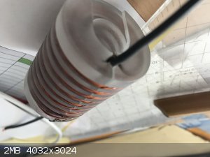
I attached a pic of one of my HV coils I killed on weekend because I did some testsing without soaking it in epoxy. (I hoped for the chamber design)
but the killer was the idle mode. You I can do not only "dirty" designs 
|
|
|
Twospoons
International Hazard
Posts: 1280
Registered: 26-7-2004
Location: Middle Earth
Member Is Offline
Mood: A trace of hope...
|
|
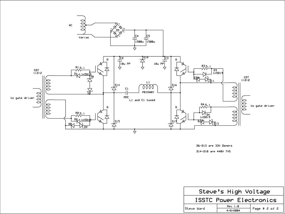
Not spark gap - Solid state.
Like this
Helicopter: "helico" -> spiral, "pter" -> with wings
|
|
|
FranzAnton
Harmless
Posts: 45
Registered: 31-3-2020
Location: Austria
Member Is Offline
|
|
Wow! Thank you, Steves HV page was not in my search until now. This is very helpful for designing my inverter.
A lot of protection stuff too and how to calculate the right values.
--> I will walk through that stuff and try to adapt the useful parts for my design.
I also found a PFC for his 8kVA low voltage swithing inverter and I will try to understand an so maybe also bring a PFC (which I initially wanted to
skip) in my circuit.
|
|
|
WGTR
National Hazard
Posts: 971
Registered: 29-9-2013
Location: Online
Member Is Offline
Mood: Outline
|
|
I also looked through Steve’s website. Very interesting. Thanks for the link Twospoons.
I have designed drivers similar to this before, but with a half-wave design. Here is a schematic of one that I built.
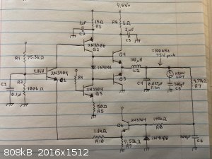
This particular circuit converts about 10V to a higher voltage (75V), enough voltage to drive a small neon gas discharge bulb. Feedback is provided
back to the input to cause this circuit to oscillate at about 100kHz. This circuit was just a design exercise and a curiosity. I don’t suggest
that this circuit is exactly what you need, but some design elements may provide useful ideas to you.
Q2, Q3, Q4, and Q5 form the half-wave driver stage. Q1 sets the bias for the push-pull driver and level-shifts the feedback voltage. L1 and C4 form
a series resonant circuit. Since inductive reactance is a +j term, and capacitive reactance is a -j term, the two values cancel out at resonance,
allowing very large currents to flow through this resonant circuit if the tuned circuit is unloaded. These large currents can produce large voltages
across each series resonant element, since voltage equals I*Z, Z being the complex impedance of the inductor or capacitor.
Since L1 and C4 add to produce essentially zero impedance at resonance, it looks like a short circuit exists at resonance at the output of the Q4/Q5
driver when there is no load on the tuned circuit. As the circuit is loaded, this load is reflected back to the output of the driver. Not only is
power transferred to the load, but this loading prevents Q4/Q5 from being over-worked. You cannot run this circuit unloaded at the center resonance
of L1 and C4, since this will cause the driver transistors to fail.
The way this problem is fixed is by adding the R7 and C6 phase shift network. At the resonant frequency of L1 and C4 (about 100kHz), an extra -45
degree phase shift is added to the feedback loop. This pushes the oscillation of the circuit slightly off center resonance, and prevents the L1 and
C4 reactances from canceling completely. This provides a minimum load to the output of the driver of some complex impedance. As the oscillation
frequency changes with loading, the phase shift of R7 and C6 changes also. If the frequency drops too far for some reason, it can move too close to
the L1 and C4 center resonance and blow up Q4 and Q5. If loaded down too much, the frequency can rise, causing additional phase shift and pulling the
oscillation frequency too far off resonance, limiting output power. One way I have addressed these issues is by designing an RC phase shift network
that provides a constant phase shift over a 2:1 frequency range, while also providing a relatively constant amplitude response. The design of this
was not trivial. I haven’t posted it here, but could if needed.
Q6 is a unity-gain buffer. R10 provides a gain-adjusted feedback to the emitter of Q1.
To create higher voltages using a circuit like this, it is possible to wind a larger secondary over L1 or use higher supply voltages.
For better efficiency, it is possible to add an additional circuit in the feedback loop that converts the sine wave to a series of PWM pulses, similar
to how a pure sine wave power inverter works.
[Edited on 20-05-07 by WGTR]
|
|
|
Twospoons
International Hazard
Posts: 1280
Registered: 26-7-2004
Location: Middle Earth
Member Is Offline
Mood: A trace of hope...
|
|
I love seeing ppl do discrete designs like that - its becoming something of a lost art these days. I'd use a few BJTs over an op-amp any time I can. I
personally think some of my best work has been my discrete designs - the puzzled look on a colleagues face is priceless.
Back on topic - many of the big chip vendors (TI, NXP, ST, IR etc) have LLC controllers that would be ideal for this project, given the desired power
levels.
Another suggestion is to use a Cockroft-Walton multiplier on the output to achieve arc ignition - once the arc is struck the multiplier ceases to
operate and the current just flows through the diode string. This would allow better optimisation of the transformer for driving the arc, which will
be at a lower voltage and higher current than required for ignition.
Helicopter: "helico" -> spiral, "pter" -> with wings
|
|
|
FranzAnton
Harmless
Posts: 45
Registered: 31-3-2020
Location: Austria
Member Is Offline
|
|
Here comes my design mixed from differnet sourves in the web. It is powerd from mains, and it's basically the rough version without any protection
circuit, which I will add later. At least a switch on delay for loading my big caps on mains for the 310V DC. The 2153 is a general purpose PWN
switching controller which should be able to drive the IGBT's directly. If not I will add some extra drivers. IGBT were 600V an 40A types. The extra
power supply for the 2153 I did not draw, but will use an old wall adapter for my old wlan supply.
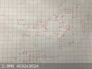
Should finally be capable for 1.5-2 kW
[Edited on 8-5-2020 by FranzAnton]
|
|
|
WGTR
National Hazard
Posts: 971
Registered: 29-9-2013
Location: Online
Member Is Offline
Mood: Outline
|
|
| Quote: Originally posted by Twospoons | | I love seeing ppl do discrete designs like that - its becoming something of a lost art these days. I'd use a few BJTs over an op-amp any time I can. I
personally think some of my best work has been my discrete designs - the puzzled look on a colleagues face is priceless. |
I know exactly what you mean. I've seen these puzzled expressions many times in my career, and usually from senior level engineers! I was hired by
an analog guy (who was like a grandfather to me) when I was a 17 years younger version of myself. He taught me analog; I taught him digital. We both
learned a lot from each other. There are still some things that are simply more difficult/expensive to do digitally, but can be designed in analog if
you understand how to convert problems (and the electrical components) into the "math domain" and play with the math.
| Quote: Originally posted by Twospoons | Back on topic - many of the big chip vendors (TI, NXP, ST, IR etc) have LLC controllers that would be ideal for this project, given the desired power
levels.
Another suggestion is to use a Cockroft-Walton multiplier on the output to achieve arc ignition - once the arc is struck the multiplier ceases to
operate and the current just flows through the diode string. This would allow better optimisation of the transformer for driving the arc, which will
be at a lower voltage and higher current than required for ignition. |
Are you thinking of something like this?
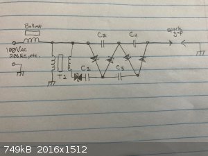
I haven't thought this one through all the way, but the idea is that the multiplier would be driven by a high frequency, high enough that the arc
cannot naturally extinguish between cycles (1kHz may be high enough, but higher is better). The avalanche diode would be selected such that after the
arc is initiated, the voltage drop across the ballast would prevent the multiplier stages from drawing power. If DC voltage was being supplied from
the main supply then it could certainly pass through the diodes once the arc initiates. However, with AC voltage the energy could simply pass through
C2 and C4 on its way to the spark gap.
That's an interesting circuit FranzAnton. I am interested to see how it works when you finish building it. I wonder if the 2153 will provide enough
drive to the IGBTs for high speed switching. I personally like to use SiC MOSFETs (like these: C3M0120090D). They are fairly cheap, work at high voltages, are easy to drive, and are very fast.
I am also interested in your idea for getting >10% NO concentration from the reactor, This is the most interesting part of the project, in my
opinion. As you know, rapid cooling of the hot gasses is important. Are you thinking to rely on the rapid cooling of air by expansion through a
venturi nozzle? I am not certain if I understand one of your earlier posts about this.
I could probably get high concentration of NO with my previous reactor design by running the same gas through multiple arc reactors. This is because
the arc is only active for a very, very, short period of time before the magnet blows it out each time. The duty cycle of the reactor is very low.
This allows the cooler air around the hot gasses to cool the reaction zone very rapidly. The reactor itself was very cool to the touch. Even the
electrodes were only slightly warm.
If the hot gasses were given time to mix with the cooler air, then this will give time to obtain a homogeneously low concentration of NO before the
gasses were again run through the next arc reactor. This would prevent most of the NO from being decomposed by the following reactor(s) hopefully,
since only a small part of the bulk gasses are in the reactor hot zone. At some concentration of NO efficiency would likely drop, since just as much
NO is being decomposed as was produced by the following reactor.
|
|
|
| Pages:
1
2 |


