zinc finger
Harmless

Posts: 25
Registered: 30-7-2019
Location: Germany
Member Is Offline
|
|
Help with photomultiplier tube
Hi there,
first off, I must say: my electronics skills are quite limited and mostly based on experiences of opening electr(on)ical devices as a child.
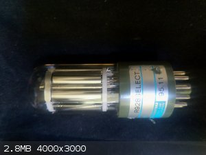
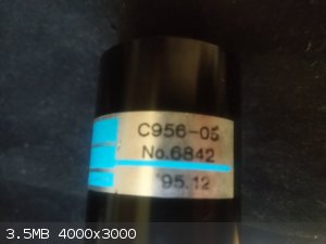
Recently I cheaply sourced a beautiful photomultiplier tube R928 SELCET (https://www.hamamatsu.com/resources/pdf/etd/R928_R928P_R955_R955P_TPMS1091E.pdf) with a C956-05 socket (maybe DP-Type?) and some nameless control
unit.
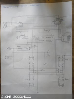
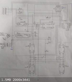
The first thing I did was to reconstruct the circuit in EAGLE. And I figured out that it should do the following:
I could not identify anything that can provide the high voltage inside the unit so it probably is mad in the socket
All the ICs and Relays need about 5V and this should be the overall voltage supply.
The two coupled OpAmps (AD549JHZ and LT1013CN8) connected to the HV-Connector have their output at PIN 1 of the DB-15 connector. I belief this is the output.
The TTL IC (SN74156N) controls 4 celduc relays (D31A3110). They switch different resistors between the anode and ground for some gain adjustment?
There is a fifth relay (PRMA1C05B) switched by an NPN-transistor with its base at PIN 15 of the DB-15 connector. This might provide some additional gain adjustment.
I then hooked up my oscilloscope to PIN 1 and Powered the PINs 3 and 8 at the DB-15 connector with +5V and the PINs 6 and 10 to ground. When powering
PIN 15 with +5V I can hear the relay click. Unfortunately my Oscilloscope shows no reaction at PIN 1 (or any of the other PINs) when I change the
Illumination of the tube. I normally have the tube covered with four layers of molleton to not overwhelm it.
Any idea why I can not measure any response? Is someone maybe familiar with the standard configuration of such control circuits?
I greatly appreciate any help! 
Pictures will follow...
[Edited on 19-5-2021 by zinc finger]
[Edited on 19-5-2021 by zinc finger]
[Edited on 19-5-2021 by zinc finger]
|
|
|
Sulaiman
International Hazard
Posts: 3558
Registered: 8-2-2015
Location: 3rd rock from the sun
Member Is Offline
|
|
I have a Hamamatsu pmt,
Look in the datasheet that you linked to,
notice the external resistor chain supplying the dynodes.
You need either a high voltage negative supply and a resistor chain
or a Greinacher (Cockroft-Walton) multiplier with one stage per dynode.
You could also buy a commercial pmt psu.
There are (or used to be?) lots of application notes on the Hamamatsu website.
CAUTION : Hobby Chemist, not Professional or even Amateur
|
|
|
zinc finger
Harmless
Posts: 25
Registered: 30-7-2019
Location: Germany
Member Is Offline
|
|
Good news
Thanks for the tip with the Hamatsu website, that really helped a lot.
What does PSU stand for? 
I want to clarify: I have got The tube, the socket and the control unit as one bundle. The previous owner told me, I would not need anything else to
generate the high voltage.
What would have helped a lot is some more information about the socket. Unfortunately I could not find anything about that particular model online.
However thanks to some more reverse engineering I found out, that it is indeed a PG-type socket. Meaning (as I already suspected) it contains the
HV-generator as well as the resistor chain for the dynodes.
More things I found out about the socket:
The supply voltage for the control unit and the socket is 5 V
The supply +5V are to be attached to a red wire
While the supply voltage is in this low range, the output from the tube is directly coming from the HV-anode
GND is generally applied to the black wire
In my setup the blue wire is also on GND (this for reference voltage)
The white wire controls the high voltage output of the socket. It must be adjusted between 0 V and 5V.
The last point is the reason, why I did not get a signal out of the circuit so far. I had the white wire on GND which corresponds to 0V at the HV
output.
Now the good news:
After I corrected this error I got a PWM-signal at PIN1 whit an amplitude of 0.5 V, 3.8 V above GND with a frequency of 5.3 Hz. This was achieved with
the following settings to my control circuits DB-15 connector:
Oscilloscope @ PIN1
+5 V via lab power supply @ PIN3, PIN7, PIN8, PIN14, PIN15
GND @ PIN6, PIN10
PIN11 corresponds to the HV control from the socket and was set to ~ 3 V using a simple voltage divider
So far, I don't quite understand how the anode signal is converted into the PWM-signal. Also the signal is pretty noisy and the sensitivity is not
high enough for my purposes jet. Luckily there are a few things which can be adjusted:
The HV control voltage @ PIN11
The potentiometer R10 inside the control unit (adjusts the first OpAmp)
PIN15 [binary, 0, 5 V]
PIN14 [binary, 0, 5 V]
PIN7 [binary, 0, 5 V]
The last three stated PINs control the relays which switch resistors between the anode output and GND.
I am so glad that it finally works and can't wait to figure out the optimal settings and putting it into my spectrometer.
If anyone needs more information about this model of socket or the control unit - I will happily share everything I found out with you
|
|
|
Hoffit
Harmless
Posts: 21
Registered: 12-8-2019
Member Is Offline
Mood: Excited
|
|
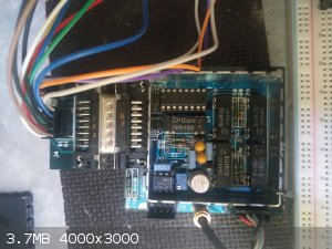
I fail to find any high voltage supply from your photos. Datasheet spec is 1250V and usually you need at least a resistor divider for the dynodes. I
would expect the control board to have some transformer/inductor for voltage step up (seems throughhole, I assume no smd inductors or such on the
other side of the board). Unless you have a socket that has integrated high voltage supply, you seem to be missing pieces.
I'd first make sure there is voltage between anode and cathode (pins 10 and 11 based on liked datasheet). However, that can be 1250V or so (not for
the scope or most multimeters). Usually the dynode voltage chain is made with resistor dividers that is pretty high (like 100Mohm from end to end), so
usual DMM 10meg impedance will load it way down.
You need probably some reverse engineering. Wikipedia has good page about photomultipliers.
I once made a circuit for radiation detector but it is based on pulses that may or may not be your use case. I never checked how static light
detection is implemented but pulse light is usually picked up from the load resistor through a capasitor.
You are lucky to have a socket. I used a very old russian tube that no socket could be found. Making a socket myself was an ..ummm.. experience
|
|
|
zinc finger
Harmless
Posts: 25
Registered: 30-7-2019
Location: Germany
Member Is Offline
|
|
I am especially lucky about the socket because the high voltage power supply really is integrated in the socket. I am quite certain that this is the
case because I get a illumination dependent signal from the tube now. The resistor divider is in the socket too and I measured about 316 kOhm for each
individual resistor. I also added some labelling to the circuit diagram from what I found out so far.
As I do not have high voltage measuring equipment on hand I prefer to avoid testing the anode-cathode voltage
Did you use scintillators for the radiation detection or was it still in the spectral range of your tube? I plan to use the tube in an (until now)
normal spectrophotometer to measure fluorescence.
Uh what happened? I hope the tube and involved personnel survived 
As I mentioned I do actually get some response from the device now. It is not nearly as sensitive as I hoped though. Only if I move a typical LED very
close (~5 cm) directly in front of the optical window, I get some response. But it is only a maximum of about 300 mV for the LED even closer. I hope I
did not destroy it yet.  But I could not find out if they take damage from too
much light.(?) Of course there are multiple possible reasons: just the wrong control circuit (maybe it was made for a whole other purpose), faulty
tube, faulty socket, faulty opamps in the circuit etc. But I could not find out if they take damage from too
much light.(?) Of course there are multiple possible reasons: just the wrong control circuit (maybe it was made for a whole other purpose), faulty
tube, faulty socket, faulty opamps in the circuit etc.
So far it worked best when I set PIN15 high and removed the power from the TTL by setting PIN8 to GND. Also the signal got a lot better when I
grounded the control unit better. The last signal I measured was definitely the expected analogue signal but I measured something very PWM-like which
I can not explain.
|
|
|
Texium
|
Thread Moved
29-11-2023 at 20:54 |


