| Pages:
1
2 |
Rainwater
National Hazard

Posts: 799
Registered: 22-12-2021
Member Is Offline
Mood: indisposition to activity
|
|
Extending the upper voltage the adc can read can be done with a simple resistive divider at the cost of full-scale resolution.
Depending on which mcu, you likely have a 8bit to 12bit adc.
Full scale resolution = max voltage ÷ 2bits
5v ÷ 28 = 0.01953125 volts LSB
30v ÷ 28 = 0.1171875 volts LSB
So it really depends on how accurate you want it. Andrea Spiees on youtube is who to watch.
https://www.youtube.com/channel/UCu7_D0o48KbfhpEohoP7YSQ
Charging to a higher voltage can be accomplished by using the arduino as a buck and boost dc converter controller, requires a output buffer(opamp
capable of 150mA output), mofset, inductor and diodes. Its not a great way to do it, but saves you the trouble of buying more stuff and gives you
complete digital control.
[Edited on 17-4-2023 by Rainwater]
"You can't do that" - challenge accepted
|
|
|
zimirken
Harmless
Posts: 17
Registered: 15-3-2018
Member Is Offline
Mood: No Mood
|
|
I think I've finally landed on a pump that actually works. The two pumps I was previously using couldn't be pulsed longer than about 150ms at a time
or else the cell would pressurize and leak. Then one of the motors got some corrosion in it. However, the actual pump part which is abs and silicone
AFAIK was in perfect condition.
So I took the pump parts off the motors and attached them to one of those little yellow gear motors. The pumps have three chambers and the motor
rotates the diaphragm to alternately pump each chamber. However now I just have a piston that pumps all three chambers together. This also adds more
plastic and brings metal parts even further from the electrolyte. This new pump has been working perfectly with zero issues for quite a few days. It
provides a steady flow, and draws about 0.1 amps at full flow. It also responds well to pwm speed reduction.
I also made a couple small modifications to my control board. I installed a super capacitor pack I found in my box. This provides enough energy
storage to power the motor through battery voltage sags, without significantly affecting my charge/discharge data. The super capacitor is charged from
the battery, and powers the arduino and pump. I'm also getting to a good point on the programming of the control board as well. The pump pwm is
adjusted based on the charging/discharging current. Below 100mA, it's in idle mode, where it only runs the pump if the voltage sags. It cuts out if
the voltage sags below a certain voltage during idle as well, like when the battery is dead.
I haven't had a lot of time to work on it besides getting the pump and controller working well. I am building yet another cell stack though.
I read some papers/patents on trying a single flow battery. One tank is circulated with no seperator, and the plating action is what separates things.
However this only seems to work well with zinc bromine, as I whipped up a quick cell and couldn't get it to work well at all.
I just ordered some glutamic acid HCl, that I'm going to use to make ion exchange membranes with based on the directions from someone on the
explosions and fire discord. This will be the new separator for my new cell stack.
I'm also lightly considering sulfate instead of chloride. I can buy big bags of iron sulfate and ammonium sulfate from the local hardware store.
However one paper showed that sulfate only had around 25% of the current performance of chloride.
Here is the pump. This is the minimum speed.
short clip
|
|
|
Rainwater
National Hazard
Posts: 799
Registered: 22-12-2021
Member Is Offline
Mood: indisposition to activity
|
|
| Quote: | | I'm going to have to rebuild it so I can charge from higher source voltages. Also, I have come up with a few different ways to elevate the negative
battery voltage sensing, so I don't have to guess during discharge. |
To read negitave voltages with an arduino you need a voltage divider.
The op amp acts as a sinking 5V voltage source.
Needs to be rail to rail or powered from higher voltage for best dynamic range
R1 and R2 is a voltage divider that takes a -15V signal to about 0V
R2 and R3 is a voltage divider that takes a +20V signal to 5.0V.
D1 and D2 are protection diodes for overvoltage conditions
Input Range -15V to +20V.
Input impedance 1M ohm
Output Range 0 to +5V.
1V change in the input results in 0.143V change in output
8 bit ADC resolutions will be 0.13671875V LSB
Calibration in software can be done to correct for any tolerance errors of resistors you have. All errors will be linear.
This configuration does not require a dual rail setup.
If you had a dual rail setup, it would be much easier.
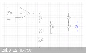
https://everycircuit.com/circuit/6521735993884672
[Edited on 7-5-2023 by Rainwater]
"You can't do that" - challenge accepted
|
|
|
NickBlackDIN
Harmless
Posts: 10
Registered: 10-5-2023
Member Is Offline
|
|
This is a fascinating read, and creepily close to myself, similar budget, similar headaches, similar strength/weaknesses, we both even come from the
automation industry lmao. (Though I work as an elevator technician now, better pay) biggest difference is I'm going the solid state route rather than
flow battery (and using Na chemistry rather than zinc/iron)
Just a few things I was thinking of while reading your log. I know you're already making some ion exchange membranes, but a cheap option that'll be
better than cardboard is fired clay, (learned this from scrap science: https://youtu.be/6BThiJpbBJQ)
Also, what I would personally try is to first crystalize out your chemistry (sounds like ZnCl2 & FeCl3?) Then redissolve so you know your
chemistry is balanced, then use a different acid like acetic acid (vinegar) to adjust the ph, the acetate should be less desirable then the cl, and
therefore (hopefully) cause less interference. But that is just a wild guess of something I would try if I was in your shoes. (I'm no chemist though,
so take my musings with a grain of salt)
Regardless, two thumbs way up, I'm really enjoying following your updates!
|
|
|
Sulaiman
International Hazard
Posts: 3558
Registered: 8-2-2015
Location: 3rd rock from the sun
Member Is Offline
|
|
Some thoughts
For proof of concept experimenting you only need a single cell.
Multiple series cells would only be required if you need a practical working battery.
Although chemistry is a very important part of battery manufacture,
Reliability is probably more important,
and that requires A LOT of time consuming and quite extensive research.
Maybe a single cell design
(possibly with a boost converter such as a 'joule thief) is more practical for experimentation?
CAUTION : Hobby Chemist, not Professional or even Amateur
|
|
|
zimirken
Harmless
Posts: 17
Registered: 15-3-2018
Member Is Offline
Mood: No Mood
|
|
Honestly, my physical construction is at the point where my only issue is leakage, and that's caught by a tray underneath the cell stack. The cell
stack and pumps and whatnot seem to be finally working well. I have a needle valve on the exit of each half cell for making sure the flow is even.
During charging, the voltage across each cell is pretty even as well.
So I got a big bag of iron sulfate from the hardware store for cheap to try, as I'm tired of everything rusting within a 10 mile radius. I made a
standard electrolyte solution (1-1.5M FeSO4, 2M NaCl, 0.3M ascorbic acid) I tried putting a few amp hours into it, and when I went to discharge it, a
bunch of black hydroxide came out. The negative tank ph had risen too high from hydrogen generation. However the cell stack without any circulation
managed to light a breadboard full of LEDs all day long.
I'm taking a step back to re-evaluate things. I'm almost out of interest, but I have one more thing I want to try that may help some of the issues.
I'm going to try to rebuild the battery into a primary battery. I'm going to use sheet steel anodes that will be consumed. I'll have a single tank
setup, and redesign the cell stack into individual cells that can be easily disassembled. The single electrolyte will be either Iron 3 chloride or
iron 3 sulfate, with NaCl supporting electrolyte. Physically I want to mount each cell above a little catch trough which will make any leaks
irrelevant. I'll also probably scale back to 2 cells to start. I've got a good boost converter that works down to 0.6 volts or so.
Each square centimeter of steel has the potential to give about 0.75Ah per millimeter of thickness. For $6 I can buy about 500 watt hours of sheet
metal. Or I can try to design the cell to squeeze (free) steel chips together.
Since I'll be using sacrificial iron anodes, I am now free to recharge the electrolyte outside the cell in a separate apparatus. If I use chloride, I
should be able to regenerate the ferrous chloride back into ferric chloride with a bubbler or drip table or something similar. Otherwise it should be
pretty easy to set up a separate electrolysis setup to pull the extra iron back out.
This will separate the charging and discharging processes, and will allow me to break things down into two more manageable sections. I think one of
the issues I'm running into is uneven charging. Some areas of the cell aren't getting good electrolyte flow, and then start making hydrogen instead of
plating iron or whatever. I measured my pump and each pump half is about 120mL/min, so I know I've got good flow.
My main question is thus: is there an easy way to check my electrolyte to find the ratio of iron 2 to iron 3? I need some way of figuring out if the
electrolyte is fully recharged. In theory, during electrical recharging, the positive electrode shouldn't make many bubbles if any until it runs out
of iron 2 to convert to iron 3, right? So If the positive is bubbling I know I'm done?
|
|
|
NickBlackDIN
Harmless
Posts: 10
Registered: 10-5-2023
Member Is Offline
|
|
I would Hazzard a guess you can keep track of the oxidation state with a white LED and some kind of optical sensor + Arduino to detect colour values,
2+ and 3+ should have different light absorption patterns.
Also if you do end up abandoning this project, let me know, I'll gladly pick up the torch.
[Edited on 15-5-2023 by NickBlackDIN]
|
|
|
| Pages:
1
2 |


