chemoleo
Biochemicus Energeticus

Posts: 3005
Registered: 23-7-2003
Location: England Germany
Member Is Offline
Mood: crystalline
|
|
Laser Scale - Homemade
BlindAngel asked me to post this - as he seems to have trouble to log on, with the password issue we had going on here of late....
Here's my idea:

1 is where you place the weight
2 is the counterbalance to make the balance arrive to 0 - obviously the heavier the two weights on either side of the scale, the less an effect a
small weight addition to the right side will have...
3 is a laser (a cheap pocket one, which you get as gifts etc)
4 is a semi-circular (or even flat) graduated piece of plastic, wood etc, which is fixed in relation to the rest of the apparatus
5 is a rotating miror that rotates around the big spot (it is attached to the blue string)
6 is a mirror at 45°
Red = Laser
Blue = a piece of string
You need to create a balance that is balanced on the triangular part (like most scale), where the counterweight/balance on the left side is attached
to a pulley system to the top of the rotatable mirror (Btw, at the 0 position the rotatable mirror should make the laser go down, at the end of the
graduated semi-circle). Once the system is balanced (with no weight on it) you mark it on the graduated piece 4, with a big 0 (zero weight). Then
place a gram weight, which is supposed to be accurate, onto the right side of the balance (as if you would weigh something); once the scale is stable
you mark where the laser intercepts, and this will be 1 gram. Then you do the same with 2 grams, then 3...etc..etc.. until you have no more space on
4. What comes now has to be verified, but if the distance between each gram marks are equal you can simply separate them in 10 to have 0.1g then if
you can, reseparate to have 0.01g... I suspect that because we use semi-circle the distance would be the same, but if it is not the case, use a good
old TI-8x calculator or something that draw plots and find the relation between each mark, by doing this you should be able to determine other points.
I think that this idea is viable if it's well done and well calibrated, i would like to have feed-back (and if someone want to give it a try
it'll be nice)
[Edited on 11-4-2004 by chemoleo]
Never Stop to Begin, and Never Begin to Stop...
Tolerance is good. But not with the intolerant! (Wilhelm Busch)
|
|
|
chemoleo
Biochemicus Energeticus
Posts: 3005
Registered: 23-7-2003
Location: England Germany
Member Is Offline
Mood: crystalline
|
|
My own thoughts
I do think this idea merits attention, if setting up the whole thing is done properly.
In principle, the laser is not needed, because, a pen could be attached to 5, and produce the same effect.
However! - a pen, and the extension to it, has a MASS, and therefore changes the balance by pulling it down (whose effect on the string increases as
the mirror lowers).
While a laser can produce accurate measuring over larger distances to 4 (the graduated board), because it is a parallel beam that doesnt defocus.
This means, a great accuracy can be achieved potentially, providing the gram weights are accurate themselves, providing that the string
doesnt stretch/expand under increasing weight (which I don't think is a problem at gram amounts), and providing none of the parts that hold the
string move even a fraction of a millimeter.
Then - of course it's not necessary to use a circular version of 4, a flat one is preferable, probably. Why? Because, if you wnat to achieve high
accuracies, one has to get a perfectly made semicircle, that is exactly in the correct position so that the circular
rotation of the laser contacts it. Otherwise, one gets angular effects, which will less the accuracy.
So... a flat pane would be ok. It is easy to calculate the separation marks on the graduated board - remember the law relating to the angle (of the
laser) alpha in a triangle, which contains a 90 deg angle, too?
Never Stop to Begin, and Never Begin to Stop...
Tolerance is good. But not with the intolerant! (Wilhelm Busch)
|
|
|
Tacho
National Hazard
Posts: 582
Registered: 5-12-2003
Member Is Offline
Mood: No Mood
|
|
My electronic scale (the cheap one you find at e-bay, price equivalent to 25 euros) weights up to 200 g with a precision of 0,1g.
That’s 1 part in 2000.
If the projection screen for the laser was 2 meters long, the laser spot would have to be significantly smaller than 1 mm to match the precision of
those cheap scales. Cheap lasers don’t make such small spots at a distance that would allow a 2m screen.
The mechanical part has to mach such precision. For your design you would need at least two bearings. Requires a lot of time to do them properly and
mount in a sturdy setup.
I have made four attempts to built a precision scale:
#1 - Incidentally, it was about the same Idea you had! The laser thing. It was a huge failure, but I learnt a lot about scales.
#2 – My favorite. Was a double bean scale. I was very lucky. It worked nicely, could weigh up to 100g with a precision of 0,1g.
#3 - A precision single bean: 10g, +- 0,05g. No good. To difficult to work with. The breath would unbalance it.
#4 - My masterpiece. Was this incredibly complicated electronic scale. Delicate bearings, magnets, coils, optical sensors. You would measure a current
in a digital amperimeter and convert it to weight. Not very practical.
If you are going to built a scale just for fun, I suggest you start with a double bean. Do simple prototypes first.
And use magnetic dampening. It helps.
|
|
|
Tacho
National Hazard
Posts: 582
Registered: 5-12-2003
Member Is Offline
Mood: No Mood
|
|
Two of my precious scales.

On the first picture, the aluminium structure on top is what is left of my laser scale. It used couple of strong magnets repelling each other as a
logarithmic elastic "coil".
The complicated stuff below, shown in some detail in the lower picture is what you get when you decide that "you really can do it!"
Had more frustation than fun building them, but they taught me to respect and admire every precision scale.
|
|
|
Marvin
National Hazard
Posts: 995
Registered: 13-10-2002
Member Is Offline
Mood: No Mood
|
|
I think the most important thing for a lab scale is that it is reliable, and this is the hardest thing to achieve at home.
An idea I had some time ago was to do away with finely machined parts, bearings, unreliable springs entirly by designing a levitating electrobalence.
Levitating small magnets, or bits of iron is quite a common trick even without superconductors. An electromagnet driver is supplied with negative
feedback to keep the iron in space. Either a change in inductance of the coil itself, or an optical sensor provides the correction. Its used a lot
in shop window displays. Since the current in the coil depends very accuratly on the weight of the iron being levitated, it should work very well as
a weight sensor. Essentially, no moving parts, no friction.
Unfortunatly I found out later the idea was too similar to existing methods and wouldnt have been patentable so I stopped thinking along those lines.
I do think it has the potential to be a very sensitive balence for home building if someone is good at electronics. Accuratly determining the current
is probably the hardest part. Feeding those results into a computer to remove non linear effects would probably be needed, and that means quite a lot
of calibration.
Making a unit that would hold more than 100g or so might require a very large electromagnet with a hefty driver.
|
|
|
Tacho
National Hazard
Posts: 582
Registered: 5-12-2003
Member Is Offline
Mood: No Mood
|
|
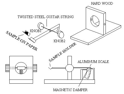
This is an idea I NEVER TRIED, not even a simple test, but has many interesting features:
It is very easy to build without sophisticated tools and can easily be adapted to the laser or light beam idea.
It uses a twisted steel guitar string not only as the elastic “coil” but also as one of the bearings. In fact, in this less precise
version, the only bearing, because the sample goes on on a piece of paper in a V shaped support. If you are careful to do a good distribution of the
sample you get a more precise reading. Obviously this version holds only small samples.
The knobs have to be adjusted and then fixed, with a screw for example.
|
|
|
Geomancer
Hazard to Others
Posts: 228
Registered: 21-12-2003
Member Is Offline
Mood: No Mood
|
|
I don't know what type of precision we're looking at here. It may be important to look at thermal effects. Notably, neither the Tacho nor
the Marvin balance is compensated for this. If I was to go out and build a balance right now, other than a simple single beam, I'd go with a
Marvin type design, using two coils instead of a permanent magnet or hunk of iron, with circuitry scavanged from commercial levitation products, if
adaptable (depends on how they sense stuff. Having two loops might confuse inductive sensors.). Output would be read with a multimeter.
IIRC, one of the more recent Amatuer Scientist columns had a gizmo that involved nulling magnetic force, with optical sensing. Anyone know the
details?
|
|
|
Tacho
National Hazard
Posts: 582
Registered: 5-12-2003
Member Is Offline
Mood: No Mood
|
|
Oh, Geomancer, I'm not saying this is a better design. Not even a good design! It's in fact very limited, umprecise and poor. I just wanted
to present the idea due to it's sheer simplicity and unusual construction, as inspiration.
This is not a competition between me and my good friend Marvin.
Marvin's idea is very good and, in fact, the complicated scale pictured in my previous post uses a similar principle: The coil pulls the lever to
given position, an optical feedback sistem holds it there and a multimeter reads the current (kept constant by the circuit - edit: to a given weight,
of course).
Of course, the bearings are not magnetic, unfortunatelly.
[Edited on 14-4-2004 by Tacho]
[Edited on 15-4-2004 by Tacho]
|
|
|
Marvin
National Hazard
Posts: 995
Registered: 13-10-2002
Member Is Offline
Mood: No Mood
|
|
The intrinsic element of the levitating balence should be temperature neutral. The force only depends on the current and this is what the feedback
method maintains. Measuring the current usually involves methods that are temperature sensitive, and this is a problem.
A furthur problem is that because the force from the lifting coil changes with distance for a given current, if you have an oscillation in the
position of the levitated object, this results in an error that depends on its amplitude.
One method that could avoid this, is to deliberatly introduce an oscillation and rather than measure the current in the coil, measure the period of
the oscillation. This is quite useful in terms of a practical method, as it turns quite a difficult problem, accuratly measuring current, into a much
simpler one, counting the time between events.
When eventually I try building one, I'll use a non conductive 'soft' magnetic material. Using a magnet could cause long term drift and
that would complicate matters. Using 2 coils would be preferable, but having connections to the floater spoils the elegence of the idea IMHO even if
the effect of the wires is small in terms of disturbing the mass.
I understand what was in Am Sci, was an electronics upgrade to the microgram electrobalence of a much earlier issue. A good quality voltmeter is
dissasembled, a foil cup is hung on the end of the needle, and the voltage applied is used to balence the weight. Only useful for very small masses
and the computer/optical sensor only automates the process.
One way that might improve a laser method, would be to arange the mirrors so that the laser forms multiple passes between 2 mirrors, one stationary
traveling in the plane tangentially to the plane in which the central mirror moves. You then get extra angular sensitivity from the resulting beam.
Since the number of passes is an integer only, you could even change this to get different ranges for the scale. A lot of the time if you need to
focus a laser pointer to a specific distance you can do this manually a lot better than leaving it at its supplied focus. The ones Ive played with
could be focused to a very small dot at distances of a meter or so, so long as the scale is circular that is. I wasnt building a weighing device when
I was trying this.
|
|
|
Geomancer
Hazard to Others
Posts: 228
Registered: 21-12-2003
Member Is Offline
Mood: No Mood
|
|
Marvin: I was under the impression that ferromagnetic properties varied with temperature. A brief internet search didn't spoon feed me the
magnitude of this for ordinary materials/temperatures though, so it may be negligible. Hysteresis is probably of little importance here, but it too
can be avoided by simply using two coils (introducing the problem of feeding the floating coil, though). I recall the microbalance, I thought there
was something else that used these concepts; if no one remembers anything, I'm probably wrong, though.
Counting oscilations is a good technique, but I think it may be too slow for practical use here.
The idea of running the laser in a loop also occured to me. The multi-range adaptation is clever. I think that the ideal solution would be to run
it in a triangular loop, and have one of the mirrors adjustable with a micrometer type mechanism. This would potentially have more precision than
direct read out, would certainly be more precise for a small volume instrument, and (for the really ambitious) would be amenable to automation.
Tacho: Sorry, I had forgoten that you're the balance expert here. It would be nice to know more about your devices.
|
|
|
Tacho
National Hazard
Posts: 582
Registered: 5-12-2003
Member Is Offline
Mood: No Mood
|
|
| Quote: | Originally posted by Geomancer
(snip)
Tacho: Sorry, I had forgoten that you're the balance expert here.
(snip)
|
I never implied that and I am sorry if I gave that impression.
I have nothing to add.
Wish you luck in your projects.
|
|
|
Marvin
National Hazard
Posts: 995
Registered: 13-10-2002
Member Is Offline
Mood: No Mood
|
|
Geo, good point about the ferromagnetism, I was assuming that if I stayed away from the curie point temperature effects would pass me by, but I need
to look this up.
Counting oscillations would be extremely slow, but counting the time it takes to do say, 10 complete oscillations is much faster, and mainly limited
by the clock timer speed. It also alows for much more accurate measurements over a longer time period.
|
|
|
unionised
International Hazard
Posts: 5102
Registered: 1-11-2003
Location: UK
Member Is Offline
Mood: No Mood
|
|
The microbalance I use at work relies on essentially the same idea as the Sci Am microbalance. The commercial model gets round any potential problems
of thermal stabillity by thermostating the magnet+coils.
|
|
|
|


