| Pages:
1
2
3
..
9 |
smaerd
International Hazard

Posts: 1262
Registered: 23-1-2010
Member Is Offline
Mood: hmm...
|
|
Building a polarimeter
Yea so I'm on a DIY equipment kick and keep bumping into these wonderful articles(article attached). Didn't see any threads about this so I figured
I'd kick one off.
A New Cost-Effective Diode Laser Polarimeter Apparatus Constructed by Undergraduate Students
J. Chem. Educ., 2010, 87 (12), pp 1408–1410
DOI: 10.1021/ed100530f
Publication Date (Web): October 13, 2010
Attachment: build a cheap polarimeter.pdf (63kB)
This file has been downloaded 2072 times
The build concept is incredibly simple and incredibly cheap. I plan on doing a very similar build only using a cellphone charger for the power supply
with a resistor to the LED.
http://projects.markslaboratory.com/polarimeter/ a successful example
Granted the LED does not have the exact same spectrum as sodium lamps it will suffice for now  . .
I'm not too sure about the accuracy of such a device but checking with the theory it can't be too bad.
Has anyone here built one of these? If so what is your experience? Does it work for identifying racemic mixtures, or basic enantiomers surely the
values won't be perfect?
My main concerns are the cell for holding the sample. I will probably start by using a flint glass vial, and eventually replace it with a quartz
cuvette(once I get a spectrophotometer anyways). Not sure how much the index of refraction plays a role here(any advice)?
I will be doing some simple tests to see how up to snuff the design is for basic work and plan on reporting here with how it was built and maybe ask
for advice for some improvements(if needed).
[Edited on 20-1-2012 by smaerd]
|
|
|
smaerd
International Hazard
Posts: 1262
Registered: 23-1-2010
Member Is Offline
Mood: hmm...
|
|
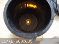
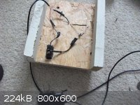
Build day #1:
I built the base out of scrap wood, drain pipe was also scrap, the electronics where all scrap from other projects aside from the yellow LED which
cost a dollar and some change. I wired a 5V 700mA cellphone charger to a 270ohm resistor after a SPST switch leading to the LED. Waiting on the
polarizing film to arrive and it should be good to test. Will update then.
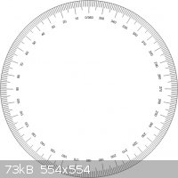
I found a print-out of a 360* 'protractor' with internal markings, that could easily be resized using an image editor and inch/cm scale rather then
pixels.
[Edited on 21-1-2012 by smaerd]
|
|
|
Arsole
Hazard to Self
Posts: 52
Registered: 21-1-2012
Location: USA
Member Is Offline
Mood: Sleepy
|
|
First Post
Looks very interesting. My other half is always telling me to toss out my old electronic equipment. Looks like I may have a future project on my
hands. 
|
|
|
alterationx10
Harmless
Posts: 4
Registered: 25-4-2011
Member Is Offline
Mood: No Mood
|
|
That looks pretty neat so far. I've built one of these, but that happen to be my website you pointed out :-)
I've never done any real measurements with that model before; I built it mainly for demonstration purposes. I would try to measure a pure sample of
one enantiomer and compare it to a literature value to get an idea of how accurate it will be when measuring with a protractor/by eye. Once you have
an idea of that, you could see if it would be good for racemic mixtures.
One idea I've had, but haven't gotten around to building it, was using a little light-intensity-to-frequency chip and a stepping motor for a detector
system. Basically put the chip behind a rotating polarizer; spin it 360 degrees. If you measure the light intensity every step, you should get
something like a sine wave, telling you when the min/max are. Do the same thing with your sample, and you can measure the phase shift to get the
amount of rotation.
As far as the cells go, you should be able to just zero out any rotation from the cuvette (i.e. running a blank). You would most likely see some
optical rotation form plastic cuvettes; probably not so much from non-specialized glass. It's been a while since I've done anything with a quartz
cuvette (too expensive considering I don't have any UV light sources), but I think it will polarize light as well; also it has some birefringence...
(not as much as calcite, for example, but it still has a little).
Anyways, I hope to see some more pictures as your project goes along!
|
|
|
smaerd
International Hazard
Posts: 1262
Registered: 23-1-2010
Member Is Offline
Mood: hmm...
|
|
Ah cool to see you on the forums!
I like the idea of the stepper motor it might get a bit tricky to keep track of the angles for the rotating plane though. If you do anything like this
or come up with any plans feel free to post them up edit - I had an idea of
using a webcamera for a computer and programming a very simple program to do very similar to what you're talking about with the light intensity
circuit. Hmm.
Still waiting on the polarizing film to ship from over seas, should be here any day though. I tidied up the wiring a bit and staple-gunned the
connections to the frame as well as put a layer of hot-glue over the screws that were near the wiring just in-case. I'll be painting the base white
tonight for aesthetics. I'll take some pictures of the results and document once I have it assembled and have it tested against an enantiomer of known
concentration.
Thanks for documenting your build and dropping by it's inspired me quiet a bit.
[Edited on 1-2-2012 by smaerd]
|
|
|
alterationx10
Harmless
Posts: 4
Registered: 25-4-2011
Member Is Offline
Mood: No Mood
|
|
Every once in a while I check the stats on my website to see where my web traffic comes from. I've known about this forum for a while, but have never
posted much (I don't post a lot on many forums, I'm more of an introvert). I was surprised to see a lot of traffic last month coming from here; what I
consider to be one of the cooler forums I lurk on!
I don't think it would be too hard to keep track of the angles. Stepper motors are used for more precise motion; every step is a predetermined angle
(based on the spec of the motor). So if you keep track of the steps, which you would have to when controlling it anyways, you are also keeping track
of the angles.
I've done some designs with a webcam, but it was for a Vis spectrometer. It was an earlier implementation, and I've made some design improvements, and
am currently working on a nice "finished package" version. I have a little PDF outlining how it works from a presentation I gave on it in a class I
took a while back, but it's over around 5mb, so I can't upload it here. I (just now) put up a link to the PDF on my site as well (in the absorbance II
page), but here is the direct link if anyone wants to check it out
http://projects.markslaboratory.com/wp-content/uploads/2011/10/Home_made_Vis_Spectrometer_vs_an_HP.pdf
I have my results along side measurements with an HP 8452A. I was a little surprised with how well it turned out. In that project, I used a camera and
took pictures with my sony cybershot on a tripod, and then did the data processing on those images on my computer. It's neat, because you can learn a
few things from a project like this like reduction of noise from data averaging, and data processing.
I have since made a program in C/C++ to automate it all using a webcam and the opencv image processing library. If you're interested in that, you can
check out the source code on my github page at
https://github.com/markslab/Spektro
You would probably need to modify it a little bit for a polarimeter, but it's not too complicated, and might be a helpful start.
I look forward to seeing your new pictures when you get them up! Maybe we can come up with some cool new plans/additions for other things.
|
|
|
smaerd
International Hazard
Posts: 1262
Registered: 23-1-2010
Member Is Offline
Mood: hmm...
|
|
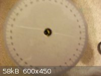
Okay so the design is complete. Now I need to figure out how to work this thing! So what I did was put markings on the tube so I knew where the light
was completely black and set the paper 'protractor' at 0* on one of these points.
The vial filled with distilled water did not change the light's direction to any appreciable degree(~1*).
Here are some pictures of the 'finished' project. The first one I took using flash the others do not have flash, the second one is at 0* the third at
90*.
  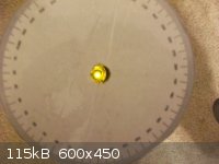
The spectrum on the light is approximately 585nm. I'm not sure if a correction is needed to fix my figures nor how to calculate it. Looked into it and
couldn't find much of anything, anyone know?
edit(fixed)- Just did a 10mL of water to 10g of sucrose and got an observed rotation of about 22*. The length of the tube(filled with water) was 5.1
cm = .51dm. The total volume of the sucrose/water solution was 15mL, so 10g of solute to 15mL solvent is (2/3)
22* / (.51dm * 2g sucrose/3mL solution) = 60.75*
The listed specific rotation for sucrose is: 66.47*
So apparently I am off by quite a bit(percent error being 8.6%).
[s]I'm not sure exactly where I'm going wrong here, going to do some more research.[/s] Then I think some more trials. Anyone see anything blatantly
wrong?
My previous edit was bad because I thought the equation called for grams solute/grams solvent which gave a really bad number lol.
Last edit- I think the main problems were rushing measurements in excitement. 8.6% error isn't terrible I'm sure it could be improved. I bet with an
increased path length this thing would be much better as well. From what I've read a 10cm pathlength is advisible(for most samples).
I'm thinking a long thin cell could be improvised with plumbing reducing adapter, some thin copper tubing, a pipe cap with a cut in it and a cut piece
of a microscope slide silicone sealanted(aquarium sealant will do the job) into place. 
Of course a long thin vial would also work but it might be easier to go this route. Could probably build something like this even very cheaply.

Might not be stainless steel but heck some rubber septum's, copper tubing and a little silicone sealant and you're in business.
Using an line of best fit and taking 3-4 measurements I imagine this thing would be fairing just fine as it is. I'll test a few more chiral molecules I have access too tomorrow after I finish some org. chem home-work.
@alterationx10 - that spectrophotometer you built is impressive! I saw other designs utilizing some kind of light to something diode and a voltmeter
on Instructables iirc.
I'd love to help chip in on any ideas you've got brewing I found some articles for DIY flourimeters . I'm not very knowledgeable when it comes to electronics but I do enjoy playing with them if the risk/reward is right
.
So many projects so little time!
[Edited on 5-2-2012 by smaerd]
|
|
|
smaerd
International Hazard
Posts: 1262
Registered: 23-1-2010
Member Is Offline
Mood: hmm...
|
|
I fixed the way I had my polarizing film. It wasn't a good idea to be setting vials directly onto something that flexible and prone to being
scratched. So I wedged it between two pieces of wood with a hole drilled in the middle and taped a microscope slide on top after testing with a level.
It was in fact, level. I could upload a picture of this 'fix' but it's pretty simplistic and probably not worth the broad-band.
Okay this time I tried it with a little bit more solution and a little more solute.
procedure
12 grams(to the 0.00g) of table sugar(sucrose) was added to to 11mL of distilled water. Supplied a little heat and stirring and a fair bit of waiting
for dissolution to occur then allowed the solution to cool. The vial was placed on the 'fixed' stand for holding the vials. It measured at 27* maybe a
little less but I have no way to quantify beyond the 1+/- degrees. I then measured the solution height in the vial it was 6.1cm = 0.61dm. The solution
was carefully poured into a graduated cylinder and it read 17.8mL. More like 18mL we'll call it.
calculations
specific rotation:
+27deg / (0.61dm * (12g/18mL)) = 66.39*+
percent error:
[|66.39-66.47|/66.47] *100% = 0.1% (too happy to care about significant figures)
conclusion:
I'm very pleased!
If you need a basic polarimeter this is the way to go! All you have to lose is like 10$. I'll be doing more tests once I find a suitable cell that is
10cm/1dm long perhaps with L-Tryptophan. I did manage to get a far better resolution though with only 1cm more in length, kind of astonishing really.
possible improvements
Use a wider section of pipe and get a 360* protractor that has increments of 0.1* .
Use a longer cell(10cm/1dm is the 'standard')
Thanks science madness for all the support along the way . Hopefully this
encourages others to try this out. Chirality is critical in organic chemistry as the many of you already know.
[Edited on 7-2-2012 by smaerd]
|
|
|
watson.fawkes
International Hazard
Posts: 2793
Registered: 16-8-2008
Member Is Offline
Mood: No Mood
|
|
Quote: Originally posted by smaerd  | possible improvements
Use a wider section of pipe and get a 360* protractor that has increments of 0.1* . |
It takes more electronics, but you can get good angular accuracy with a rotary encoder and a peak
detection circuit. The idea is that you rotate the sample continuously with a motor at constant angular velocity. Then you continuously sample the
signal and record the time of its maximum (or compute it after the fact with an A/D converter). Then you interpolate that instant with the 'ticks'
that come from the encoder. The advantage is that you are no longer limited in angular accuracy by the resolution of the encoder. It's one of the
reasons not use a stepper motor.
Error sources for this method are in the accuracy of the encoder, the quality of the peak detector, and the consistency of the friction in the rotary
bearing. Mechanically, the bearing doesn't need to be low friction inasmuch as it needs to minimize stick-slip motion, which causes noise in the
angular velocity and limits the accuracy of interpolation. The bearings used in Dobsonian telescopes are telfon-on-melamine or
polyethylene-on-melamine; these may be suitable.
Another enhancement is to use an actual sodium line instead of an approximation with an LED. Mind you, starting with an LED is a great idea, since it
lowers the cost to prototype. Low pressure sodium vapor lamps are available as low as 10W, though, and their output is almost entirely from the D line
doublet, so they've got good monochromaticity.
|
|
|
alterationx10
Harmless
Posts: 4
Registered: 25-4-2011
Member Is Offline
Mood: No Mood
|
|
Looks like you got some good results with this. Very nice!
|
|
|
Organikum
resurrected
Posts: 2329
Registered: 12-10-2002
Location: Europe
Member Is Offline
Mood: busy and in love
|
|
more information to come
| Quote: Originally posted by watson.fawkes | | Quote: Originally posted by smaerd | possible improvements
Use a wider section of pipe and get a 360* protractor that has increments of 0.1* . |
........
Another enhancement is to use an actual sodium line instead of an approximation with an LED. Mind you, starting with an LED is a great idea, since it
lowers the cost to prototype. Low pressure sodium vapor lamps are available as low as 10W, though, and their output is almost entirely from the D line
doublet, so they've got good monochromaticity. |
The latest polarimeter models virtually all use LEDs so this will be the way to go, the days of the heating-lamps are here over for good I suppose.
You may not forget that temperature is a function in the equatation and the hot sodium lamp if not very good shielded will itself distort results more
then 5nm off the sodium line. Measurements anyways can be done at different frequencies of light, simple formulas to compensate exist, so thats no
issue.
Now myself got into this polarimeter stuff and want to thank Smaerd for the work he already did and the information provided. Thoughg there might be
more out there and yes, I just requested two articles which I believe to be about exactly whats needed now: Higher precision and automated data aqusition/storage (without having to rotate
the analyser, so they claim... ).
Thats a highly interesting thing.....
regards
/ORG
[Edited on 17-12-2012 by Organikum]
|
|
|
smaerd
International Hazard
Posts: 1262
Registered: 23-1-2010
Member Is Offline
Mood: hmm...
|
|
Organikum the articles you have requested are now available. Though my crude polarimeter is decent for sugars I could not get a reading from low
concentration and short path length of L-Tryptophan. I trouble shooted and tried various simple improvised means and none were successful. Eliminating
the rotation sounds completely ideal.
I would really enjoy being able to build an acceptable polarimeter especially if it was more affordable then commercial or surplus acquired means.
Skimming through the second article(Ref 2) though it doesn't completely deliver. They require a dedicated PC(not a big deal), but a fancy lense, a CCD
camera, etc. I also think they are using an automatic polarimeter? Not too sure.
However, the other article(ref 1) looks wonderful! They claim a +/- precision of 0.5 degrees and the device looks completely manage-able. Really
appreciate the use of a worm-gear for the rotation. Much better then my PVC pipe hack job. I'd love to invest in working towards something like this,
but right now my funds are very tight and tied to other projects.
I'd really love to find a viable and reasonable resource for hobbyist parts such as gears, worm-gears, pullies, etc. I keep begging for hints about
this hoping someone will have an answer this time around.
1)Two readily-constructed instruments for the teaching laboratory
Neil S. Isaacs
J. Chem. Educ., 1983, 60 (7), p 607
DOI: 10.1021/ed060p607
2)Automatic Low-Cost Data Acquisition from Old Polarimetric Instruments Giuseppe Alibrandi, Santi D'Aliberti, Salvatore Coppolino, Antonino Villari,
and Norberto Micali
J. Chem. Educ. 2005, 82, 442.
DOI: 10.1021/ed082p442
|
|
|
watson.fawkes
International Hazard
Posts: 2793
Registered: 16-8-2008
Member Is Offline
Mood: No Mood
|
|
| Quote: Originally posted by Organikum | | The latest polarimeter models virtually all use LEDs so this will be the way to go, the days of the heating-lamps are here over for good I suppose.
|
This is true, but monochromaticity from consumer-grade LED's is not particularly good. Last I looked, and
it's been a number of years in a fast-moving field, getting sufficiently good LED's wasn't cheap. It would be be worth revisiting again, particularly
if major distributors carry them now.
|
|
|
IrC
International Hazard
Posts: 2710
Registered: 7-3-2005
Location: Eureka
Member Is Offline
Mood: Discovering
|
|
| Quote: Originally posted by smaerd | | I found a print-out of a 360* 'protractor' with internal markings, that could easily be resized using an image editor and inch/cm scale rather then
pixels. |
Do you have a link to the original image for the scale? Posting here has altered the aspect ratio.
"Science is the belief in the ignorance of the experts" Richard Feynman
|
|
|
smaerd
International Hazard
Posts: 1262
Registered: 23-1-2010
Member Is Offline
Mood: hmm...
|
|
Think this is the image at 4.5inches in diameter? - http://www.anonmgur.com/up/19c2e8de47e60d63c82c81ce8d70007f....
|
|
|
DJF90
International Hazard
Posts: 2266
Registered: 15-12-2007
Location: At the bench
Member Is Offline
Mood: No Mood
|
|
@Watson: A cursorary search has revealed the yellow LED's closest to me have a wavelength peak of 590 nm and a spectral line halfwidth (spectral
linewidth at half height) of 35 nm. Its not monochromatic by any means, but its reasonable for an operating polarimeter, and at least it's centered in
the right place for the sodium D line (589 nm).
I downloaded the first .pdf requested by Organikum a long while ago with the intention of building one, however the details are not complete in the
paper (no information given on the electronic components, specifically the resistor values and the range on (what I assume is) the microammeter, G. I
don't remember looking for a "corrections" paper though, so they may have added these details in the literature without me noticing.
[Edited on 18-12-2012 by DJF90]
|
|
|
Organikum
resurrected
Posts: 2329
Registered: 12-10-2002
Location: Europe
Member Is Offline
Mood: busy and in love
|
|
one and one is three
sometimes.
Combining the information from both articles might be the best idea - provided I have understood them correctly.
Number one rotates the polarisers at least one in the process - and they calculate the instruments resolution by the mechanical component what seems
to be the determining factor. I think they are sloppy at least, leaving out other factors as temperature and lightsources (which as I feel should be
identical and thats not proven, not even checked here).
Number two has the better approach as they have temperature control and a single lightsource and no moving parts. But a old polarimeter of a certain
kind is needed and quite some electronic which with programming will add up considerably in time and money until it runs relieably.
Number three is my suggestion and please have a look and tell me what you think:
Tada!
- Double beam but single lightsource. One or more LEDs (or even a sodium lamp for heavens sake  ) placed central, light is reflected into the tubes by mirrors. This should be easy. ) placed central, light is reflected into the tubes by mirrors. This should be easy.
- Temperature control may be added by placing the glasstube with the microscope slides as endpieces (this construct convinces me, I see superior
optical properties over other vessels plus the magic "asscheap" feature) in a tight fitting strong coppertube.The two tubes are both in the same box
filled with water or oil and one or more Peltier-elements are place in the center working on a standard temp-control circuit. Thats something what may
or may not be installed however it suits one best.
- No moving parts will be used but if I understood it right, the degree of rotation is a function of the difference of intensity of the light passing
through both tubes which resemble the two halves of the circle in the integrated instrument used in the second article. So with sufficient sensible
photodiodes (there are other electronic circuits doing maybe a better job I guess) and a simple comparator when the equatations of article two are
applied this should result in an resolution limited mainly by the quality of the optical elements of the device.
This can be buildt in steps, basic setup without temperature control and manual calculation of the rotation from the absolut readings of the
lightsensors first up to full temperature controlled automatic calibration and measurement plus data recording with an Arduino board for example, even
temperature deviation and wavelength differences when LEDs are used can be factored in, the data is known and can be used by calculation and/or a
lookup table stored in memory by the microcontroller.
Should work or did I mess something up?
Something else: Polarisation lenses are available for not to much money as camera equipment for the better models IIRC - high quality, maybe
preferable over the foil which as mentioned in article one are the optical "weakest link".
/ORG
|
|
|
watson.fawkes
International Hazard
Posts: 2793
Registered: 16-8-2008
Member Is Offline
Mood: No Mood
|
|
| Quote: Originally posted by DJF90 | | A cursorary search has revealed the yellow LED's closest to me have a wavelength peak of 590 nm and a spectral line halfwidth (spectral linewidth at
half height) of 35 nm. Its not monochromatic by any means, but its reasonable for an operating polarimeter, and at least it's centered in the right
place for the sodium D line (589 nm). |
Could you post the manufacturer, part number, and a reference to the
technical data? It would be useful for folks new to electronics to have an example of what to look for.
The main limitation of using a sodium lamp is that the D line is actually a doublet. The two peaks are about 0.6 nm apart. Thermal Doppler broadening
is much less than this. So 0.6 nm is the target to have something as good as a lamp.
Any old light source can be made more monochromatic by using a prism (or diffraction grating) and collimator to select a particular frequency range.
It works for both glow lamps and LED's. Clearly, the total luminance reduces as you throw away optical energy, but if you're going to use a
solid-state sensor anyway, the sensitivity of the human eye is more-or-less irrelevant. Frequency separation improves with distance, so if you've got
room, it's easy to separate a hot light source from the sample. This technique can easily split the D line doublet (which is readily visible even on a
student-grade spectroscope) and easily get another order of magnitude of monochromaticity.
Having said all this, you can get started with a cheap LED and get some data. I'm all in favor of amateur measurement instruments. There's no need to
hold them to a minimum level of quality sufficient for professional work. Yet it's also a bad idea to accept such compromises as a maximum expected
level of quality. A prism-based monochromator is well within the capacity of an amateur; as optical trains go, it's a pretty simple one.
|
|
|
smaerd
International Hazard
Posts: 1262
Registered: 23-1-2010
Member Is Offline
Mood: hmm...
|
|
| Quote: | | Temperature control may be added by placing the glasstube with the microscope slides as endpieces (this construct convinces me, I see superior
optical properties over other vessels plus the magic "asscheap" feature) in a tight fitting strong coppertube. |
If you do decide to go this route, ensure that the copper tubes diameter is wide enough to not interfere with the polarized light in any way. I tried
this using some scrap tubing I believe 1cm in inner diameter and it reflected the led around the tube and was worthless. I suppose the LED could have
been refined to only give a pin-hole rather then the whole size of the LED I did not experiment with this. Might be worth a try. I believe I made the
copper to glass connection using aquarium silicon by DAP. Took a few tries to get it water tight however.
| Quote: | | Polarisation lenses are available for not to much money as camera equipment for the better models |
Probably a good idea. The little plastic 'lenses' I used were very cheap, although they present a lot more error. They are flexible for one, and
though they were designed to do what they do they weren't very highly rated. It might be a good idea too look into what kind of specs polarimeters
polarizer's use. If I recall correctly there are several variables that take place in regards to polarizing elements but I forget them.
edit
All this talk about light makes me wish I took physics 3.
[Edited on 18-12-2012 by smaerd]
|
|
|
Organikum
resurrected
Posts: 2329
Registered: 12-10-2002
Location: Europe
Member Is Offline
Mood: busy and in love
|
|
LED
| Quote: Originally posted by watson.fawkes |
.....
Could you post the manufacturer, part number, and a reference to the technical data? It would be useful for folks new to electronics to have an
example of what to look for.
.... |
Available at Conrad Elektroniks the peak wavelength is 591nm, donimant is 589nm and the bandwidth is 15nm, this really should do it nicely. Not to forget the
price which is 19 Cent € what makes it somehow more reasonable then a sodium lamp with ballast what would set you back 50.- € at least
Datasheet attached
Attachment: 156229-da-01-en-LED_3mm_gelb_klar_264_7UYC_S530_A2.pdf (102kB)
This file has been downloaded 590 times
|
|
|
unionised
International Hazard
Posts: 5104
Registered: 1-11-2003
Location: UK
Member Is Offline
Mood: No Mood
|
|
The polarising / analysing filters don't need to be very good.
You could use the filters from a cheap pair of polarising sunglasses.
There's another trick that nobody seems to have mentioned. I will see if I can find a good diagram somewhere.
|
|
|
Organikum
resurrected
Posts: 2329
Registered: 12-10-2002
Location: Europe
Member Is Offline
Mood: busy and in love
|
|
| Quote: Originally posted by unionised | The polarising / analysing filters don't need to be very good.
You could use the filters from a cheap pair of polarising sunglasses.
There's another trick that nobody seems to have mentioned. I will see if I can find a good diagram somewhere.
|
Now you kept us waiting rather long, I at least would still very much like to know what trick you have had in mind?
Will you tell us?
Please?!
regards
/ORG
|
|
|
smaerd
International Hazard
Posts: 1262
Registered: 23-1-2010
Member Is Offline
Mood: hmm...
|
|
Yes please, I'd really really would like having a nice functional polarimeter without the 500$ price tag.
|
|
|
DJF90
International Hazard
Posts: 2266
Registered: 15-12-2007
Location: At the bench
Member Is Offline
Mood: No Mood
|
|
Any idea about the electronics as I mentioned above? Thats the only thing that stopped me from gathering the required part and giving it a go.
|
|
|
smaerd
International Hazard
Posts: 1262
Registered: 23-1-2010
Member Is Offline
Mood: hmm...
|
|
Well DJF I've finally had some spare time to inspect that publication more fully. The only big mystery to me is the G symbol in the circuit? Perhaps
Woelen or a EE wizard can help shine light on that?
My only other complaint with that schematic is the '10 turn helipot' which appears to be a mechanical worm-gear with some kind of potentiometer built
into it? Not really sure what thats all about or how I'd go about finding one of those.
I've actually been researching a bit more about Farraday effect polarimeters
This link has an awesome schematic: http://www.sigmaaldrich.com/etc/medialib/docs/Supelco/Genera...
Granted the photomultiplier tube would be reallly spendy I figure we could low-tech it with a cheaper detector. Although I'm not too sure about how it
actually works just yet so I'll have to do some more research.
Does anyone have access to this article:
http://www.nature.com/nature/journal/v178/n4547/pdf/1781412b...
Photoelectric Polarimeter using the Faraday Effect, E. J. GILLHAM, Nature 178, 1412-1413 (22 December 1956), doi:10.1038/1781412b0
[Edited on 3-5-2013 by smaerd]
|
|
|
| Pages:
1
2
3
..
9 |


