| Pages:
1
2
3
4
..
9 |
DJF90
International Hazard

Posts: 2266
Registered: 15-12-2007
Location: At the bench
Member Is Offline
Mood: No Mood
|
|
Component G is a microammeter I expect. What bothers me is the values of the two resistors, R1 and R2. If I knew that I could potentially build one of
these once I have the other required components.
Attachment: Photoelectric polarimeter.pdf (243kB)
This file has been downloaded 501 times
|
|
|
smaerd
International Hazard
Posts: 1262
Registered: 23-1-2010
Member Is Offline
Mood: hmm...
|
|
Doesn't it seem weird to have the micro-ammeter directly hooked up to the two detectors? I'm pretty certain the right hand side of the schematic + and
- leads are where the micro-ammeter connects. The resistance values will depend on the photo-detector and amplification circuits out-put. Other-wise
the microammeter might be 'underwhelmed' or 'overwhelmed'. That's atleast my understanding. The G must then be the generator?
Although the circuit diagram is not laid out very similar to the actual instrument(probably because it has the power supply circuit inside of it). It
appears as though this "G" is some kind of amplifier circuit from some kind of photo-detector? Maybe it stands for "generator" or something. Weirdly,
at least weird to me is that it seems as if both photo detectors are in series and are represented by "PR1" and "PR2". Though typically when a
polorizer is referred to as an analyzer it simple means it's the second polarizer and has nothing to do with a detector. It's a bit strange they make
no direct mention of the detectors used.
I'm really more interested in this farraday effect polarimeter simply because it involves no rotating mechanical parts. I'm keen to research this much
more in depth, could be an arduino project.
[Edited on 4-5-2013 by smaerd]
[Edited on 4-5-2013 by smaerd]
|
|
|
watson.fawkes
International Hazard
Posts: 2793
Registered: 16-8-2008
Member Is Offline
Mood: No Mood
|
|
I assume you all are talking about the article "Two Readily-Constructed Instruments for the Teaching Laboratory".
The "G" stands for galvanometer. You need one that stands in the center at zero, because current can flow either way.
Understanding how these circuits work requires understanding how a Wheatstone bridge works. That term is mentioned twice in the article, incidentally. You really don't need to be told the resistor values once you
understand it. Unless you can source exactly the same photoresistors (that's what PR stands for) as they use you'd likely need to change the values anyway. You'll also see LDR (light-dependent
resistor) used for the same part.
The "10 turn helipot" refers to a particular mechanism used for potentiometers (variable resistors). If you've got a deep electronics junk box (as the
audience of this article generally would), you'd have one lying around. Stripping away the scavenging aspect, it's a worm gear driving a spur gear
used to get high resolution angular positioning. Seems like angular accuracy might be much less. Other ways of doing reduction gearing could
accomplish the same result.
|
|
|
unionised
International Hazard
Posts: 5102
Registered: 1-11-2003
Location: UK
Member Is Offline
Mood: No Mood
|
|
Quote: Originally posted by Organikum  | | Quote: Originally posted by unionised | The polarising / analysing filters don't need to be very good.
You could use the filters from a cheap pair of polarising sunglasses.
There's another trick that nobody seems to have mentioned. I will see if I can find a good diagram somewhere.
|
Now you kept us waiting rather long, I at least would still very much like to know what trick you have had in mind? 
Will you tell us?
Please?!
regards
/ORG |
Oops!
I forgot about this (and I couldn't find a pic on the web)
[Edited on 5-5-13 by unionised]
|
|
|
unionised
International Hazard
Posts: 5102
Registered: 1-11-2003
Location: UK
Member Is Offline
Mood: No Mood
|
|
Take a polariod filter- you can tell this one is really trashy 'cos you can't read through it.
Cut it in half.
Cut a diagonal sliver off one half and put the two pieces together.
tape them to a bit of glass to get a "split field analyser".
(One of the pictures is missing from the last post so I have added it here)
The idea is that you rotate the analyser until the two parts are the same brightness.
It's easier to judge that exactly than to find the minimum transmission.
(I had to mess with the pictures a bit because the camera's auto-exposure doesn't cope well but I think you can get the idea. )
[Edited on 5-5-13 by unionised]
[Edited on 5-5-13 by unionised]
|
|
|
smaerd
International Hazard
Posts: 1262
Registered: 23-1-2010
Member Is Offline
Mood: hmm...
|
|
Or a "half-shade" polarimeter looks very simple and then there is no need for a reference beam.
Theory of Using a Photoelectric Detector with a Half-Shade Polarimeter, Dan Mathews
Applied Optics, Vol. 4, Issue 6, pp. 761-762 (1965)
http://dx.doi.org/10.1364/AO.4.000761
(attached)
Something still is drawing me to the faraday modulator maybe just for the challenge and to learn more about optics. Seems to have some practical
limitations though.
Attachment: polarimeter1.pdf (517kB)
This file has been downloaded 815 times
|
|
|
DJF90
International Hazard
Posts: 2266
Registered: 15-12-2007
Location: At the bench
Member Is Offline
Mood: No Mood
|
|
Cheers for your input watson. I've built a wheatstone bridge before so I should know this, but it was a long while ago. I'll go refresh my memory.
Thanks again.
|
|
|
smaerd
International Hazard
Posts: 1262
Registered: 23-1-2010
Member Is Offline
Mood: hmm...
|
|
Alright so I've thought about it and I think what I'm going to do is build an automatic polarimeter. Can't figure out the worm-gear potentiometer
thing and figure if I'm spending money on it I might as well make it nice.
Was thinking servo's but I don't think they would provide enough resolution.
edit - alright no need for an automatic polarimeter my friend with EET experience talked me down. Too expensive and mechanical has been the standard
for centuries(?) now.
[Edited on 10-5-2013 by smaerd]
|
|
|
watson.fawkes
International Hazard
Posts: 2793
Registered: 16-8-2008
Member Is Offline
Mood: No Mood
|
|
| Quote: Originally posted by DJF90 | | Cheers for your input watson. I've built a wheatstone bridge before so I should know this, but it was a long while ago |
The Wheatstone bridge is a basic technique of electronics for instrumentation. The basic principle, one which extends beyond this
circuit, is nulling. When there's no current through the resistor in the middle (the only one not connected to a terminal), what it means is
that the voltage divider on one side divides in the same proportion as the one on the other side does. It's how you compare the reference beam to the
beam-with-absorption; a variation on the null is used in the paper. The same basic topology is also the traditional way of doing absorption
spectroscopy, including IR, visible, and UV. | Quote: Originally posted by smaerd | | Can't figure out the worm-gear potentiometer thing [...] Was thinking servo's but I don't think they would provide enough resolution.
|
You don't need to use the same worm-drive mechanism. Any speed reducing gear train would would. It's exactly
such a gear train that's used in those little RC servos. I found what looks like a good source of inexpensive plastic gears for such a gear train at
Gizmo's Zone; in particular, they have the compound gears (two gears molded together on single axis) that a number of other vendors don't seem to
carry.
|
|
|
smaerd
International Hazard
Posts: 1262
Registered: 23-1-2010
Member Is Offline
Mood: hmm...
|
|
Okay so against the good advice I've been given I can't let go of the automatic polarimeter allure. I'm thinking about using a pulley drive and a
stepper motor to get the resolution I desire. I realize the instrument would fall out of calibration rather easily but programming a calibration
routine shouldn't be too hard. Rotate until black rotate the other way until black again, compare photoresistor values at half way point, etc.
The idea is this, use a 1.8* step, stepper motor. Tack on a 6mm diameter timing belt pulley. Have this run to a rotor with a ~80mm pulley directly, on
the other side of the rotor fix on a 16mm timing belt pulley and have this drive another 80mm timing pulley. The rotor for the second 80mm timing
pulley will be a hollow brass-tube so wires for an LED light can go through. The face of the gear will be fixed with a short length of PVC tubing with
a polarizing filter on-top. The bearings for the rotors will be simple sleeve bearings and a good deal of nice thick grease. This if my calculations
are correct bring the 1.8* step to a ~0.03* step. I based this on the notion that the arc-length of the original positions of a pulleys to their
rotated state should be equal. Thus:
1.8deg * (6mm/80mm) * (16mm/80mm) ~= 0.03deg
The design from there on is pretty simple and based on the favored schematic discussed above. A second reference LED, photo-resistors, etc. My only
twist on the electronics is to use an arduino to process the data rather then a wheat-stone bridge. I figure it'll be easier for me to actually see
what is happening as I'm more programming oriented. Perhaps it'll be better for handling noise anyways. 25 dollars for an arduino isn't exactly
breaking my budget anyways, especially if there is an opportunity for an automatic polarimeter with hopefully good resolution(aiming for 0.03* angular
resolution) and potential for a legitimate digital display or direct computer data acquisition.
I do have some questions for the more engineering inclined members.
Would the error from a stepper motor(typically 5% "non-accumulative") be a huge burden here after it goes through the timing belt pulley mechanism? I
tried looking into gear and pulley error calculations and it seemed incredibly cumbersome, but saw a few robotics experts using these components for
what seemed to me like high-precision work so it seems viable. Then again looks are often so deceiving...
The other is, would sleeve bearings work for this application? I figure greased brass on slippery plastic at low speeds and low load there should be
no issue, but if a more experienced builder had a gut feeling about it I'd like to be educated.
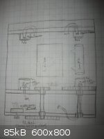
Anyhow here's the basic mechanical schematic I've worked out so far. Haven't touched the electronics aspect too much yet but I don't think that is
where I'll be struggling the most.
[Edited on 25-5-2013 by smaerd]
[Edited on 25-5-2013 by smaerd]
|
|
|
watson.fawkes
International Hazard
Posts: 2793
Registered: 16-8-2008
Member Is Offline
Mood: No Mood
|
|
| Quote: Originally posted by smaerd | I'm thinking about using a pulley drive and a stepper motor to get the resolution I desire. I realize the instrument would fall out of calibration
rather easily but programming a calibration routine shouldn't be too hard. Rotate until black rotate the other way until black again, compare
photoresistor values at half way point, etc.
[...]
My only twist on the electronics is to use an arduino to process the data rather then a wheat-stone bridge. I figure it'll be easier for me to
actually see what is happening as I'm more programming oriented. Perhaps it'll be better for handling noise anyways. |
I really would not use pulleys, but rather a gear train. The gear trains I posted up-thread look like they'd work fine. You'll get a
lot of errors with a pulley, not just cumulative ones, but jitter noise from stick-slip friction. In other words, it's a mechanical source of noise.
This particular application can make good use of a gear train because there's no need to ever rotate but a single direction. This eliminates issues
with backlash. Suitably gearing down the motor reduces angular error on the drive shaft by the gear ratio. The encoder error will get reduced by the
step-down gear ratio, and it's fairly easy to get a gear ratio high enough so that the angular error on the position of the gear teeth is the dominant
source of mechanical noise.
You'll do much better with accuracy by using a servo on the drive shaft than a stepper. A servo is just a motor with an encoder. The encoder gives you
an explicit measurement rather than relying upon the implicit measurement of a "step". In olden days, you might have needed some time to take a
measurement while a stepper motor was in its dwell state (i.e. not moving). There's no need to stop the motor for this kind of measurement.
The digitization speed from a modern A/D converter, even a cheap one as is on the Arduino, is a lot faster than the mechanics. Such a device would
just rotate continuously and spit out a continuous stream of data. The digitization rate depends on whether you want to process data on the Arduino or
on a host machine. The new Leonardo uses a microprocessor with on-board USB, which means that getter a big stream on data onto a PC is much easier.
Furthermore, you can use a servo mechanism, but you don't need a servo controller, that is, a closed loop rotation speed controller, since all you
care about is angular position, not rate. Open loop control for this is simple; it's just a constant voltage. (Use the old standby LM317 to make an
adjustable DC supply for the motor.)
Digitizing the data does not preclude use a Wheatstone bridge; it is a complementary technique. A Wheatstone bridge is a step toward a differential
measurement (comparison to a reference), a technique that's always more accurate than an absolute measurement. You really want a reference beam of
some sort so that you can subtract off its signal appropriately. Look up, for example, the term common mode rejection ratio (CMMR) for an introduction. For example, if the illumination beam is split into two paths, then luminance variations
(from power supply variations) can get subtracted off easily.
|
|
|
smaerd
International Hazard
Posts: 1262
Registered: 23-1-2010
Member Is Offline
Mood: hmm...
|
|
Really, really, appreciate the insight. All of my whacky projects and knowledge bank have benefited from your input.
Gears are much cheaper anyways. I think the problem was I was basing most of my information off of precision timing pulleys and belts($$$), woops!
I'll still need to figure out a good way to mount them all but that shouldn't be too much of a challenge. A couple of those compound gears for example
an 8:60 stacked on top of one another should do the job nicely. I'll have to figure out a way to get the LED mounted on the final gear face without
twisting and pulling wires into the gear's over time but I'll think about that today should be a relatively easy problem to solve.
Ah, I see what you're saying now! Hack a conventional servo, and focus on velocity for positional measurements? Using something like this(because I am
lazy and prefer off the shelf components) - https://www.sparkfun.com/products/9347 ? That's a pretty slick work around.
I see what you're saying about the wheat-stone bridge. I have an unacceptable tendency to look at circuit diagrams and get scared. This will be a good
project to conquer that.
So you're saying I should use two power supplies? One for the lights and arduino, and one for the motor. That's reasonable. I'll probably need to use
a dedicated computer for the Leonardo board which I purchased for this project. It's likely too much data to handle(positional calculations and the
resistance measurements) on the 32kb drive(4kb dedicated already). Unless I popped on a SD card adapter.
Found a good tutorial for the PSU: http://jumperone.com/2011/08/lm317-adjustable-psu/
[Edited on 25-5-2013 by smaerd]
|
|
|
watson.fawkes
International Hazard
Posts: 2793
Registered: 16-8-2008
Member Is Offline
Mood: No Mood
|
|
| Quote: Originally posted by smaerd | I'll have to figure out a way to get the LED mounted on the final gear face without twisting and pulling wires into the gear's over time
[...]
Hack a conventional servo, and focus on velocity for positional measurements? Using something like this(because I am lazy and prefer off the shelf
components) - https://www.sparkfun.com/products/9347 ?
[...]
So you're saying I should use two power supplies? One for the lights and arduino, and one for the motor. |
You only need the polarizer to move. The light source can remain in place. I don't know offhand where to get them, but a ring gear
with a big hole in the middle seems ideal for this.
The servo you referenced is the general kind I'm thinking would work. It has a motor, a gear box, an encoder of some form, and a control board. This
particular one, however, if my cursory reading of the data sheet is right, doesn't have an encoder output that comes out on the connector. You need
such a signal in order to read out the angular position. You might be able to hack the control board to extract it (if it's there). Probably better is
to find out that already has it.
You'll certainly need a separate supply for the motor, since you should always separate a motor supply from the digital supply. I mentioned using an
LM317 for it. This is only if you decide that you need adjustable motor speed; you may decide that you don't need it. On the other hand, it's an easy
thing to set up during the prototype to see if you want it. If you decide you need motor speed control, a pulse-width modulation scheme might by more
appropriate.
You may _also_ want a separate supply circuit for the LED. It depends on whether there's enough supply noise to care or not. The digital components
will be more tolerant of supply noise than an LED will. If it matters, you want a constant-current supply (which you can get with a current mirror
made with two transistors) and you may want a low-pass filter on it (a simple LC filter, for example).
|
|
|
smaerd
International Hazard
Posts: 1262
Registered: 23-1-2010
Member Is Offline
Mood: hmm...
|
|
The problem is once you make a servo open loop(continuous rotation) there is no more angular position readings. All that is is a commercial servo
hacked for continuous rotation. I could do the hack myself but I'm not sure how I could get an angular reading on it don't think it's possible.
[Edited on 26-5-2013 by smaerd]
|
|
|
watson.fawkes
International Hazard
Posts: 2793
Registered: 16-8-2008
Member Is Offline
Mood: No Mood
|
|
| Quote: Originally posted by smaerd | | The problem is once you make a servo open loop(continuous rotation) there is no more angular position readings. All that is is a commercial servo
hacked for continuous rotation. I could do the hack myself but I'm not sure how I could get an angular reading on it don't think it's possible.
|
If it's called a servo, it has an angular encoder in it somehow; it's part of the definition. In this
application we don't need the encoder as part of a closed-loop control to adjust the speed finely. All we need the encoder for is to sense position so
that it can be digitized. This isn't the ordinary mode for hobbyist servos, so it may take a little digging to find a COTS model that fits.
|
|
|
smaerd
International Hazard
Posts: 1262
Registered: 23-1-2010
Member Is Offline
Mood: hmm...
|
|
http://letsmakerobots.com/node/18615 here's a solution the magnetic encoders
aren't really ideal though.
[Edited on 26-5-2013 by smaerd]
Thought about it and yea I'm going with a stepper motor. Servo's are good for what they do but steppers are way more affordable. Industrial servos for
precision measurements use absolute optical encoders. Way out of my price range.
http://www.phidgets.com/products.php?category=23&product...
45$ but its about as good as it gets. Would need a controller but I'll figure something out .
Or if I could figure out what kind of gear train laser printer assemblies use that would be even cheaper!
Something like this:
http://www.allelectronics.com/make-a-store/item/SMT-107/STEP...
[Edited on 26-5-2013 by smaerd]
|
|
|
watson.fawkes
International Hazard
Posts: 2793
Registered: 16-8-2008
Member Is Offline
Mood: No Mood
|
|
| Quote: Originally posted by smaerd | Industrial servos for precision measurements use absolute optical encoders. Way out of my price range.
[...]
Or if I could figure out what kind of gear train laser printer assemblies use that would be even cheaper! |
"Absolute optical encoders" are what old-style mechanical mice used to use, one on each axis. I used to see lots of projects that
reused of their guts with printed radially-marked wheel that ran through the optoelectronic element.
I posted a link to an inexpensive gear train above.
|
|
|
arsphenamine
Hazard to Others
Posts: 236
Registered: 12-8-2010
Location: I smell horses, Maryland, USA
Member Is Offline
Mood: No Mood
|
|
Minor correction: these were
free-running slitted wheels using a pair of interruption optocouplers to generate quadrature output. The output is called incremental or relative
motion.
An alternative is a middling stepper motor mated with one of these encoders on the shaft. Vanilla steppers move 1.8 degrees per step; that can be
reduced using a lead screw with a pitch between 4:1 and 10:1, equivalent to 800 and 2000 steps per inch travel, respectively. Additionally, modern
stepper controllers operate in half, quarter, and tenth step modes for even higher resolution.
Obviously, incremental encoders obligate a "home" limit sensor on whatever it is you're moving.
If you want to "hand roll" a slotted wheel for your encoder, you can gen one up in Postscript and print it out on a clear plastic sheet.
Alternatively, print it as a resist pattern on copper foil that's glued to a glass or plastic disc.
Myself, I'd say fukkit (with considerable asperity) and just buy the stepper with mated encoder for ~$100 and be done with it.
|
|
|
smaerd
International Hazard
Posts: 1262
Registered: 23-1-2010
Member Is Offline
Mood: hmm...
|
|
I realize I can not know the absolute angle of my object gear without a really nice encoder. Though, is there a reason why I cannot do the following.
Use a geared down stepper motor. Say ~0.018* per step with 5% accuracy with a 12 tooth pinion gear mated with a 96 tooth object gear. So 0.018*
(12/96) ~ 0.00225* degree angle change on the object gear(the one with the LED and polarizer mounted). Then only move in one direction so there is
little back-lash. Then program a calibration routine(without any sample) such that, the motor is rotated until it finds a dark region. The
micro-controller would then find the half-way 'point' of one of these dark-regions and calculate how many steps to get there. Or if I have this hooked
up to a computer I could use a statistical mean or standard deviation of the measurements taken in this region. Then the stepper motor will step its
way along slowly(slow means less chance of missing steps). From this point the sample could be inserted and an ordinary polarimeter scan routine could
be performed. Counting steps and checking for intensity of light through the wheat-stone bridge and photo-resistors etc.
With such a small geared down 'step' on the object gear even if the routine was off by 90% of a whole step(+/-0.002*) the end result would still be
more than sufficient to give a great readout for any sample. In general for chemical applications 2 decimals is more than sufficient.
I just don't see why I would need to use an encoder when I have essentially an optical detector that I will be using already to take positional
measurements. Of course, ideally I would be keeping track of the absolute angle, but even still using such a method I would need re-align the motor at
each power up in-case it was moved or stopped during a half-run(mechanical failure), etc.

[Edited on 27-5-2013 by smaerd]
Edit again - I also think a reverse biased PIN photodiode would provide better resolution then a photoresistor. They aren't too expensive either.
http://www.digikey.com/product-highlights/us/en/marktech-opt...
[Edited on 27-5-2013 by smaerd]
[Edited on 27-5-2013 by smaerd]
|
|
|
watson.fawkes
International Hazard
Posts: 2793
Registered: 16-8-2008
Member Is Offline
Mood: No Mood
|
|
A few purchasing links from servocity.com. These are parts that would allow a polarizer to be mounted in the bore of a gear, which was driven from the
outside by a gear motor.
Gear motors, from 0.5 rpm to 303 rpm, 6mm shaft. If it's possible to swap out the electric motor in one of these with a double-ended shaft version
(need to call supplier), then you can put an encoder on the back shaft and leave the gearbox on the front one.
Pinion gears, 32 pitch, 6 mm bore, 16T - 32T. Used on the gearbox shaft.
1 inch bore gears for hub mounting, 32 pitch, 76T - 128T. One inch bore should be enough for both a reference beam and a standard 12.5 mm wide
cuvette. Given the hole patterns, you could also bore out the gear for a larger optical path if necessary. You can build an adequate hub out of PVC
pipe and mount it as a bushing.
If you picked a 100T ring gear (plenty of optical path), a 32T pinion, and a 3 rpm gear motor, it will take slightly more than a minute to make a
360° revolution and to gather all the data possible with any optical train. Assuming that you digitize at a rate of 6 kHz with a 1 rpm
polarizer rotation, you're taking one sample every thousandth of a degree. If you're digitizing at 12 bits (say), you're still at less than a megabyte
of data to analyze and the data rate is still rather low by USB standards. Given that accuracy is proportional to the square root of the number of
samples, you can easily get another 2 or 3 digits of accuracy by decent numerical processing, since you can match on either side of the peak at every
signal level. So even if you lose a digit or two because of mechanical sloppiness, you'll can get at least three decimal digits of ultimate accuracy,
enough that other sources of error would come to predominate.
| Quote: Originally posted by arsphenamine | | Minor correction: these were
free-running slitted wheels using a pair of interruption optocouplers to generate quadrature output. The output is called incremental or relative
motion. |
True; I was being sloppy about language. The utility of this technique, though, is that it affords a
fairly precise angular signal all by itself. The gear ratio of the gear box inside that 3 rpm motor is 1000:1, which means the motor is running at
3000 rpm, or 50 revolutions per second. An encoding wheel with 400 marks (a pretty easy target with photographic techniques) would give a native pulse
signal at 20 kHz. 400 marks at 0.5 mm feature size gives a wheel about 2.5 inches in diameter. You could phase-lock a trigger oscillator to this
signal pretty easily and use it to trigger digitization events. (The phase locking will average out variations in the marks as well.)
One advantage of using an encoder and a free-running motor is that you can completely eliminate all the circuitry and software to drive a stepper
motor. While I haven't done an exact cost analysis, I have to imagine it's cheaper just it parts count to use this kind of explicit encoder rather
than rely on the construction of a stepper motor to provide an implicit one.
Edits: typos. arithmetic.
[Edited on 2013-5-27 by watson.fawkes]
|
|
|
smaerd
International Hazard
Posts: 1262
Registered: 23-1-2010
Member Is Offline
Mood: hmm...
|
|
Yea I was planning on building the gear train from servo-city parts specifically because they had nice 'channels' pre-made mounts, bearings, hollow
shafting, etc. I won't be fixing the sample to the rotating polarizer I think you knew that but wanted to be clear.
I found these - http://www.robotmesh.com/optical-shaft-encoder-2-pack?gclid=... 90 ticks per revolution.
More on those:
http://content.vexrobotics.com/docs/instructions/276-2156-in...
Alright I'll be looking into optical encoders now. I'm just a bit confused about the topic in general. Edit - I see now. Optical encoder seems like
the way to go.
Okay I made up a little excel sheet just to simplify the calculations(uploaded them just to save anyone else any time if they are following along).
I'm sure I could have actually set up a series of equations and worked out a matrix or some crap but this will do fine. You're right watson this is
the easiest and likely most affordable way to go about it. Seems like the only trick is finding a sufficiently slow motor so it can be gear reduced.
For example this motor+encoder package would work but even with another gear reduction it would go probably too fast(~8rpm). So a bit more hunting
around.
http://www.dfrobot.com/index.php?route=product/product&p...
Actually I could just starve the motor of a bit of power to slow it down a bit. For some reason I was thinking that the RPM's were linked to the
encoder hahaha. Need to embed in my mind that this is not a stepper motor.
Thanks again watson!
Attachment: Encoder calculator.xls (8kB)
This file has been downloaded 421 times
Attachment: Encoder calculator.ods (15kB)
This file has been downloaded 406 times
[Edited on 27-5-2013 by smaerd]
[Edited on 27-5-2013 by smaerd]
|
|
|
watson.fawkes
International Hazard
Posts: 2793
Registered: 16-8-2008
Member Is Offline
Mood: No Mood
|
|
I corrected some of the
figures I used in my previous post; some of my arithmetic was wrong. Rotation at 8 rpm instead of 1 rpm, using the same sampling rate, reduces the
data by a factor of eight. The resolution of the encoder is 64 counts per revolution (CPR), instead of the 400 I used to estimate. So you'd lose some
accuracy, but even so it's still pretty good.
Frankly, though, at just $30 for the motor + encoder + gear box, it's a bargain. It would eliminate a large number of mechanical troubles involving
getting to a first working prototype. Most of your time is going to be spent elsewhere anyway, in electronics and software. Even if you decide to
replace this unit with something else, it'll get you going for pretty cheap.
|
|
|
smaerd
International Hazard
Posts: 1262
Registered: 23-1-2010
Member Is Offline
Mood: hmm...
|
|
Alright so I finally have the mechanical aspects all figured out I think. So I've been stepping in to studying the electronics and what I'll have to
be doing. So I won't be using the galvanometer in the wheat-stone bridge obviously, and instead I will be using the arduino to measure the voltage.
Sure I'd like to know the current as well and all of that but the voltage is good enough as the measurement is relative and obviously V=IR is a direct
relationship.
Here's a good link about how to use an arduino to make accurate voltage readings.
http://hacking.majenko.co.uk/making-accurate-adc-readings-on...
I think I will also be using the standard arduino 3.3V pin (which fluctuates) as a PSU for the LED's. I realize there will be ripple and such but at
the same time the wheat-stone bridge should take care of this on the measurement end? I could also smooth it out with a capacitor or something. That
way I only have two plugs for this thing. One for the motor PSU and one for the arduino(USB).
I figure the motor will be powered by a wall-wart and the smoothed through a LM317 voltage regulator circuit. Perhaps with the load it will be a bit
slower anyways. Maybe I'll go by way of PWM to slow it down. Hard to say. I'd like to put a bipolar capacitor on the motor pins but I believe the
encoder will block this from happening. So be it.
Biggest concern right now:
I am a bit worried about asking for too much from this arduino as it will be have to be taking a lot of measurements at once. Primarily with the
quadrature encoder on the dc motor. I've calculated that at 5RPM on the object gear
(data for using this motor:http://www.dfrobot.com/index.php?route=product/product&path=47_110&product_id=633#.UaPHEc4u7Cc with another 16Tooth
pinion gear driving a 100Tooth object gear)
R.P.M.: 5.28
Pulses Per Revolution:52400.0(motor shaft)
Δθ(◦ ) per pulse: 0.006870229(object gear)
Time for one Rotation(s): 11.3636363636(object gear)
Time for one pulse(s): 0.0002168633
Time for one pulse(ms): 0.2168632894
From this link someone measured the maximum transfer rate of an arduino leonardo
http://forum.arduino.cc/index.php?PHPSESSID=mclufkt52rhbep7o...
| Quote: | | Leonardo transfer rate at 39258 bytes/second |
or 39.258 bytes per milisecond, or 0.0254 miliseconds per 1 byte. So it seems like I might be able to make this happen but I need to remember I will
also be measure voltage on this same micro-controller simultaneously. So I should probably find a way to slow down the motor at least by a factor of
about 10?
[Edited on 2-6-2013 by smaerd]
Edit - okay I'm learning a bit more about how this all works. I see someone has used an 8bit atmega chip to control two motors with 3000 pulses per
rotation at a relatively high-speed. So I may need to factor in some sort of motor controller here. I don't care if I am getting one reading in 5
minutes to be honest but the 11 second revolution is clearly too fast. Going only one direction helps here to simplify things a lot. Lots more to
learn here with the soft-ware and hard-ware. Essentially I'll need to use an interrupt routine.
I realize it may seem a bit cumbersome for me to sort of plog what I'm thinking about but I find it pretty beneficial and figure if anyone is reading
they can interject and hopefully stop me from wondering down some wrong roads of thought. hehehe.
[Edited on 2-6-2013 by smaerd]
[Edited on 2-6-2013 by smaerd]
|
|
|
watson.fawkes
International Hazard
Posts: 2793
Registered: 16-8-2008
Member Is Offline
Mood: No Mood
|
|
First things first. | Quote: Originally posted by smaerd | | I realize it may seem a bit cumbersome for me to sort of plog what I'm thinking about but I find it pretty beneficial and figure if anyone is reading
they can interject and hopefully stop me from wondering down some wrong roads of thought. |
Using the Leonardo
may not give you all the performance you want. Regardless, it will give adequate service. More importantly, it has enough to get started. This is
definitely a project where getting version 1.0 finished it important. So in general, if you have to dial down performance to make it work, just live
with it. Higher performance will require more work, but more importantly, you need to understand where to put that work so that it's not wasted, and
that's why version 1.0 is important.
At some point you'll need an error model. That's a mess of algebra that allows you to weigh the quantitative effect of one noise source against
another.
| Quote: Originally posted by smaerd | Here's a good link about how to use an arduino to make accurate voltage readings. [...]
I think I will also be using the standard arduino 3.3V pin (which fluctuates) as a PSU for the LED's. I realize there will be ripple and such but at
the same time the wheat-stone bridge should take care of this on the measurement end? [...]
I figure the motor will be powered by a wall-wart and the smoothed through a LM317 voltage regulator circuit. Perhaps with the load it will be a bit
slower anyways. Maybe I'll go by way of PWM to slow it down. Hard to say. [...]
I am a bit worried about asking for too much from this arduino as it will be have to be taking a lot of measurements at once. [...]
So it seems like I might be able to make this happen but I need to remember I will also be measure voltage on this same micro-controller
simultaneously. So I should probably find a way to slow down the motor at least by a factor of about 10? |
One
of the advantages of this design, i.e. taking measurements and locating a maximum, is that you don't ever need to know the absolute voltage.
All you're ever doing is comparing one reading against another; at no point does the precise voltage that generated the reading matter. So the link
you posted is more-or-less irrelevant to the current project.
On the other hand, you do want to ensure that (1) the voltage reading are consistent from sample-to-sample and (2) you're sensing at close to the
maximum dynamic range of the A/D converter. For both of these, you need to know about the AREF pin (Analog REFerence), by which you can set the
maximum signal expected. Because you're sensing a difference in extinction readings, which isn't going to be very large, the voltage difference in the
bridge might never be very high. I can think of three techniques to address this. (a) Use an op-amp as a buffer and amplifier to move the signal you
have into a more friendly range. You may want to do this anyway, even if your gain is exactly 1. (b) Increase the voltage on the sensing bridge to
increase the voltage difference. Not hard, but requires another power supply. (c) Provide a lower reference point with AREF. This only requires a
voltage divider, say, a pair of resistors to get in the ballpark and a trim potentiometer to set an exact point.
If you want to slow down the motor, use PWM. Your torque will be much better that way, since it's a DC motor. Since you don't need variable PWM but
rather just a fixed speed, it would be easy to use an external chip to make the drive signal. Putting it inside the microprocessor reduces parts count
at expense of performance. Your call.
Not only do you want a separate supply for the motor, you also want to put an optoisolator on the digital output from the microprocessor. You can get
noise propagating backward through the output pin otherwise. Not strictly necessary for version 1.0, but desirable. Use of an optoisolator is
recommended regardless of whether you're generating pulses on the microprocessor or just an enable signal (to turn the motor on).
The link you posted for data rate is for serial output. I don't have a definitive answer, but sending data out the USB interface is going to be
faster. In any case, my surmise is that the limiting rate is the A/D converter, not the output speed.
Finally, I'll reiterate that getting to version 1.0 is what's important. Version 1.0 probably has all its electronics on a breadboard. Once you've got
that, then you'll have a solid feel for how to develop an error model and more importantly, why to do so.
|
|
|
smaerd
International Hazard
Posts: 1262
Registered: 23-1-2010
Member Is Offline
Mood: hmm...
|
|
Thanks woelen. Yea it should be a relative reading rather then anything near absolute. That'll help a lot code-wise too. Thanks again seriously.
I'm taking the financial plunge. Figure if it costs around 200 bucks I'll learn more by doing this then I would by taking a course at a college
campus. Worst come to worst I'll have some awesome parts for other projects as well.
I got some 590nm 3500mcd LED's from superbrightleds.com . Have to make a warning that these suckers are bright! Think they'll do much better then the
rinky dinky LEDs I was using in my previous polarimeter(from radioshack). I may consider a prism monochromator for the opitical train later on down
the line. Optical grade(nonquartz as this is visible light) prisms are very affordable(10 USD or so). For version 1.0 though these should suffice and
definitely didn't break the bank.
My next post will be with some semblance of progress and hopefully a fair amount less uncertainty.
|
|
|
| Pages:
1
2
3
4
..
9 |


