| Pages:
1
2
3
4
5
6
..
9 |
smaerd
International Hazard

Posts: 1262
Registered: 23-1-2010
Member Is Offline
Mood: hmm...
|
|
Alright new detector in(BPW-21 rather then the BPW-34), new LED in. when the LED is up close I get great readings(in the 100-200 arbitrary units
range). That wasn't possible with the old set-up. From farther away(15cm) I am getting crappy readings. Thinking I need to focus this LED. It's
significantly brighter but, probably still too diffuse. Kind of frustrating being able to see the detector illuminated from behind the polarizing film
but get a 0 reading. Shooting the light down the steel tube probably doesn't help much either.
I probably need to increase the resistive load some... Thinking about upping the power supply to 12V to the op-amp(back to three power supplies I
guess). 5V is probably just too low for this. We'll see what a 10kOhm, 20kOhm, and 50kOhm do. Right now the 2.2KOhm is probably way too low.
[Edited on 8-9-2013 by smaerd]
|
|
|
bfesser
Resident Wikipedian
Posts: 2114
Registered: 29-1-2008
Member Is Offline
Mood: No Mood
|
|
Forgive me if this is a stupid question, but why not just use a laser diode?
|
|
|
DJF90
International Hazard
Posts: 2266
Registered: 15-12-2007
Location: At the bench
Member Is Offline
Mood: No Mood
|
|
Wrong wavelength, at least for measuring "standard" optical rotations. I'm not sure if theres formulae for wavelength correction, i.e. take the
measurement at 690 nm, but can convert the reading to what would be observed at 589 nm.
|
|
|
bfesser
Resident Wikipedian
Posts: 2114
Registered: 29-1-2008
Member Is Offline
Mood: No Mood
|
|
Wow. I had no idea that 589 nm lasers were so expensive.
|
|
|
IrC
International Hazard
Posts: 2710
Registered: 7-3-2005
Location: Eureka
Member Is Offline
Mood: Discovering
|
|
While I have accumulated dyes and optics I have yet to build a tunable dye laser. Would it be fairly cheap to construct one for 589 nm using Sodium
Fluorescein or similar dye? Plans are not too hard to find on the subject of dye lasers.
http://www.repairfaq.org/sam/lasercdy.htm
http://www.technology.niagarac.on.ca/people/mcsele/lasers/La...
"Science is the belief in the ignorance of the experts" Richard Feynman
|
|
|
watson.fawkes
International Hazard
Posts: 2793
Registered: 16-8-2008
Member Is Offline
Mood: No Mood
|
|
Quote: Originally posted by smaerd  | | Alright new detector in(BPW-21 rather then the BPW-34), new LED in. when the LED is up close I get great readings(in the 100-200 arbitrary units
range). That wasn't possible with the old set-up. From farther away(15cm) I am getting crappy readings. Thinking I need to focus this LED. It's
significantly brighter but, probably still too diffuse. Kind of frustrating being able to see the detector illuminated from behind the polarizing film
but get a 0 reading. Shooting the light down the steel tube probably doesn't help much either. |
What's the
difference between the two photodiodes? There are enough variations on those part numbers that I can't tell what you're actually using.
1/R^2 loss is the reason you're getting signal up close but no farther away. Focus the output of your LED with a lens. If your beam waist is longer
than 15 cm, you won't see the same kind of loss. Alternately, just increase the gain of the input amplifier to compensate; while not the best
solution, I doubt your dark current will be your limiting factor on accuracy even then.
Make sure the interior of the tube is black (i.e. matte paint), to eliminate internal reflections, which would decrease the polarization of
the beam.
|
|
|
smaerd
International Hazard
Posts: 1262
Registered: 23-1-2010
Member Is Offline
Mood: hmm...
|
|
I'll get out the black paint for the tube. I figured it wouldn't be an issue but it couldn't hurt.
BPW-34: http://www.vishay.com/docs/81521/bpw34.pdf
BPW-21: http://www.mouser.com/ds/2/311/PW21_Pb_free-56087.pdf
The main difference between them is the wavelengths at which they are most sensitive. BPW-21 Wavelength of max sensitivity: 550nm. BPW-34 Wavelength
of peak sensitivity: 900nm.
I'll fiddle with the gain before anything else. Wish I didn't have to wait so long for the new photodiode as now I'm back in school so progress will a
bit slower unless I can get a nice day off.
|
|
|
smaerd
International Hazard
Posts: 1262
Registered: 23-1-2010
Member Is Offline
Mood: hmm...
|
|
So I tried increasing the load resistance from 2.2k to 10k to 50k to 100k to 220k and really no notable improvement. Not really sure whats going on.
I'll probably have to set the light source and photodiode on different power supplies to see if that does anything different.
In sunlight I get great readings but this LED which is quite beastly when it comes to LED's hardly touches it at all after both polarizing films. Let
alone with a sample to shine through. So I'm thinking it is either, just too dim of a light source, something in my circuit is bad (Fried op-amp? Bad
circuit?). Kinda lost maybe I'll get some more time soon to think about it.
[Edited on 27-10-2013 by smaerd]
[Edited on 27-10-2013 by smaerd]
|
|
|
bfesser
Resident Wikipedian
Posts: 2114
Registered: 29-1-2008
Member Is Offline
Mood: No Mood
|
|
<strong>smaerd</strong>, I was just browsing around while researching historical LEDs, and found this page which made me think of your
project. It's not much, but you may find it in some way helpful. If nothing else, it's got some neat spectra.
<a href="http://ledmuseum.candlepower.us/ledamb.htm" target="_blank">AMBER 600-615nm</a> <img src="../scipics/_ext.png" />
[edit] By the way, it looks like one of my favorite suppliers, SparkFun, is now carrying the <a href="https://www.sparkfun.com/news/1345"
target="_blank">structural components</a> <img src="../scipics/_ext.png" /> you've been using. It looks like a neat system. I'd like
to try it out for seismometer and spectrophotometer projects when I get funds.
[2nd edit] Sorry if I missed this while reviewing the thread, but what LED(s) have you been using?
[Edited on 31.12.13 by bfesser]
|
|
|
smaerd
International Hazard
Posts: 1262
Registered: 23-1-2010
Member Is Offline
Mood: hmm...
|
|
Fantastic finally another supplier for these components. Spark fun is a pretty great hobbyist store as well.
The LED I am using is kind of specialty( HLMP-EL1A-Z1KDD). Nice link, the LED I am using is a 590nm from Avago tech 15* viewing angle so it is quite
small if that was the hint  . 12000-21000mcd supposedly. They are quite bright. . 12000-21000mcd supposedly. They are quite bright.
Here's the data-sheet if you're interested: http://www.mouser.com/ds/2/38/V02-1687EN-107291.pdf
My biggest problem is simply the detection circuit. The op-amp/photodiode just isn't giving me use-able results. I've speculated that there is no
amplification and this may still be the case but I have checked the circuit hundreds of times, asked several people and by all accounts it 'looks
good'. No oscilloscope available to trouble-shoot it beyond looks. Maybe it needs another amplification stage, maybe the LTC1050(op-amp) got fried, I
don't know. It's also very likely that the LED just isn't bright enough to do what I need it to do given the photodiode I have (tried the most
sensitive one to my wavelength with-in budget). Also possible is that I junked up the circuit and am not savvy enough to make it work.
So I am considering trying a different road altogether, the TSL230RD (http://www.mouser.com/catalog/specsheets/TSL230RDTSL230ARDTS...). As this eliminates the issues with amplification and spits out frequencies
depending on intensity. Supposedly these IC's can be scaled to deal with low light conditions and tweaked in the soft-ware. Sounds much more with-in
reach to me. Although it won't be able to get as many theoretical measurements during rotation as the photodiode/op-amp could this can be attenuated
for by doing multiple rotations and keeping track of the angle(I hope).
I would like to iterate that I am open for suggestions and ideas, as I am kind of stuck with this project but won't give up on it.
[Edited on 6-1-2014 by smaerd]
|
|
|
smaerd
International Hazard
Posts: 1262
Registered: 23-1-2010
Member Is Offline
Mood: hmm...
|
|
Alright so I figured I'd revive the thread as I finally have time to work on this again and have some fresher ideas.
I went to work on it today. The LED is now gone, I took a 650nm laser pointer(cheap chinese one from ebay). Interestingly I have read that 670nm
sources are a pretty common and use-able wavelength for polarimetry and have been used in many commercial models ("Chiral Separation Techniques: A
Practical approach", Editted by Ganapathy Submramanian, Section Author: Gary W. Yanik, Chapter 16.1). Anyways, ripped the laser pointer apart. The
driver circuit was pathetic! It was literally two triple A batteries, a switch, a surface mount resistor and the laser module. I soldered past the
switch directly to the resistor and soldered a wire onto the other contact point. If anyone plans on doing this let me warn you... The metallic
looking back end on this particular laser pointer is some type of metal paint on plastic. Meaning your soldering iron will uhm go right through it?
Anyways, I built a simple NPN transistor switching circuit so the arduino can turn the laser light source on and off without any issue.
After some serious headaches trying to align the laser through the rotor, I decided to go the other way. I am going to put the photodiode inside of
the rotor instead and aim the laser from the other end at it. I realized that the laser when directed through the rotating tube had a dynamic cross
sectional area on a piece of paper. Even when aligned 'well' (interferance/damaged interior of tube/who knows?).
Anyways the idea is to use a mono audio jack so I can rotate the photo-cell and not tangle the leads. Not sure how the noise will be but the parts are
cheap enough, and should last a while. I figure there should be a decent amount of capacitance on the jack to keep things kind of smooth, low RPM's,
should be okay?... We'll see. Really just need a prototype at this point so I can tackle some of the data transfer and measurement taking issues that
will undoubtably occur and get a more serious frame-work for the soft-ware going.
[Edited on 12-5-2014 by smaerd]
|
|
|
smaerd
International Hazard
Posts: 1262
Registered: 23-1-2010
Member Is Offline
Mood: hmm...
|
|
Alright well here's an update.
Mounting the photodiode into the gear face took some pretty serious messing about to get it centered. The laser is mounted and pointing dead on the
photoactive surface at all degrees of rotation. The audio jack "slip-ring" doesn't *appear* to be creating any noticeble noise.
Without amplification the red laser (or photon cannon) gives a voltage from 0-0.110 (+/-0.002) V. Not too shabby. So I went back at the amplification
circuit. Turns out I had hosed the LTC1050 op amp, was hopeless trying to use it. One of the many times I had my circuit lay out all wrong and plugged
it in probably did it in  . Or maybe it was the one time I observed ESD by poking
around with a multimeter on the clock pin hahaha. . Or maybe it was the one time I observed ESD by poking
around with a multimeter on the clock pin hahaha.
Anyways, I did end up creating my first transimpedance op-amp using a spare LM358N. I actually get about 0-0.450(+/- 0.003)V depending on how I have
spun the analyzer (polarizing film/detector). So I'm pretty pleased with this. Considering I didn't know what a 'single supply', 'voltage divider', or
'virtual ground' were yesterday, didn't use any hacked down guides or anything and more importantly it actually 'works'. Granted this only gives about
100 possible intensity measures for more than 360* rotation of the polarizer it will serve until I get my replacement LTC1050 and a few other necesary
components. I figure if I can boost the signal from 0-2.5V it's in business(500 intensity measures). I'll settle for 0-1.5 for the prototype though
especially if it's clean and I can figure out the other hundreds of issues that are lurking around the corner. I'll have some pictures up tomorrow...
Camera is out of batteries and I can't think about electricity anymore...
[Edited on 14-5-2014 by smaerd]
Edit - Also I should mention, I never should have tried to shine the light through the steel tube. It was an interesting first idea but what a total
nightmare. So much easier to go from the other way if there isn't a noise issue on the audio jack/slip-ring. Might, maybe, try focusing an LED after I
get a working prototype with the laser pointer. That way multiple wavelengths are possible (590nm, etc). Was so easy to aim it this way though, no
intereferance, just a clean shot to the target. Not sure how bad refraction/scattering will effect this with a 10cm path-length. If I can get the beam
dead on the normal it shouldn't be an issue. We'll see no time for speculation, it's slowing down the science...
[Edited on 15-5-2014 by smaerd]
|
|
|
aga
Forum Drunkard
Posts: 7030
Registered: 25-3-2014
Member Is Offline
|
|
Depending on your photosensor, you may want to introduce an aperture (cardboard with a hole in it) to limit the Scattered light coming off the
sample.
The only polarimeter i ever saw was in a photo, and the insides were all matt black too, presumably to dampen reflected light, and thereby the
pathways of scattered light too (just my guess).
My idea for a polarimeter (as part of the 'Tricorder') would be to use PIC to sense the received light value, and control a rotating polarized
film/disc and automatically spin around to get the highest reading.
As a laser would already be available (for the Ramen scatter ref Radegast's thread) it would be laser light for the source.
|
|
|
smaerd
International Hazard
Posts: 1262
Registered: 23-1-2010
Member Is Offline
Mood: hmm...
|
|
Ran into my first issue with the soft-ware/hard-ware code. Arduino cannot handle an integer array that has 2096 elements  . Duh. Hmm, might need to purchase an external RAM IC or something to do what I need
to do. I don't know if I can chuck the values over the serial fast enough (extremely doubtful). . Duh. Hmm, might need to purchase an external RAM IC or something to do what I need
to do. I don't know if I can chuck the values over the serial fast enough (extremely doubtful).
Fore-saw this problem didn't realize how dire it might actually be. Have to do some serious thinking. However, once I can transfer this data version
0.02 will be complete. Majority of what remains is actually in the code. Hopefully in a weeks time(depending on when parts arrive) this will be a
functioning proto-type.
Yea AGA that's pretty much exactly what I'm doing. Except my device won't rotate specifically to the highest out-put and will instead spin 360*(ish)
and spew out all the measurements. Soft-ware will plot it and maybe depending on the resolution interpolate the value. Atleast, that's what I am
thinking now.
[Edited on 16-5-2014 by smaerd]
|
|
|
aga
Forum Drunkard
Posts: 7030
Registered: 25-3-2014
Member Is Offline
|
|
Software would simplest if the disc is driven by a stepper motor, so then you step forwards, take a reading, spit the data out, wait for the data to
be transferred (or just add an arbitrary delay that is longer than the max expected RS232 transmission time), then repeat.
If you're using an indexed free-spinning motor then you can wait for the index, delay a precise time before taking your reading (this sets the
position) then read the sensor, transmit the reading, increase the precise delay by 1, then repeat.
If the motor speed is low enough, the time for it to spin back to the index position may be enough of a delay to avoid overflowing the receiver's
buffer.
|
|
|
smaerd
International Hazard
Posts: 1262
Registered: 23-1-2010
Member Is Offline
Mood: hmm...
|
|
I have the algorithm all worked out in my head. Right now it's just a matter of solving the data transfer over the serial connection or looking into
FRAM or similar external ram IC's. Other-wise it doesn't matter what idea's I have. Need the data.
[Edited on 17-5-2014 by smaerd]
|
|
|
smaerd
International Hazard
Posts: 1262
Registered: 23-1-2010
Member Is Offline
Mood: hmm...
|
|
Well I worked out the data transfer issues without external RAM. Shaved it kind of close had to revamp my soft-ware and the microcontroller code.
However, more fun then instrument pictures(bread board/wire hell). I have my first results! Granted without a sample but it's pretty legitimate. Lots
of noise, bugger-all. New op-amp(s) should clean things up quite a bit though. I also really need to shield my motor and clean up some other
things(shorten wires once circuit is finalized, etc). Should probably also cover the arduino LED's too with a some electrical tape. Soft-ware is not
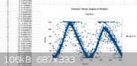
currently processing any of the data so I had to use open office calc (pretty severe lag doing so). Here it is though, 0.03* readings with 250
intensity measures possible! Takes about 9 seconds for a run. Well the initial calibration routine will likely require a minute or so.
Edit - Also I think the second peak is shorter then the first perhaps due to laser misalignment. Thought I had a steady aim when I set it up but cut
me some slack the photoactive surface of the BPW-21 is(eyeballing not from the data-sheet) probably 3mm by 3mm. I can correct by scaling these things
in the soft-ware anyways.
[Edited on 17-5-2014 by smaerd]
Edit - Just realized I'll likely have to do some kind of fourrier transform or sinuisoidal regression to get what I want. Oh the joys of higher math!
[Edited on 18-5-2014 by smaerd]
|
|
|
aga
Forum Drunkard
Posts: 7030
Registered: 25-3-2014
Member Is Offline
|
|
WooHoo !
Congratulations !
A Machine is Born.
Edit: Not may people know, but Excel has a feature that can perform Fourier Transformations, plus much much more..
Granted, not a perfect solution, but useful in the dev process.
[Edited on 18-5-2014 by aga]
|
|
|
smaerd
International Hazard
Posts: 1262
Registered: 23-1-2010
Member Is Offline
Mood: hmm...
|
|
Well I don't want to get ahead of myself just yet hehehe. Yes though, theoretically I could use the instrument as is to receive some amount of
polarimetry measurements. Well not right now but hopefully by tomorrow (read below to see why). I was having serious stability issues with readings
and of course, the noise (I'll be bitching about that a bit until it's reasonable). Then while testing a relay to turn on/off the laser - shit hit the
fan. My readings gradually ended up being a line of noise at around 0 intensity units. Had to disassemble the actual instrument detector(BPW-21) and
solder the connections. Lesson learned... Cutting corners, by wire wrapping + heat shrink, isn't good enough for rotating detectors(... can I get a
face-palm? ...).
On the bright side. Created and tested the new single stage transimpedance op-amp circuit (LTC1050) with the BPW-34 I was hitting nearly 5V with a
high intensity flashlight and 200mV with ambient room lighting(not too shabby!). The awful disgusting sloppy how did it even work single rail LM358N
op-amp was getting about 2.0V with the same light and diode. The LTC1050 is not a single rail but I created a cute little voltage divider mostly for
noise handling(decoupling capacitors etc) anyways. Might, do dual stage depending on linearity and noise (resistive load is 220kOhm for now, 100kOhm
was acceptable as well though). Will be testing the instrument further, working on noise reduction, and the calibration algorithm hopefully tomorrow.
Hoping that the crappy connections on the diode were a contributing factor to the noise and solves the erm, minor issue of not getting data out of the
test routines . Fingers crossed.
Thankfully I wrote a simple harmonic regression algorithm before it totally tanked. No excel unforunately (Linux OS here) but there are a few nice
algorithms in the OpenOffice Calc soft-ware that I use. Thanks for the tip! A Fourier Transform would be wonderful to work on, not that there aren't
royalty free Fast Fourier Transform JAVA algorithms readily available, but it's likely unnecessary. I may write one if I get incredibly bored or if
this thing doesn't function well. Would be nice to explore the concept from another perspective (only dealt with it on paper).
The harmonic regression is my way to reposition/calibrate the polarimeter without a sample in the instrument. So the motor rotates a full period or
(180* on the analyzer) and interpolates the next dark spot. Then it will rotate to just before that darkest region. Such that the motor can reach a
'constant' velocity (ignoring mechanical hysteriasis), hit the known dark point and take readings 360* with a sample present. The soft-ware will then
plot the results and give the desired maxima information. I was developing pretty 'decent' fit's using the regression I developed but, the noise was a
serious issue. Total square error with tons of noise only in the ten thousands for 6288 points (half of a rotation but a full period). Can't remember
if that was before I was square-rooting the values or not. The phase shift seemed to be off by +/-0.0X radians. Didn't get to finish my analysis.
Amplitude seemed suitable, had to do a mean analysis every half degree for comparison. Without the noise that routine could be really fine tuned.
Curve fitting is so useful and so often left out of instrument soft-ware. Although, it's rarely necessary especially for polarimetry measurements. How
many times have I had to create a spread-sheet to use a non-linear equation solver, or make trend-lines to get a piece of information? Dozens...
Having a regression off the bat is useful for interpolating future values/theoretical understandings/seeing trends or behavior. Guess if I need to
develop it for the soft-ware why not include it?
Thanks for following this AGA. It's hard to be so excited about something and have no one to talk with about it. Can't wait to actually use this thing
for the several projects I realllly want to do.
[Edited on 19-5-2014 by smaerd]
[Edited on 19-5-2014 by smaerd]
|
|
|
aga
Forum Drunkard
Posts: 7030
Registered: 25-3-2014
Member Is Offline
|
|
Switching the Laser would be easiest/least noisy using a mosfet.
Things like the IRL2203N go full-on (7 milli-ohm!) with just 4v gate voltage, which you should easily get off the Arduino.
ISTR that it's the 'N' suffix that denotes this on most mosfets.
Supply decoupling is always helpful.
Make sure you have a 1000uF and a 100nf capacitor in parallel across the +ve and -ve supplies to the op-amps & detector.
The motor will probably be throwing junk back into the supply, so try filtering the supply leads using an RF choke or even a ferrite bead, depending
on the frequency of the noise.
You might find that shielding the motor also helps, which is easily done with a bit of tin can with an earth wire soldered onto it.
Back EMF may also be happening.
This can be mitigated by putting a diode the wrong way round (anode to -ve, cathode to +ve) across the connections to the motor, plus another 100nf
capacitor there as well, plus a 10nf capacitor from each motor supply connector down to ground.
Finally there is Impedance Matching between the detector and the op-amp, and between op-amp stages (if there's more than 1 stage).
|
|
|
smaerd
International Hazard
Posts: 1262
Registered: 23-1-2010
Member Is Offline
Mood: hmm...
|
|
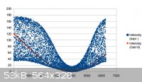
New op amp in place. Definitely interesting results. Looks like there isn't noise, but an AC voltage? Going to try some capacitor filtering on the
transimpedance circuit to see if I can clear this up. However, the data does not look 'stray' it looks like it is oscillating (wildly). Can see my
harmonic regression's predictive result giving a 'decent' fit for the phase shift at least (needs some help though). Here's to hoping all of the noise
from the last circuit was from the crummy op-amp, and that I can clear this up without much effort!
[Edited on 21-5-2014 by smaerd]
[Edited on 21-5-2014 by smaerd]
|
|
|
smaerd
International Hazard
Posts: 1262
Registered: 23-1-2010
Member Is Offline
Mood: hmm...
|
|
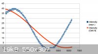
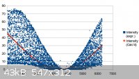
So it begins, the balancing of the filtering capacitor and gain. At least I know my circuit is oscillating now and there is very low noise even
without shielding beyond a piece of tin foil from the motor/PWM!
Pictured below are two quick attempts at feed-back capacitance hunting. O.1uF cap(serious loss of gain) and a 270pF cap(loss of gain and still
oscillating). Wish me luck, something tells me this will be a night-mare without an oscilliscope and a bank of capacitors...
[Edited on 22-5-2014 by smaerd]
|
|
|
aga
Forum Drunkard
Posts: 7030
Registered: 25-3-2014
Member Is Offline
|
|
If it's the op-amp oscillating, it will be due to too much gain, or some loose coupling between the in and out pins.
Are you on a PCB now or still on a breadboard or wire-wrap ?
If you could post the amplifier circuitry, maybe some of us could help.
[Edited on 22-5-2014 by aga]
|
|
|
smaerd
International Hazard
Posts: 1262
Registered: 23-1-2010
Member Is Offline
Mood: hmm...
|
|
I am still on bread board because I am afraid to transfer to PCB as the gain I am getting is too small for what I would like. Debating on a two stage
but that could make the oscillations way worse.
Here is the circuit with the wild oscillations:
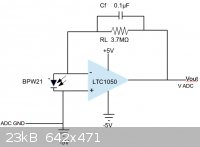
Here is the circuit where the last two results came from(the Cf cap was what was changed):
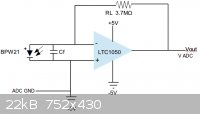
I think in the end I might need a small capacitor in the 100-1000's of pF's parallel with the photodiode, and a larger cap parallel with the feed-back
resistor. So I don't lose too much signal or clip(clipping was observed in the second circuit diagram with the 0.1uF Cf), but am not getting so much
oscillation overloading the bandwidth of the op-amp, but am still smoothing the feed-back resistor noise.
[Edited on 22-5-2014 by smaerd]
|
|
|
aga
Forum Drunkard
Posts: 7030
Registered: 25-3-2014
Member Is Offline
|
|
Both circuits look like madness, however i wil have to do a bit of research to work out the maths.
|
|
|
| Pages:
1
2
3
4
5
6
..
9 |


