| Pages:
1
..
15
16
17
18 |
Dave Angel
Hazard to Others

Posts: 128
Registered: 22-3-2005
Location: UK
Member Is Offline
Mood: 0 K
|
|
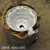
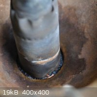
Castner progress this weekend: drilled out the crucible, and fitted the cathode, mesh and collection bell. Schematic below - there is a slight taper
to the cathode due to its origin:
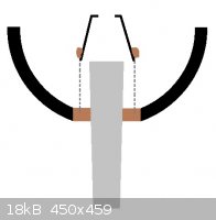
A 100-mesh stainless steel mesh was used in place of the iron fabric. The bell is an upturned SS hip flask cup with a ca. 15 mm hole drilled in the
bottom. Mesh and bell fixed together with fire cement.
The cathode was positioned through a 44mm hole drilled in base and cemented in place with more fire cement. The mesh-bell assembly was embedded into
the cement, over the cathode, and a fire lit in the bowl to set the cement.
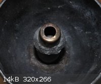
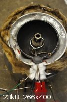
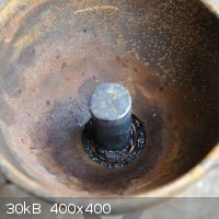
Unfortunately, during the firing, the cathode slipped to an angle (see picture, below) so it is no longer central. I'm somewhat tempted to break the
whole assembly out and reset it, maybe using a high temperature epoxy rather than awkward fire cement.

Does anyone knows if a functional cell will not be possible with the uneven voltage division and current densities resulting? If it's just a case of
reduced efficiency then, since this is just a trial build, I'm probably going to push ahead with it regardless. The main goal is a β-alumina
cell, though I may build a more robust Castner in time to determine the optimal parameters.
|
|
|
BromicAcid
International Hazard
Posts: 3227
Registered: 13-7-2003
Location: Wisconsin
Member Is Offline
Mood: Rock n' Roll
|
|
Just a comment, I once set an electrode for a Castner cell using high temp epoxy. The small scale cell showed some pitting, once I moved it up to
full scale the epoxy dissolved in about 20 minutes, thankfully it was vigorous enough that I noticed it bubbling even with the current off. Take
care.
|
|
|
Dave Angel
Hazard to Others
Posts: 128
Registered: 22-3-2005
Location: UK
Member Is Offline
Mood: 0 K
|
|
Thanks for the heads up Bromic; on that back of it, I've decided to properly test the resistance of the fire cement to molten alkali.
I took a small piece of wet cement, fired it with a blow-torch (probably too fast), broke it up and immersed a chunk in molten NaOH at ca. 400 °C.
This fizzed for a short while with evidence of the black cement disintegrating at first, but then this subsided and I saw no evidence of breakdown. I
wonder if residual water and/or surface silica/silicate on the cement was reacting, leaving a mass of the more resistant resin and fillers.
The results give me a little more confidence that a properly fired cement should be able to resist the conditions, at least long enough to produce
enough sodium for an alumina cell. As a result, (and because I can't stand looking at the crooked electrode) I've decided to break it out and I'll
soon be rebuilding the cell with a steadily ramped firing.
|
|
|
Dave Angel
Hazard to Others
Posts: 128
Registered: 22-3-2005
Location: UK
Member Is Offline
Mood: 0 K
|
|
Poor-man's spot welder success!
Having searched the forum I see that the MOT spot welder is old news, but as a quick aside I just this week came across the hack-a-day when looking for a better way to make the stainless steel mesh cylinder and affix it to the collection bell.
Most of my Sunday consisted of building and using this:
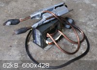
Of anything I've built, it wins the prize for use of the oldest hoarded bits; the transformer having been salvaged 11 years ago, tungsten electrodes
bought about 8 years ago and a stapler I've had since 'high school'! It ain't pretty but cost less than £10 for the 8 AWG cable. Bonus points for
excessive use of duct tape 
Anyway, my welds aren't pretty; I had to judge the pressure by hand and time the weld by switching the power at the socket, but... it's my first foray
into welding and it's done the job:
This is so much neater than my original attempt with fire cement, and leaves the embedding of the structure in the base of the pot as the only place
where the cement is really required to hold up. Slowly getting there!
|
|
|
m1tanker78
National Hazard
Posts: 685
Registered: 5-1-2011
Member Is Offline
Mood: No Mood
|
|
Nice call with the MOT spot welder! I have several of them around the shop and in fact, I learned to stick weld with the first MOT I modified. Still
have that welder and turn to it every now and then because it's built like a little tank.
I look forward to seeing your progress with the Castner cell you're building. I've been running a crude Downs cell (NaCl electrolyte) on and off for a
while now but the sodium must still be scooped out. I'm brainstorming ideas to construct a cell that would practically be set it and forget it -
sodium on tap! Easier said than done but NOT impossible.
Good luck,
Tank
Chemical CURIOSITY KILLED THE CATalyst.
|
|
|
Dave Angel
Hazard to Others
Posts: 128
Registered: 22-3-2005
Location: UK
Member Is Offline
Mood: 0 K
|
|
Thanks for the words of encouragement Tank! This is one of the more involved projects I've taken on and there are many hurdles to
overcome. It would be great to see your Downs cell - have you posted it before? I couldn't find it with a cursory search.
Thoughts of automation have also crossed my mind - some sort of pump (Viton peristaltic, connected to micro bore copper tube?) and a simple sodium
level sensor, e.g., copper wire at various heights connected to an appropriate circuit to detect when enough has built up to pump, and when to stop
it. Fresh salt could be introduced using a powder moving screw type arrangement... Still, this is far into the future for me - just getting my 'Sodium
Badge' will be a great personal achievement...
For now
Progress this bank holiday weekend:
Fixed the cathode and SS mesh / collection bell combo in place
Formed an anode option
Experimented with heating element options
Built the power supply
Cathode etc. installation:
Fire cement used here - the only real weak point where the molten alkali could spell the end for my cell. Having previously fired it using a
combination of a hot oven, blow-torches and plain old wood fire, I've elected to use a more controlled process this time.
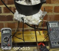
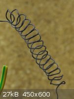
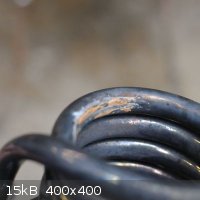
A U-tube of 8 mm diameter 0.6mm wall copper tube was formed and a tightly wound coil of NiChrome wire fed through, wrapped with a spiral of glass
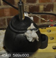
fibre weave for electrical isolation. You can see the firing set-up for setting the mesh in place below - voltage, temp and current (just off shot)
being monitored on separate meters. The second shot shows the cathode firing set up, and the now heavily oxidised copper U-tube more clearly. Voltage
is controlled accurately by an 8 A variable transformer (off-camera), but could just as easily be controlled by the circuit from linearly variable
heat gun on a budget. Ceramic wool is used to thermally insulate the set-up.
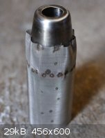
Anode construction:
About 5 attempts have been made at this and left me with a fair bit of scrap copper. This is the best result:
 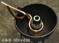
Using the same 8 mm copper tubing as above, a section was filled with free-running table salt and the ends hammered shut, allowing bending to be free
of major kinks. The tube was bent around the same 1 3/4 inch (44 mm) hole cutting bit used to drill the hole in the bottom of the mortar, as it is,
conveniently, a good size to give the correct spacing ratio of the cell electrodes from the mesh. I will get this plated with about 500 microns of
nickel.
Now, I know what you're thinking, 'why not run the heating coil for the cell through the anode like for the cement firing?' This is the preferred
option, though there are a couple of issues to deal with:
1) How to insulate the nichrome from the copper?
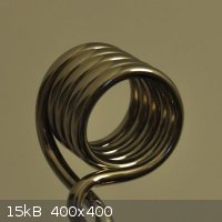
I've already used glass fibre weave successfully, though it only exacerbates the second issue (see below). So to provide a non-bulky electrically
insulating layer over the nichrome I've done a little proof of concept work:
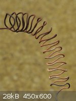  
Nichrome was salvaged from an old electric heater - thanks to len1 for pointing out this, in my hindsight obvious, source - and for
the rest of the Castner learnings frankly! The wire was wound into a short spiral and plated in a bath as described by Cyrus here, though without the thiourea (as I don't have any). The fine layer of copper was oxidised in place by passing current. The layer was tested
and found to be electrically insulating.
2) How to feed the heating coil through the anode?
This is a bit trickier. I've tried feeding the heating coil directly into the anode, using different gauges of copper wire to lead it. Also tried
string, cotton thread, brass wire, and using a magnet, and vacuum in an attempt to draw these through (with appropriate attachements to the end of the
lead-cord).
None of these techniques seem to get it very far - it always gets caught somewhere. I'm thinking that the magnet technique to guide a light-weight
thread round will probably still be the best bet, but does anyone have any better ideas?
Fall-back heating option:
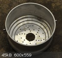 
Not a lot to report here. I found, and put a 44 mm hole in the bottom of, an old aluminium steamer. At the least, this will provide a container for
the insulating material, and should I not be able to fit the anode with a heating coil, it will form a custom heating mantle for the cell.
Power Supply:
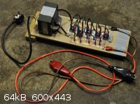
Thanks again to len1 for the power supply design he described earlier in the thread. I've built something similar using the MOT from
the quick and dirty spot welder with 5 turns of 8 AWG cable and 5 x 25 A bridge rectifiers in parallel - some more 8 mm copper tube was hammered flat
and drilled to provide cheap bus bars for this purpose. It puts out almost exactly 5 V. Since taking the photo I've added some proper feet to give the
bolts protruding on the bottom some stand-off.
I did try a build with a computer PSU but found this to be unreliable. With suitable cooling (maybe even a case to keep bare wires contained for a
change!) the PSU above should be far more robust.
Well, that's all for now, will be getting the anode plated in the next couple of weeks and exploring the heating options as the next priority.
Comments and advice, naturally, welcome!
|
|
|
m1tanker78
National Hazard
Posts: 685
Registered: 5-1-2011
Member Is Offline
Mood: No Mood
|
|
Quote: Originally posted by Dave Angel  | Thanks for the words of encouragement Tank! This is one of the more involved projects I've taken on and there are many hurdles to
overcome. It would be great to see your Downs cell - have you posted it before? I couldn't find it with a cursory search.
|
I started a thread but as I recall, it turned into a pissing contest due to my sloppyness. I made some modifications and improvements to the cell but
ultimately stuck with the KIS,S approach. I've since performed a ton of experiments with different salts, anodes, cathodes, methods of collecting
sodium, etc..
To be honest, if I need some sodium I just fire up the power supply and "roast some marshmallows" (my neighbor's words). I sit there with a long scoop
and when enough sodium forms on the melt, I scoop and dump then refine. 
I'll look through my old pics and post some images of my makeshift Downs cell projects when time permits. I salute you for being a better planner and
thinking your design through (unlike me) heh.
Tank
Chemical CURIOSITY KILLED THE CATalyst.
|
|
|
Dave Angel
Hazard to Others
Posts: 128
Registered: 22-3-2005
Location: UK
Member Is Offline
Mood: 0 K
|
|
I find it disappointing when this happens - as amateurs, it is worth encouraging each other in the simpler / inventive / resourceful approaches,
particularly as our resources become restricted by endless wars on terror/drugs/'chemicals'.
Heh, 'roasting marshmallows' brings really vivid images to mind... I'd not likely be the only one to find interesting your successful blends of salts
for your Downs cell, not to mention configuration and materials - I'll look forward it when you get the chance.
Finally, I've got a quick update - a shiny anode back from the platers today. Like the cathode, ca. 500 microns of nickel on this:
I'm still slightly in awe of what electroplating does, no matter how commonplace it may be.
I'll take a leaf out of Tank's 'KIS,S' book and stick with external heating for this first cell, saving the heated anode idea for a
future build once I've ironed out the basics.
|
|
|
Dave Angel
Hazard to Others
Posts: 128
Registered: 22-3-2005
Location: UK
Member Is Offline
Mood: 0 K
|
|
Success!
I'm pleased to report that I've made sodium with my Castner cell
Summary of recent work:
I built some feet into the base of the old steamer with threaded rod and nuts, wrapped it in loft insulation and lined the inside with a crucible
form-matching packing of ceramic wool. A coil of fresh, 22 SWG nichrome was pressed into the wool to provide the initial heating.
The crucible itself had the anode coil fitted using fire cement and an additional, ca. 15 mm, 'puck' of cement was also added to the base for extra
containment should the base dissolve through. A sheet of twill weave fibreglass mat was placed over the nichrome coil and the crucible lowered into
place. Temperature probes were inserted in two places: solid probe at the crucible wall and flexible probe through the anode for a core measurement.
The set up took about 1.5 Kg of molten alkali (OTC drain cleaner variety) to bring it to a working capacity, and probably took about 45 minutes to
come to temperature (max. 330 °C) - I cannot report accurate figures as I was more concerned with safety and successful operation than time keeping.
I had an exciting moment with sodium catching fire (argon blanket then installed), and I was on the clock given the effects the molten alkali was
having on the cement...
Length of operation estimated at 2.5 hours given the timestamps on photos. Current is unknown as the actively cooling case I built around my PSU
prevents access to the appropriate wires; a built-in ammeter for the next upgrade, I think. On the topic, the cooling was achieved by encasing the PSU
in a long rectangular wooden box, open at both ends, with a microwave fan wired in at one end - very simple and effective.
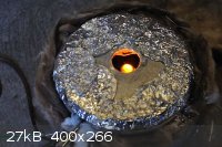
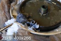
Results:
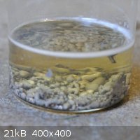 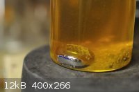
Sodium was collected with disposable pasteur pipettes, which worked about half the time; the other half of the time, the sodium froze in the glass.
The first photo is the metal I managed to pipette out, prior to purification. The second photo was taken during purification of the material which
froze in the pipettes, these having been crushed and heated under oil.
Findings and learnings:
I still don't like sodium hydroxide, particularly not molten and especially not at these volumes. I can echo the sentiments and findings of others; it
fumes and spits, gets everwhere, and is generally unpleasant to work with. I'd previously oven baked about 1 Kg of hydroxide to remove any water, but
had to add another 0.5 Kg, un-dried, to fill the cell. Some significant foaming during the first 15 minutes of operation could probably have been
avoided had the entire quantity of salt been thoroughly dried.
My cell was not insulated well enough / delivering enough current to maintain temperature without external heating. Unfortunately the nichrome broke
about half-way through the run; a stray piece of hydroxide lost during filling having acted on it I suspect. Still, the cell carried on whilst very
slowly losing heat, and actually seemed to become more 'sedate' (if one can apply that word to such an experiment) at lower temperatures, i.e., just
above melting point.
Coalescence of the liquid sodium during purification under oil was far easier with the broken glass present, and I observed that lumps of alkali
impurities appeared to help more so. Perhaps a simple physical effect of helping to break the surface tension - could be replicated with unglazed
ceramic maybe?
Next steps:
Yield:
For this I intend to coalesce the entirety of the metal into one ingot under a suitable solvent; I have mixed xylenes on hand, with b.p. 140 °C, so
figure this could work under reflux, providing the beads will come together.
Disassembly:
I've washed the cell out and it's going to come apart so I can fully assess the damage from the operating conditions.
Downs cell:
I intend to trial this option using my, now empty, argon canister as a crucible. I likely have enough sodium to build a β-alumina cell but would
be more comfortable with an additional batch, and I'd like to have personal experience with all three methods to make a fair comparison.
Further update soon to follow...
[Edited on 23/9/2012 by Dave Angel]
|
|
|
BromicAcid
International Hazard
Posts: 3227
Registered: 13-7-2003
Location: Wisconsin
Member Is Offline
Mood: Rock n' Roll
|
|
Love it Dave! My full scale Downs cell was a veritable disaster, glad to see it work out to some extent for another. Looking forward to your future
updates.
|
|
|
cal
Hazard to Self
Posts: 88
Registered: 7-2-2012
Member Is Offline
Mood: No Mood
|
|
SODIUM CELL
This is from Synthesis of Laboratory Reagents by LEONID LERNER
Setup and Operation
A 500–1000-mL nickel crucible with 10–12 cm top diameter is filled with 800–1000
g 99% commercial NaOH, placed inside a crucible oven, and heated to a temperature
of 360°C–380°C, as indicated by a thermocouple placed inside the melt. It is best to
protect the thermocouple by a close-fitting copper sheath, which can be made of a
sealed section of 3/16-in. copper tubing. This is best located in the anode compartment
directly behind the nickel separator where the temperature registered is not prone to
spurious variation due to intermittent contact with molten sodium. The NaOH takes
about 2 h to melt fully, whereupon 40 g of dehydrated Na2CO3 is added (this serves to
reduce the sodium diffusion rate, α , and the melt is held for an additional
½–1 h at , and the melt is held for an additional
½–1 h at
that temperature to almost complete dehydration. Thereupon, the oven is turned off
and a nickel separator, about 7 cm in diameter lowered to extend about 1–2 cm below
the melt surface. When the electrolyte has cooled to 318°C, an overhead cathode, at
a voltage of 12–15 V with respect to the nickel crucible anode, is lowered so that its
tip just touches the electrolyte, and current begins to flow. The high voltage produces instantaneous heating, preventing immediate formation of an
insulating crust on the
electrode.
As soon as the current exceeds 20 A, the voltage is wound back to an average
operating level of 6.3 V at 318°C. There upon the cell voltage is computer-controlled
to counteract thermal runaway. This is achieved by decreasing the cell voltage linearly
as a function of temperature, so that at 316°C the cell voltage rises to 6.7 V,
with a corresponding decrease for a temperature variation in the other direction.
This control does not need to be precise timewise, and a digital output fed through
a low-pass filter with a 10-sec. time constant has proved adequate. During this time
the cell current should vary in the range 25–55 A.
After a period of 10–15 min, more sodium starts dissolving than is reacting with
the diffusing water, and hydrogen evolution moves outside the cathode compartment.
This is accompanied by a sudden surge in current above 60 A, which is used to trigger
an alarm indicating sodium needs to be removed from the cell. The cathode is
lifted out, and a strainer (mesh 30/32 is adequate) is used to lift the pool of sodium
and empty it into a container of paraffin. This method is used in the original Castner
patent, and works because sodium has a reasonably high surface tension compared
to the electrolyte. Any electrolyte frozen on the surface of sodium globules can be fitted with a 1–2-cm steel cylinder on which the mesh rests. In
this case, any residual
NaOH in the strainer freezes to the walls of the cylinder when the sodium is poured.
Although a small amount of sodium is lost this way, the recovered sodium is clean
and ready for use (Figure€2.6).
The sodium should be removed from the cell as quickly as possible (the whole
operation should take no more than about 30 sec, so that the melt surface does not
have time to freeze), and the cathode tips are cleaned off any adhering solidified
electrolyte by pressing between the jaws of small pliers so that the solidified melt
flakes off. The cathode can now be reinserted, touching it against the electrolyte to
commence the flow of current. When a globule of sodium has formed after about 30
sec or so, the cathode is raised 1–2 mm, and the whole process repeated. It should not
now be necessary to raise the voltage above the normal level on reinsertion because
the cathode is still hot. To prevent excessive freezing of the electrolyte surface during
sodium removal, which can lead to spitting and small explosions upon recommencement
of electrolysis, the oven is set to turn on when the bath temperature dips below 314°C, which occurs only for a few minutes following sodium removal.
After 80–100
g of sodium has been collected, fresh sodium hydroxide needs to be added (sodium
carbonate is not added as it is not electrolyzed).
Although it is often suggested that prior to use sodium be cleaned from the
adhering oxide/hydroxide crust by remelting and rolling under xylene [1], the evaporation
rate of xylene above the mp of sodium has been found to be too high, and
xylene is not very effective in removing the oxide crust. On the other hand, the bp
of xylene is still high enough to present some removal problems, and it is unsuitable
for long-term sodium storage because sodium rapidly oxidizes under it. In this
respect, paraffin oil is superior. Not only does sodium retain its luster for months
when stored under paraffin, but by heating the paraffin to above 120°C a light
crust cover disappears in a matter of minutes, due to saponification of the paraffin
and dissolution. To remove thicker crusts, the sodium surface can be trawled with
fine stainless steel mesh. The paraffin adhering to the sodium surface cannot be
volatilized as it has a very high boiling point, and some of its constituents carbonize
without vaporizing even under a vacuum of 10−3 torr. However, paraffin can be
fairly effectively removed by wiping the sodium with an absorbent lint free cloth,
which still leaves a very thin layer of paraffin adhering to the sodium surface,
preventing rapid oxidation in air during the wiping. The sodium is then shaken
for several minutes with a large quantity of dry ether, which removes the last thin
paraffin coat.
References
1. Furniss, B. S., Hannaford, A. J., Smith, P. W. G., and Tatchell, A. R., Vogel’s Textbook of
Practical Organic Chemistry, 5th ed. London: Addison Wesley Longman, 1989.
2. Birch, A. J., Reduction by dissolving metals. Part I. J. Chem. Soc. 117: 430–436, 1944.
3. Moody, C. J. ed., Synthesis: Carbon with two attached heteroatoms with at least one carbon-
to-heteroatom multiple link, pp. 27–8. Vol. 5 of Comprehensive Organic Functional
Group Transformations, edited by Katritzky, A. R., Moody, C. J., Meth-Cohn, O., and
Rees, C. W. New York: Pergamon, 1995.
4. Mordini, A., Sodium and potassium. In Main Group Metal Organometallics in Organic
Synthesis, edited by McKillop, A. New York: Pergamon 2002; Jenkins, J. W., Nalo, L.
L., Guenther, P. R., and Post, H. W., Studies in silico-organic compounds. VII. The
preparation and properties of certain substituted silanes. J. Org. Chem. 13(6): 862–866,
1948; see also Chapter 10.
5. Davy, H., On some new phenomena of chemical changes produced by electricity, Phil.
Trans. Roy. Soc. 98: 1–44, 1808.
6. Castner, H. Y., Process of Manufacturing Sodium and Potassium. U.S. Patent No.
452030, May 12, 1891.
7. Wallace, T., The Castner sodium process, Chem. Ind. 876–882, 1953.
8. Lorenz, R. and Clark, W., Über die Darstellung von Kalium aus Geschmolzenem Ätzkali,
Zeit. Elektrochem. 9: 269–71, 1903.
9. Allmand, A. J. and Ellingham, H. J. T., Principles of Applied Electrochemistry, 2nd ed.,
pp. 498–502. London: Edward Arnold & Co., 1924.
10. Thomson, G. W. and Garelis, E., Sodium: Its Manufacture, Properties, and Uses,
pp.€20–23. New York: Reinhold Pub. Corp., 1956.
© 2011
|
|
|
cal
Hazard to Self
Posts: 88
Registered: 7-2-2012
Member Is Offline
Mood: No Mood
|
|
SODIUM CELL
This is from Synthesis of Laboratory Reagents by LEONID LERNER
Setup and Operation
A 500–1000-mL nickel crucible with 10–12 cm top diameter is filled with 800–1000
g 99% commercial NaOH, placed inside a crucible oven, and heated to a temperature
of 360°C–380°C, as indicated by a thermocouple placed inside the melt. It is best to
protect the thermocouple by a close-fitting copper sheath, which can be made of a
sealed section of 3/16-in. copper tubing. This is best located in the anode compartment
directly behind the nickel separator where the temperature registered is not prone to
spurious variation due to intermittent contact with molten sodium. The NaOH takes
about 2 h to melt fully, whereupon 40 g of dehydrated Na2CO3 is added (this serves to
reduce the sodium diffusion rate, α, and the melt is held for an additional
½–1 h at
that temperature to almost complete dehydration. Thereupon, the oven is turned off
and a nickel separator, about 7 cm in diameter lowered to extend about 1–2 cm below
the melt surface. When the electrolyte has cooled to 318°C, an overhead cathode, at
a voltage of 12–15 V with respect to the nickel crucible anode, is lowered so that its
tip just touches the electrolyte, and current begins to flow. The high voltage produces instantaneous heating, preventing immediate formation of an
insulating crust on the
electrode.
As soon as the current exceeds 20 A, the voltage is wound back to an average
operating level of 6.3 V at 318°C. There upon the cell voltage is computer-controlled
to counteract thermal runaway. This is achieved by decreasing the cell voltage linearly
as a function of temperature, so that at 316°C the cell voltage rises to 6.7 V,
with a corresponding decrease for a temperature variation in the other direction.
This control does not need to be precise timewise, and a digital output fed through
a low-pass filter with a 10-sec. time constant has proved adequate. During this time
the cell current should vary in the range 25–55 A.
After a period of 10–15 min, more sodium starts dissolving than is reacting with
the diffusing water, and hydrogen evolution moves outside the cathode compartment.
This is accompanied by a sudden surge in current above 60 A, which is used to trigger
an alarm indicating sodium needs to be removed from the cell. The cathode is
lifted out, and a strainer (mesh 30/32 is adequate) is used to lift the pool of sodium
and empty it into a container of paraffin. This method is used in the original Castner
patent, and works because sodium has a reasonably high surface tension compared
to the electrolyte. Any electrolyte frozen on the surface of sodium globules can be fitted with a 1–2-cm steel cylinder on which the mesh rests. In
this case, any residual
NaOH in the strainer freezes to the walls of the cylinder when the sodium is poured.
Although a small amount of sodium is lost this way, the recovered sodium is clean
and ready for use (Figure€2.6).
The sodium should be removed from the cell as quickly as possible (the whole
operation should take no more than about 30 sec, so that the melt surface does not
have time to freeze), and the cathode tips are cleaned off any adhering solidified
electrolyte by pressing between the jaws of small pliers so that the solidified melt
flakes off. The cathode can now be reinserted, touching it against the electrolyte to
commence the flow of current. When a globule of sodium has formed after about 30
sec or so, the cathode is raised 1–2 mm, and the whole process repeated. It should not
now be necessary to raise the voltage above the normal level on reinsertion because
the cathode is still hot. To prevent excessive freezing of the electrolyte surface during
sodium removal, which can lead to spitting and small explosions upon recommencement
of electrolysis, the oven is set to turn on when the bath temperature dips below 314°C, which occurs only for a few minutes following sodium removal.
After 80–100
g of sodium has been collected, fresh sodium hydroxide needs to be added (sodium
carbonate is not added as it is not electrolyzed).
Although it is often suggested that prior to use sodium be cleaned from the
adhering oxide/hydroxide crust by remelting and rolling under xylene [1], the evaporation
rate of xylene above the mp of sodium has been found to be too high, and
xylene is not very effective in removing the oxide crust. On the other hand, the bp
of xylene is still high enough to present some removal problems, and it is unsuitable
for long-term sodium storage because sodium rapidly oxidizes under it. In this
respect, paraffin oil is superior. Not only does sodium retain its luster for months
when stored under paraffin, but by heating the paraffin to above 120°C a light
crust cover disappears in a matter of minutes, due to saponification of the paraffin
and dissolution. To remove thicker crusts, the sodium surface can be trawled with
fine stainless steel mesh. The paraffin adhering to the sodium surface cannot be
volatilized as it has a very high boiling point, and some of its constituents carbonize
without vaporizing even under a vacuum of 10−3 torr. However, paraffin can be
fairly effectively removed by wiping the sodium with an absorbent lint free cloth,
which still leaves a very thin layer of paraffin adhering to the sodium surface,
preventing rapid oxidation in air during the wiping. The sodium is then shaken
for several minutes with a large quantity of dry ether, which removes the last thin
paraffin coat.
References
1. Furniss, B. S., Hannaford, A. J., Smith, P. W. G., and Tatchell, A. R., Vogel’s Textbook of
Practical Organic Chemistry, 5th ed. London: Addison Wesley Longman, 1989.
2. Birch, A. J., Reduction by dissolving metals. Part I. J. Chem. Soc. 117: 430–436, 1944.
3. Moody, C. J. ed., Synthesis: Carbon with two attached heteroatoms with at least one carbon-
to-heteroatom multiple link, pp. 27–8. Vol. 5 of Comprehensive Organic Functional
Group Transformations, edited by Katritzky, A. R., Moody, C. J., Meth-Cohn, O., and
Rees, C. W. New York: Pergamon, 1995.
4. Mordini, A., Sodium and potassium. In Main Group Metal Organometallics in Organic
Synthesis, edited by McKillop, A. New York: Pergamon 2002; Jenkins, J. W., Nalo, L.
L., Guenther, P. R., and Post, H. W., Studies in silico-organic compounds. VII. The
preparation and properties of certain substituted silanes. J. Org. Chem. 13(6): 862–866,
1948; see also Chapter 10.
5. Davy, H., On some new phenomena of chemical changes produced by electricity, Phil.
Trans. Roy. Soc. 98: 1–44, 1808.
6. Castner, H. Y., Process of Manufacturing Sodium and Potassium. U.S. Patent No.
452030, May 12, 1891.
7. Wallace, T., The Castner sodium process, Chem. Ind. 876–882, 1953.
8. Lorenz, R. and Clark, W., Über die Darstellung von Kalium aus Geschmolzenem Ätzkali,
Zeit. Elektrochem. 9: 269–71, 1903.
9. Allmand, A. J. and Ellingham, H. J. T., Principles of Applied Electrochemistry, 2nd ed.,
pp. 498–502. London: Edward Arnold & Co., 1924.
10. Thomson, G. W. and Garelis, E., Sodium: Its Manufacture, Properties, and Uses,
pp.€20–23. New York: Reinhold Pub. Corp., 1956.
© 2011
|
|
|
Dave Angel
Hazard to Others
Posts: 128
Registered: 22-3-2005
Location: UK
Member Is Offline
Mood: 0 K
|
|
| Quote: Originally posted by BromicAcid | | Love it Dave! My full scale Downs cell was a veritable disaster, glad to see it work out to some extent for another. Looking forward to your future
updates. |
Thanks, Bromic! This one has been on my to do list for so long and it feels great to have finally cracked it, particularly since Davy
was isolating his sodium, oh, nearly 200 years ago...
Based on cal's post, I've elected not to use xylene for purification:
| Quote: |
Although it is often suggested that prior to use sodium be cleaned from the adhering oxide/hydroxide crust by remelting and rolling under xylene [1],
the evaporation rate of xylene above the mp of sodium has been found to be too high, and xylene is not very effective in removing the oxide crust. On
the other hand, the bp of xylene is still high enough to present some removal problems, and it is unsuitable for long-term sodium storage because
sodium rapidly oxidizes under it. In this respect, paraffin oil is superior. |
So instead, I've today invested in some baby oil (Johnson's). This contains mineral oil for the most part, and some isopropyl palmitate and fragrance,
though likely not much given how stingy such companies are with their ingredients. Anyway, this will suffice until I can get some pure mineral oil.
I had been using '3-in-1' brand oil for purification, but this seems to lose its lighter fractions and thickens up considerably, plus I'm not sure
what sort of additives might be in it. Additionally, I stored the sodium under kerosene (Bartoline brand 'paraffin', from B&Q) overnight and
observed a layer of red powder over the exposed material this morning, so clearly something is reacting - again, unsuitable.
Coalesence and purification complete:
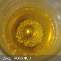 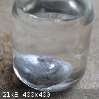
The ingot weighs ca. 14 g (I don't trust the decimal point on my balance - it's time for a new one) so I'm quite pleased with that for a first
attempt. I actually found (obvious in hindsight) that the coalescence works best as the sodium is solidifying; holding the beads at melting point and
then cooling whilst gently stirring brings it all together nicely. Its behaviour reminds me of solder...
I've also partly dismantled the cell. The anode coil came away from its fixing as soon as the cell was washed out, and it's evident that it was in
contact with the gauze at some point - I imagine towards the end of the run, when there seemed to be something amiss, with some popping / small
explosions. This, along with the temperature drop, is what ultimately led me to end the run. Additionally, the alkali has managed to (as feared) eat
quite heavily into the fire cement at the base - it did not take much to remove the gauze, so it looks like 2 - 3 hours is about as much as one can
get out of a reasonable quantity of the cement used (KOS brand, black). Also, the plating on the cathode seems to have been breached, as evidenced by
the rusty marks on the tip, but I have not yet attempted to clean this up to see if it's just iron oxide that's been splashed on the top, or actually
from the cathode itself - the plater did warn me that the coat would be thinner there.
With some refitting using the learnings above, this cell could be made sturdier and deliver a significant run. However, given the unpleasant
experience that is working with molten alkali, I'm shelving this design for now. Looking at the Downs cell, the first thing that comes to mind is the
need for a PSU rewind for higher voltage; 7 to 8 V for an effective process vs. my 5 V used for Castner... Already started working on the cell's
melting pot but that's a post for another day
[Edited on 23/9/2012 by Dave Angel]
|
|
|
Magpie
lab constructor
Posts: 5939
Registered: 1-11-2003
Location: USA
Member Is Offline
Mood: Chemistry: the subtle science.
|
|
Nice work Dave. Your vision and persistence have paid off. You have a workable design that enables the production of a significant quantity of
sodium - a claim that not many can make although many have tried.
Your solution to a truly robust design is now the proper selection of materials of construction. And perhaps you feel that some tweaking of the
design is needed to improve safety and control.
I look forward to seeing your Down's cell.
The single most important condition for a successful synthesis is good mixing - Nicodem
|
|
|
m1tanker78
National Hazard
Posts: 685
Registered: 5-1-2011
Member Is Offline
Mood: No Mood
|
|
The shiny ball of sodium metal speaks volumes to the time and effort you invested in your cell. You ran into some problems but you gained experience
and you now have a landmark, if you will, for future designs and material selection.
Nice work Dave!
http://www.sciencemadness.org/talk/viewthread.php?tid=16225
^This thread is an idea dump for cleaning up sodium and potassium and sort of outlines my, umm, adventures with reclaiming and cleaning sodium scraps.
You mentioned that broken glass helped the smaller sodium beads to coalesce..
Tank
[Edited on 9-24-2012 by m1tanker78]
Chemical CURIOSITY KILLED THE CATalyst.
|
|
|
Dave Angel
Hazard to Others
Posts: 128
Registered: 22-3-2005
Location: UK
Member Is Offline
Mood: 0 K
|
|
Thanks both - your encouragement means a lot. 'Shoulders of giants' and all that though eh?
| Quote: Originally posted by Magpie | | Your solution to a truly robust design is now the proper selection of materials of construction. And perhaps you feel that some tweaking of the
design is needed to improve safety and control. |
I'd say that refinements on the design would be sealing at the base - could be the use of fused NaCl that I originally proposed, though this would
mean some serious heat. Also, I'd firmly clamp the anode separately rather than trying to cement it in place, then no risk of it moving. Argon blanket
from the beginning might be a good idea and a heated pipette for extraction. Finally, I'd use thicker nichrome (though I've got a roll of 22 SWG to
use before I buy more) to give a more robust heating element. And not get NaOH on it!
Heh, is that a hint to go add to that thread?
To be honest, I'm not sure if the broken glass is what was doing it. I tried prodding and scratching with a piece of broken ceramic insulating
material from the old electric heater and it did nothing. Same with a broken pipette.
When I next make sodium I'll be prepared with some more experiments, but frankly I found that forcing them together (vortex, pliers, pokey-stick etc.)
as they approach freezing point is the simplest way to get the beads to coalesce. Perhaps it was cooling at just the time I observed the glass
interacting with it, and I drew to hasty a conclusion. I'll blame the late hour and the cold!
|
|
|
m1tanker78
National Hazard
Posts: 685
Registered: 5-1-2011
Member Is Offline
Mood: No Mood
|
|
Dave, I found some pics of my early experiments after I abandoned NaOH and switched to NaCl. I blacked out the surroundings to mitigate distractions.
This was my first 'improvement' after much experimenting with different salt mixtures all in an open crucible. Indeed, sodium collected in the
tube but presented considerable difficulty to remove. I could tell when the tube was filled to capacity when I'd see 'fireflies' on the melt. The only
way to collect the sodium was to shut down the power supply and wait until it all cooled to ~ RT. The block was broken and sodium scooped out of the
tube. Assuming all went as planned, yields were usually between 15g and 23g. BTW, what you see here is the pre-heat cycle to get everything up to temp
(beyond, actually).

This is simply a slightly scaled-up version of the above design. Same difficulties too! I ran into some problems with the larger parts sinking too
much heat away but got around that by pouring more salt on top of the melt once everything was positioned. This served to insulate and exclude air
from the melt. The anode is the hottest part of the cell so it never really 'seals' - good thing too! This is the cell during normal operation...

As you can see, it's all very parts bin-friendly. At the time of these pics I was using a DC welder for electrons. I'm now the proud owner of a beefy
programmable TCR power supply.
Tank
Chemical CURIOSITY KILLED THE CATalyst.
|
|
|
Dave Angel
Hazard to Others
Posts: 128
Registered: 22-3-2005
Location: UK
Member Is Offline
Mood: 0 K
|
|
Hey Tank, I like the parts bin use, have enjoyed playing 'spot the part' with your set up - it looks like a case from a D-cell
battery on the top of the tube in the first picture, though I'm not sure as the Dr Pepper can in the second would put the D-cell at a larger scale
than it should be, unless perspective is playing tricks on me...
I'm actually using a galvanised steel bucket for my cell insulation container. It looks like you're not using any external heating before or
during electrolysis - is it melted and kept that way simply by the anode-cathode current? Anyway, I'm rapidly running out of money for builds at the
moment due to my habits of buying specific parts, but hope to make some steady progress over the next couple of months.
By the way, it's an absolute travesty: I've identified that pretty much any molten salt physical data report is available from the NIST website (via
Google) except those volumes reporting on single salts and on binary mixtures of fluorides and those of chlorides! Would be nice to have the
whole collection, and the data most relevant to home chemists - molten chloride mix conductivities would help plan the cell voltage and electrode
spacing etc.
Maybe it's a conspiracy against us 
|
|
|
m1tanker78
National Hazard
Posts: 685
Registered: 5-1-2011
Member Is Offline
Mood: No Mood
|
|
Correct!
| Quote: Originally posted by Dave Angel | | though I'm not sure as the Dr Pepper can in the second would put the D-cell at a larger scale than it should be, unless perspective is playing
tricks on me... |
The cell with the Dr. Pepper can is a scaled-up version of the earlier one with a 'D' cell battery case.
| Quote: Originally posted by Dave Angel | | It looks like you're not using any external heating before or during electrolysis - is it melted and kept that way simply by the anode-cathode
current? |
Also correct.
True. Plan to pump ~35V through your cell in order to reach and maintain the ideal temperature. I had no problems adjusting the current on
the fly with my cheapo inverter welder. The headaches came on when the welder put itself into low power mode due to overheating.
I never got around to trying any fluoride salts in my cells. Chlorine is bad enough! Using calcium chloride has always caused me problems so I stay
away from the stuff.
I'll be looking for my notes so I can give more specific info - wherever possible.
Tank
Chemical CURIOSITY KILLED THE CATalyst.
|
|
|
Dave Angel
Hazard to Others
Posts: 128
Registered: 22-3-2005
Location: UK
Member Is Offline
Mood: 0 K
|
|
| Quote: Originally posted by m1tanker78 | | I never got around to trying any fluoride salts in my cells. Chlorine is bad enough! Using calcium chloride has always caused me problems so I stay
away from the stuff. |
Ah, just to clarify, I don't wish to run with molten fluorides either, I only bring them up for completeness; i.e., the lack of that text from the
NIST site. It was more the absence of the most-useful single salts and binary chlorides texts which vexed me!
Did your avoidance of CaCl2 lead you to use straight NaCl then? NaCl melting around 800 °C puts the cell's minimum operating temperature
within 80 °C of sodium's boiling point which concerns me, but perhaps this isn't such a small gap at these temperatures - I have little
experience with that temperature range at a larger scale.
I've wondered about using dehumidifier refill CaCl2 but this contains somewhere in the region of 70% CaCl2 if memory serves. Not
sure whether the rest is impurity, water of crystallisation, or both. I expect that, at the very least, a good calcining will be necessary. Or I could
just 'cheat' and buy anhydrous CaCl2 from a supplier / ebay...
| Quote: Originally posted by m1tanker78 | | Plan to pump ~35V through your cell in order to reach and maintain the ideal temperature. I had no problems adjusting the current on the fly
with my cheapo inverter welder. |
To save on cost, my power source will be a rewind of my current MOT based unit - aiming to have just enough over-voltage for the cell spec and
maximise current output, hence the desire for the physical data for molten salts, (quick trip to the library should fix that - will post pertinent
data here).
I'll be running with external nichrome heating to precisely control temperature, as my electrolysis PSU will not be adjustable in any way due to its
rudimentary design. I hope to get started on at least this component of the project in the next week or so.
|
|
|
m1tanker78
National Hazard
Posts: 685
Registered: 5-1-2011
Member Is Offline
Mood: No Mood
|
|
Dave: All forms of calcium chloride I've used have made me have to abandon the run and change the electrolyte. I assume that calcium oxide builds up
and plagues the electrolyte. Same goes for sodium oxide if you deviate from straight NaCl in the name of chasing a lower eutectic MP. I'd buy some
sodium fluoride if I could know for a fact that it'll pay off in terms of a considerably lower MP (binary salt).
Cooler weather is on the horizon so I'll be dusting off a lot of my stuff - including my small aluminum foundry which I hope to retrofit for a NaCl
crucible. It's been on my to-do list for wayyy too long. Let the adventure continue...
Tank
Chemical CURIOSITY KILLED THE CATalyst.
|
|
|
Dave Angel
Hazard to Others
Posts: 128
Registered: 22-3-2005
Location: UK
Member Is Offline
Mood: 0 K
|
|
Status:
I'm currently working on an Mk. II spot welder for this build at the moment and will post that in an appropriate thread once done. This one doesn't
involve radioactive materials, mostly just honest-to-god copper And duct tape,
naturally!
Power supply rewind is putting out over 8 volts, so we'll see if that's sufficient - fitting voltmeter / ammeter so I can diagnose the cell properly
this time.
A cross-section top-down schematic of the cell I'll be building is shown below:
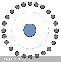
The central cathode is mild steel, 12 mm dia and the outer anodes are graphite, 5 mm dia., qty 24. The length over which they are in opposition will
be ca. 90 mm, with a gap of ca. 18 mm between them. 100 mesh SS gauze will be placed at 12 mm from the cathode, anode distance from gauze therefore 6
mm.
Mathematical aside (comments from electronics/maths experts would be helpful!):
Consider a simplification - say the anodes are 5 by 90 mm flat plates facing 5 by 90 mm flat plates on the cathode at a distance of 18 mm, then this
gives a 1.8 cm long resistor of cross-sectional area 4.5 cm2, of which we have 24.
Using the inverse of conductivity (taken for NaCl @ 1090 K, see below) to give resistivity and then putting this into the relevant equation:
Resistance = Resistivity x (length / area) = (1/3.663) x (1.8 / 4.5) = 0.11 ohm
Now, we have 24 of these identical in parallel effectively, so:
R = R/24 = 0.0046 ohm
This seems awfully low to me - maybe that's just the case, but my maths could quite easily be wrong, or it could be an over-simplification - there's
only limited cathode surface to go round. Perhaps each 'resistor' has to be considered a wedge rather than a 1.8 cm long plate of 4.5 cm2
X-sec area, and that's more maths than I fancy at this time of night.
I'm really just looking for a ballpark figure - the only way to know for sure will be to fire the finished cell up and see what the resistance across
it is.
Data:
I've dug out the binary chloride salt reference which happens to have the 100 mol % NaCl data as part of the NaCl-CaCl2 data. Some examples
posted to save on awkward attachments, J. Phys. Chem. Ref. Data 4 871 (1975):
| Quote: | NaCl:
3.663 ohm-1 cm-1 @ 1090 K
3.774 ohm-1 cm-1 @ 1130 K
3.870 ohm-1 cm-1 @ 1170 K
NaCl-CaCl2 @ 51.8 mol % NaCl
1.183 ohm-1 cm-1 @ 830 K
1.460 ohm-1 cm-1 @ 890 K
1.638 ohm-1 cm-1 @ 930 K
2.255 ohm-1 cm-1 @ 1080 K |
So clearly conductivity driven rationale to stick with your straight NaCl melt then Tank, in addition to the oxide formation problem.
The eutectic conductivity at 1080 K is still much lower than that of straight NaCl at 1090 K so it's not just a temperature effect on the
conductivity, CaCl2 does inhibit it.
For the β-Alumina cell, I also checked out the NaCl-AlCl3 system in the same reference - 1:1 molar ratio as m.p. rapidly increases
with additional NaCl, conductivity drops off with increasing AlCl3:
| Quote: | NaCl-AlCl3 1:1 molar ratio
0.462 ohm-1 cm-1 @ 460 K
0.572 ohm-1 cm-1 @ 500 K
0.681 ohm-1 cm-1 @ 540 K |
Hear hear - well said!
|
|
|
tetrahedron
Hazard to Others
Posts: 210
Registered: 28-9-2012
Member Is Offline
Mood: No Mood
|
|
your approximation only takes into account the anode surface, but clearly, the bottleneck would be at the cathode. a better solution would be to
subdivide the cell into 24 identical trapezoids, each having a side of length 1.2cm * pi / 24 (cathode contribution to a single "resistor") and an
opposite side of length 0.5cm (one anode for each "resistor"), parallel at a distance of 1.8cm. a single trapezoid is then a series of slices
(geometrically parallel to anode and cathode), thus (by the formula for resistors in series, here an infinite series)
Rsingle = integral01.8cm resistivity / {9cm * [x * 0.5cm / 1.8cm + (1 - x / 1.8cm) * (1.2cm * pi /
24)]} dx
=~ 0.5058 * resistivity * cm-1
=~ 0.1381ohm
using your value for the conductivity, or 0.005753ohm for the whole setup (ok, that's only 25% higher than your result). yes, molten salts are amazing
conductors. however, keep in mind that you'll first have to reach the redox potential before any current can flow at all.
[Edited on 16-10-2012 by tetrahedron]
|
|
|
12AX7
Post Harlot
Posts: 4803
Registered: 8-3-2005
Location: oscillating
Member Is Offline
Mood: informative
|
|
Keep in mind also the resistivity of metals generally goes way up with temperature. Copper has a bad enough tempco that, by the time it's melting, it
looks like iron. That, and the electrode interface, are probably the dominant sources of voltage drop. Still seems like a lot; hot cells always seem
to have something like 5 to 20V across them. Could the redox potentials themselves be vastly different at elevated temperature? I should think
that's a negative tempco though; heat drives dissociation. How about graphite's chlorine overpotential (if any)?
Tim
|
|
|
Dave Angel
Hazard to Others
Posts: 128
Registered: 22-3-2005
Location: UK
Member Is Offline
Mood: 0 K
|
|
Great responses - thanks both.
| Quote: Originally posted by tetrahedron | Rsingle = integral01.8cm resistivity / {9cm * [x * 0.5cm / 1.8cm + (1 - x / 1.8cm) * (1.2cm * pi /
24)]} dx
=~ 0.5058 * resistivity * cm-1
=~ 0.1381ohm |
I had this feeling in my bones that an integral would be required and you clearly have a better grasp of them than I ever had. Indeed, the cathode is
the bottle neck, but this relatively low resistance is still tolerable. I might be able to squeeze a further 10 or 20 mm out of the length of the
electrodes so the final value should be even more favourable.
| Quote: Originally posted by 12AX7 | | Keep in mind also the resistivity of metals generally goes way up with temperature. Copper has a bad enough tempco that, by the time it's melting, it
looks like iron. |
National Bureau of Standards publication 260-90 gives some data for SS up to just over 1000 K; ca. 120 x10-8 ohm m at what appears to be
1100 K - this from page 42:
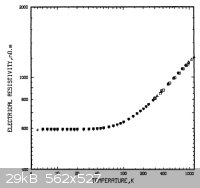
My trusty 'Nuffield Advanced Science Book of Data' states (page 133) that iron has a resistivity of 122 x10-8 ohm m at 1473 K. I can't find
any data for mild steel, but even its resistivity is double these figures or even, anomalously, say 2 to 3 powers of 10 higher, I'm not particularly
worried.
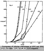
I found a snip from Google Books - Industrial Electrochemistry (D. Pletcher, F.C. Walsh), page 178:
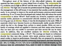
It refers to the chlor-alkali process rather than molten salt electrolysis, but states a Cl2-graphite overpotential of 500 mV, which points
us in the right direction. The graphite-chlorine overpotentials here are shown to drop in going from 25 to 70 °C, so we might assume a greater beneficial result at significantly elevated temperatures
- relevant image from the site attached to save everyone a tab:
Given the data gathered so far, I'm fairly confident that a little over 8 V across the cell as specced should suffice. A major area that we have no
immediate data on is the reduction potentials at elevated temperatures - let's hope it's a favourable effect as you've described Tim,
until data is found - or generated
|
|
|
| Pages:
1
..
15
16
17
18 |
|


