| Pages:
1
..
4
5
6
7 |
Xenoid
National Hazard

Posts: 775
Registered: 14-6-2007
Location: Springs Junction, New Zealand
Member Is Offline
Mood: Comfortably Numb
|
|
Sorry to dredge up an old thread....
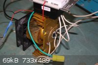
I was at a recycling centre today (God, I love these places) and I picked up an old electric radiator (heater). What I was especially atracted to were
the 3 identical heating elements. They are the silky silica tube type with coiled resistance wire down the centre and are about 45 cm. long. The
heater doesn't look like it's had much use so they are in good condition. The heater was rated at 2400 watts so they are each 800 watts. I'm thinking
of cutting each one in half or thirds, leaving the wire intact, and using them around the inside of a small muffle furnace/kiln, hopefully able to
reach about 1000 oC.
My current thinking is something like a small microwave oven shell, lined with firebrick or sillimanite slabs, with the shortened elements fitted into
holes and lining the interior.
Early days on this, I'll let it simmer for a while before doing anything rash, but any ideas on utilisation would be appreciated!
Image shows the 3 elements, heavy duty 3 way switch, silicone covered wires, etc. after dismantling.
Regards, Xenoid

|
|
|
497
National Hazard
Posts: 778
Registered: 6-10-2007
Member Is Offline
Mood: HSbF6
|
|
so i had an idea about making an induction furnace (this thread seems like the most relevent): use a electronic fluorescent ballast. would it work? i
know they make 30-50 kHz which should work pretty good. i like the idea because it looks like a pain in the ass to engineer and put together the tank
circuit and all that other jazz needed to build one from scratch... obviously a ballast isn't meant to power a big inductor so maybe doing so would
fry it, that's waht i really need to know.
|
|
|
Twospoons
International Hazard
Posts: 1281
Registered: 26-7-2004
Location: Middle Earth
Member Is Offline
Mood: A trace of hope...
|
|
You'd do better to modify a bench-top induction cooker - you know, the portable sort you plug into the wall, and takes one pot. They can be had very
cheap second hand, and they're usually good for a kW or two. You'd be lucky to find a fluoro ballast that will do more than 50W.
Helicopter: "helico" -> spiral, "pter" -> with wings
|
|
|
497
National Hazard
Posts: 778
Registered: 6-10-2007
Member Is Offline
Mood: HSbF6
|
|
ugh.. the problem with that is those cookers are very hard to get if not impossible where i am.. if i could i would love to use one. and actually i
might be able to get a couple ballasts that drive two 8 foot tubes each. still not too powerful though. i'm not sure what other alternatives there
are.
|
|
|
12AX7
Post Harlot
Posts: 4803
Registered: 8-3-2005
Location: oscillating
Member Is Offline
Mood: informative
|
|
You're welcome to try, say, hooking up a ballast to some coils.
But you'll go through a lot of ballast units and fuses doing it.
Tim
|
|
|
quest
Hazard to Self
Posts: 75
Registered: 15-9-2003
Member Is Offline
Mood: No Mood
|
|
old post, new question =]
Hi all, I want to build an electric furnace and I have some questions. I guess it's better to use this 5 years old thread rather than open a new one.
the furnace I want to build is a 12 c"m ID furnace, mostly it will be used to melt 1 kilo batch of magnalium in a batch using tin can as a vessel for
the melted metal.
I have few questions:
1) Most of the people in here used 1m"m Kanthal A-1 wire, I can get this wire in almost any size. In my furnace should I use the 1 m"m wire or a
wider/thinner wire will be better?
2) For a "power supply" I wan't to use ordinary dimer used as a switch for light bulb in my house. on the dimer it said "800W" and when I opened it I
saw a fuse of 4 Ampere in it. The problem is I'm not sure how long my wire should be for me to use this dimer with out ruining the 4A fuse, but still
use its max
capacity (800W)?
how I tried to calculate the wire length:
P = (V^2)/2R = (I^2*R)/2
V=240V, I=4A (max A before fuse burn)
R=V/I=240/4=60 ohm
1m"m kanthal wire have a resistance of 1.76 ohm/meter.
X(wire length) = 60/1.76 = 34 meters(!)
sound too big for my small 12c"m ID furnace  , and from my understanding of
electricity any shorter wire will have have less resistance ,hence more current, and will burn my 4A fuse. , and from my understanding of
electricity any shorter wire will have have less resistance ,hence more current, and will burn my 4A fuse.
3) will a 800W be enough to make an amateur electric furnace for melting 1 kilo magnalium? will it be enough to get to 1000 degrees Celsius and melt
copper? glass? (just for the science of it)
thanks,
matan.
|
|
|
Magpie
lab constructor
Posts: 5939
Registered: 1-11-2003
Location: USA
Member Is Offline
Mood: Chemistry: the subtle science.
|
|
Also see:
http://www.sciencemadness.org/talk/viewthread.php?tid=9705&a...
The single most important condition for a successful synthesis is good mixing - Nicodem
|
|
|
watson.fawkes
International Hazard
Posts: 2793
Registered: 16-8-2008
Member Is Offline
Mood: No Mood
|
|
Quote: Originally posted by quest  | | Most of the people in here used 1m"m Kanthal A-1 wire, I can get this wire in almost any size. In my furnace should I use the 1 m"m wire or a
wider/thinner wire will be better? |
There's a reason why resistance wire is available in a really huge number
of sizes, including (I've seen) half-gauge increments. The basic rule is that you take your supply voltage as fixed and your power (wattage)
requirements as a given. That gives you a total resistance you need. So for each gauge of wire, you can compute the length you'll need.
There are practical limits on the specific surface power (W/m^2) that resistance wire can withstand without failing. Get resistance wire white hot in
ordinary atmosphere, it will burn out. Don't do that. The effect of this is to put a minimum diameter requirement on your wire. Using the very
smallest diameter wire reduces direct material costs, but also boost specific surface power and reduces service life. Depending on your application,
you may want to derate your wire a couple of gauge sizes to compensate.
|
|
|
quest
Hazard to Self
Posts: 75
Registered: 15-9-2003
Member Is Offline
Mood: No Mood
|
|
thanks. now I understand it better.
one more question - how do you connect kanthal wire if it brake or if you want to connect number of kanthal coils togather? the wire will get to about
1000 degree celsius, so I can't just weld it.
|
|
|
Magpie
lab constructor
Posts: 5939
Registered: 1-11-2003
Location: USA
Member Is Offline
Mood: Chemistry: the subtle science.
|
|
| Quote: Originally posted by quest |
how do you connect kanthal wire if it brake or if you want to connect number of kanthal coils togather? the wire will get to about 1000 degree
celsius, so I can't just weld it. |
Use a stainless steel crimp, available at hardware stores.
[Edited on 15-9-2011 by Magpie]
The single most important condition for a successful synthesis is good mixing - Nicodem
|
|
|
watson.fawkes
International Hazard
Posts: 2793
Registered: 16-8-2008
Member Is Offline
Mood: No Mood
|
|
| Quote: Originally posted by quest | | how do you connect kanthal wire if it brake or if you want to connect number of kanthal coils togather? the wire will get to about 1000 degree
celsius, so I can't just weld it. |
I agree with Magpie. Use a crimp.
But you can weld it if you'd rather. Welding temperature is hotter than 1000 °C for Kanthal alloys. Rather than explain it myself, here's a
link to a document by a guy who's done it: http://rick.sparber.org/Articles/we.pdf.
|
|
|
Endo
Hazard to Others
Posts: 124
Registered: 5-1-2006
Location: USA
Member Is Offline
Mood: Cold
|
|
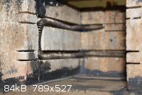
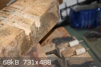
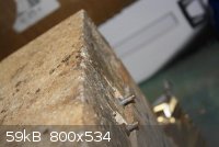
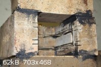
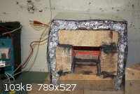
Using firebrick and a tile saw I was able to cut some channels to hold a nichrome element salvaged from an element for an electric furnace. I also
used the insulators left from the element. The dimensions inside are 6 1/2 inches deep, 4 1/2 inches tall and 4 1/2 inches wide. I picked up a tube
of refractory cement for 5$ (good to 1100C, comes in a caulking tube) and assembled all but the top brick in back. I notched the top back brick to
take the insulators and decided to leave it unmoartared in case I have to change the wire out. I intend to wrap the whole brick center in a layer of
fiberglass insulation (cheap) and then bend a sheet metal case for it. So far the door will just be two firebricks moartared together. It has gone
together pretty easy. I hooked it up to 120V and it pulls 16 amps through an Ammeter I didn't let it get really hot because the cement wasn't
completly cured yet, so it may drift a bit as it heats up. This puts the output at 1920W. I need some way to control the temp... Will a light
dimmer work or will it just burn up? Back in this thread I saw a diagram for a simple control circuit but it was 220V. I also have a switch from an
electric range, but it is 250V 4.8 - 6.4Amps. I would like more control and I am unsure if this could control a circuit at 120V. Any good
suggestions about how to control the electrical without spending more than ~20$?
[Edited on 20-1-2012 by Endo]
|
|
|
Magpie
lab constructor
Posts: 5939
Registered: 1-11-2003
Location: USA
Member Is Offline
Mood: Chemistry: the subtle science.
|
|
| Quote: Originally posted by Endo | | ... I was able to cut some channels to hold a nichrome element salvaged from an element for an electric furnace. |
Just out of curiosity what was the voltage specified for the electric furnace you salvaged?
The single most important condition for a successful synthesis is good mixing - Nicodem
|
|
|
Endo
Hazard to Others
Posts: 124
Registered: 5-1-2006
Location: USA
Member Is Offline
Mood: Cold
|
|
4.8 KW at 240V. It looked a lot like the element used
http://www.sciencemadness.org/talk/viewthread.php?tid=9705&a...
about half way down to load test. I have four of them in new condition.
[Edited on 20-1-2012 by Endo]
|
|
|
Magpie
lab constructor
Posts: 5939
Registered: 1-11-2003
Location: USA
Member Is Offline
Mood: Chemistry: the subtle science.
|
|
OK, then you are apparently taking elements that were designed for 240V and applying 120V to them. I don't have any problem with that.
The single most important condition for a successful synthesis is good mixing - Nicodem
|
|
|
Endo
Hazard to Others
Posts: 124
Registered: 5-1-2006
Location: USA
Member Is Offline
Mood: Cold
|
|
I guess I was just going to be lazy and not run the wire and buy the breaker to hook up 240V supply into my basement. Is it harder to buy/build a
control for 16 amps at 120 vs 8 amps at 240?
|
|
|
watson.fawkes
International Hazard
Posts: 2793
Registered: 16-8-2008
Member Is Offline
Mood: No Mood
|
|
| Quote: Originally posted by Endo | | I guess I was just going to be lazy and not run the wire and buy the breaker to hook up 240V supply into my basement. Is it harder to buy/build a
control for 16 amps at 120 vs 8 amps at 240? |
Easiest control at this level is an appliance controller, as
for a stove or oven. Easy to find as a replacement part. If there's an appliance refurbisher in your area, they'll have buckets of them in their shop.
You might have something of a hard time finding a current rating of 16A @ 120V, as such appliances are almost always run on 240V.
You should be aware that your elements are going to run at 1/4 power unless you center-tap the elements you have. If you use the elements at half
their original length, you could also wire it as a two-zone oven with two controllers.
|
|
|
Endo
Hazard to Others
Posts: 124
Registered: 5-1-2006
Location: USA
Member Is Offline
Mood: Cold
|
|
I was aware I wasn't going to get that high of a wattage from this element. I ended up using about 3/4 of the length of the element when I wired the
furance. I wanted around 1500 to 2000 watts so I wouldnt have to worry about a higher amperage breaker, (it is on a 20 amp breaker now)
I do have a controller from an electric range. However it is typical of most electric range controllers and its lowest setting just after off is 4.8
Amps, then it can be adjusted on up to the limit of the controller. Could I use both legs of the electric range controller to increase the handled
amperage of the controller, in a sense put the same phase 120 volts to the L1 and L2 terminals, and run both the H1 and H2 to the element, with the
neutral going directly to the other end of the element.
Is there any way to use a pair of 1000 watt dimmer switches in parallel? or will the differences in load handling burn one of them out? Could i put
something in the circuit with dimmer switches to prevent them from having the problem with having too much load on them and not being able to evenly
balance the load between the two of them.
|
|
|
johansen
Harmless
Posts: 27
Registered: 25-6-2011
Location: United States
Member Is Offline
Mood: No Mood
|
|
the controllers from electric ranges are typically thermal circuit breakers with adjustable spring tension, the on time is proportional to current
squared, off time is relatively constant. You can pull a little more current than they are rated, but its easy to burn them out.
Short answer is no, you can't wire the dimmers in parallel.
As Watson suggested you could center tap the element you have now, each with its own 1000watt dimmer.
As far as I know, the Triac in a 1000 watt dimmer is probably rated for 20 amps, the 1000 watt limit is more of a thermal dissipation problem when
confined to a 20 cubic inch electrical box w/o airflow. the 600 watt dimmers typically have a 10 or 15 amp rated triac.
|
|
|
Endo
Hazard to Others
Posts: 124
Registered: 5-1-2006
Location: USA
Member Is Offline
Mood: Cold
|
|
@Johansen
Ok so In a pinch I could buy a 1000 watt dimmer, dissassemble the case and look up the rating on the triac(s) inside, if it can handle the amperage I
then add a heat sink. Otherwise the center tap (breaking the element into two elements) and dual heat zones with a pair of dimmers is the way to go.
Thanks for your reply and help... I will admit that I am not very knowledgable with the electronics.
|
|
|
Magpie
lab constructor
Posts: 5939
Registered: 1-11-2003
Location: USA
Member Is Offline
Mood: Chemistry: the subtle science.
|
|
If I understand you right you have one shortened element which draws 16 amps at 120V. If you cut that in half and make two equal sized shorter
elements you will then draw 32 amps through each element. I don't think you want to do that, do you?
This is what I think you are talking about :

I think watson was just telling how to obtain the full power of the element using 120V instead of the 240V when mentioning the center tap (correct me
if I'm wrong here, watson).
What I think we arrived at was a circuit like this pending the successful use of the 1000w dimmer:

This will allow you to keep the same 16amps which, as you say, will keep within your wiring/circuit breaker limitations but still give you 2000w.
[Edited on 21-1-2012 by Magpie]
The single most important condition for a successful synthesis is good mixing - Nicodem
|
|
|
johansen
Harmless
Posts: 27
Registered: 25-6-2011
Location: United States
Member Is Offline
Mood: No Mood
|
|
Now that i re-read your post, its clear you have a 16 amp at 120vac element in it now.
--no reason to center tap it then.
I'm not sure what a 1000w dimmer costs these days but i would just go ahead and hook it up.
if you blow the triac you can get a 30 amp unit for $3.00 on mouser.com, or anywhere else (S+H will cost more than the part)
|
|
|
watson.fawkes
International Hazard
Posts: 2793
Registered: 16-8-2008
Member Is Offline
Mood: No Mood
|
|
This problem is just an application of Ohm's law. V=IR and P=I^R=V^2/R. If you put half the
voltage across a resistor, it draws half the current and dissipates one quarter of the power. The controller has to be rated larger than the current
draw, but that current is determined by the load, not by the controller. At the original rating, R = 12 Ω and I = 20 A.
To compute the power draw at half the voltage, V_1 / V_0 = 1/2, and three fourths of the resistance R_1 / R_0 = 3/4, we get a factor of
(1/2)^2/(3/4)=1/3, so the power draw is 4.8 kW / 3 = 1.6 kW. R= 9 Ω and I = 13.1/3 A. Therefore, in this configuration, a 10A controller is
insufficient.
|
|
|
White Yeti
National Hazard
Posts: 816
Registered: 20-7-2011
Location: Asperger's spectrum
Member Is Offline
Mood: delocalized
|
|
These furnaces look amazing! They make me want to make my own. Right now, I use a wood stove for my inorganic syntheses.
In my kitchen there's an old electric stove/oven that might soon fall apart. That's raw material for an electric furnace.
"Ja, Kalzium, das ist alles!" -Otto Loewi
|
|
|
Endo
Hazard to Others
Posts: 124
Registered: 5-1-2006
Location: USA
Member Is Offline
Mood: Cold
|
|
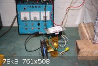
Well, I found 1000Watt Dimmers for $7.50 each online. It showed up monday and I had time to mess with it today. The Triac inside is a BTA25-600B
Looking up the spec sheet it is indeed rated up to 25 amps. A quick try with the back cover of the dimmer switch off had the small copper plate heat
sink getting too hot to touch in the course of about two minutes.
I dug through some stuff and found an old heat sink from an Athalon Thunderbird processor and drilled it to mount the triac. Screwed it down with a
layer of thermal paste. Soldered some wires to get some working room from the dimmer an gave it a shot. I found an old computer PSU fan and wired it
up to blow across the heat sink.
The system seems to work very well. I just ran it for 20 min and the heat sink was barely warm to the touch. I can control the heater down to where
the element is just warm, and up to bright cherry red. 4.5 amps to 15.5 amps on the ammeter.
I took a few pics of the furnace and heat sink. Also wrapped the furnace in pink insulation then aluminum foil. Then made a box out of left over
ductwork scraps (I know it isn't pretty but it works  ) I stuffed the back and
corners with more insulation and closed it all up. ) I stuffed the back and
corners with more insulation and closed it all up.
|
|
|
| Pages:
1
..
4
5
6
7 |


