| Pages:
1
2
3
4
..
10 |
Bert
Super Administrator

Posts: 2821
Registered: 12-3-2004
Member Is Offline
Mood: " I think we are all going to die. I think that love is an illusion. We are flawed, my darling".
|
|
Quote: Originally posted by Ral123  | | I've tried it, the plastic NC particles need a little initial kick, like from LS or may be some cotton NC. |
Are you referring to having difficulty igniting the plasticized NC?
Dense, colloided NC powders are generally a LOT more difficult to ignite than black powder, new primer compound technologies were required to go with
these new propellants-
Look at primer pellet compositions intended for modern powders. Ingredients to enhance ignition from both hotter flames than the old fulminate &
chlorate mix caps/primers and others to produce hot burning particles. Ingredients like Antimony sulfide, Lead thiocyanate, tetryl, PETN and TNT,

A bag of BP placed over the percussion or electric primer is used as an igniter charge for the NC propellent in a lot of artillery applications.
During the transition from BP to NC, some cartridges for rifle and pistol were also loaded with BP mixed with various forms of NC, as in Du Pont's
"Lesmoke" powder- They just added nitrated sawdust right into what was essentialy BP during manufacture.
Other transition period cartridges were loaded with both black powder and smokeless/semi smokeless powders together in a variety of techniques for
various reasons including enhanced velocity, accuracy and improved fouling/cleaning characteristics.
http://castboolits.gunloads.com/showthread.php?137201-Black-...
[Edited on 3-3-2014 by Bert]
Rapopart’s Rules for critical commentary:
1. Attempt to re-express your target’s position so clearly, vividly and fairly that your target says: “Thanks, I wish I’d thought of putting it
that way.”
2. List any points of agreement (especially if they are not matters of general or widespread agreement).
3. Mention anything you have learned from your target.
4. Only then are you permitted to say so much as a word of rebuttal or criticism.
Anatol Rapoport was a Russian-born American mathematical psychologist (1911-2007).
|
|
|
Hennig Brand
International Hazard
Posts: 1284
Registered: 7-6-2009
Member Is Offline
Mood: No Mood
|
|
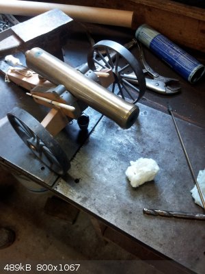
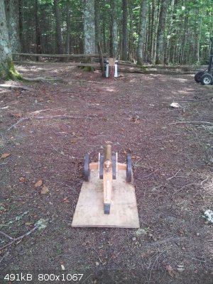
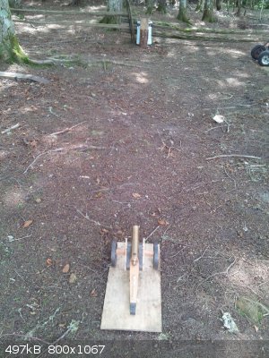
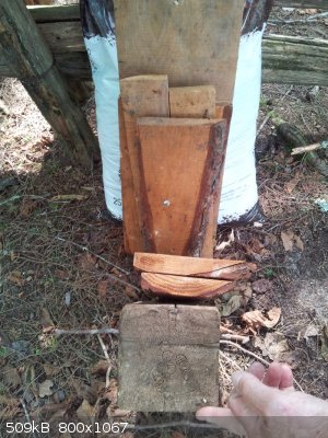
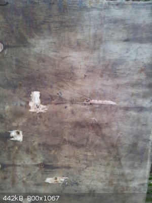
Was firing a homemade brass cannon this afternoon and I thought I would post a few pictures. Homemade nitrocellulose was used for three shots and
commercial FFFG black powder was used for another three shots. The projectiles were 0.45 cal. lead balls.
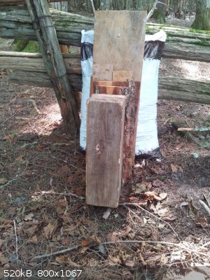
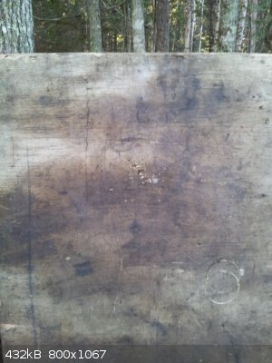
Included are a few pictures taken showing the penetration of one of the shots where the homemade nitrocellulose was used. About 2.6g of nitrocellulose
was used as propellant and the lead ball penetrated a 5" spruce block and two 1 inch hemlock boards. A later shot used 2.2-2.5g of commercial FFFG
black powder and the ball made it less than 2 inches into the spruce block, as shown in the last picture. This really shows the incredible difference
between these two types of propellants. The nitrocellulose used was not nearly as highly nitrated as it could have been either. Black powder is a lot
of fun though and it does have its uses. It is much easier to make black powder with reasonably consistent performance and storage stability, than it
is with smokeless powder, which is one big advantage.
[Edited on 3-8-2014 by Hennig Brand]
"A risk-free world is a very dull world, one from which we are apt to learn little of consequence." -Geerat Vermeij
|
|
|
NeonPulse
Hazard to Others
Posts: 417
Registered: 29-6-2013
Location: The other end of the internet.
Member Is Offline
Mood: Isolated from Reality! For Real this time....
|
|
Very nice! How big is the barrel? Sure packs a punch judging by the penetration there, could you recover the round or was it shattered? I actually am
working on something similar but on a much smaller scale to fire 6mm fishing sinkers Its going to be mounted on a solid lead block though. That is
when time allows me to pursue the hobby....
|
|
|
Hennig Brand
International Hazard
Posts: 1284
Registered: 7-6-2009
Member Is Offline
Mood: No Mood
|
|
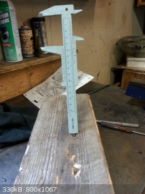
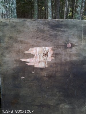
The barrel is slightly larger than the 0.45 cal. lead ball projectiles. Cotton patches were used to create a tight fit between the balls and the
barrel. The bottom picture on the left shows the ball, still intact, stuck to the third hemlock board. On close inspection the ball was flattened a
bit, but still completely intact. I believe these balls were made from wheel weights, so antimony hardened lead.
"A risk-free world is a very dull world, one from which we are apt to learn little of consequence." -Geerat Vermeij
|
|
|
nitro-genes
International Hazard
Posts: 1048
Registered: 5-4-2005
Member Is Offline
|
|
NC surely is a better propellant as BP regarding gasoutput etc, though the huge difference between NC and BP in your test is mainly due to the
relatively short barrel. With long enough barrel and fast BP very high muzzlevelocities can certainly be reached!
|
|
|
Ral123
National Hazard
Posts: 735
Registered: 31-12-2011
Member Is Offline
Mood: No Mood
|
|
As far as I know, a bottleneck from the chamber to the barrel is needed to achieve high velocities with any propellant. Nitrated cotton is awesome
propellant if it wasn't for the detonation danger. I wonder if highly nitrated cotton can be used as ignitor for smokeless powder instead of lead
styphnate.
|
|
|
Hennig Brand
International Hazard
Posts: 1284
Registered: 7-6-2009
Member Is Offline
Mood: No Mood
|
|
I think typical muzzle velocities for black powder rifle is around 1200 to 1500 fps. Rifles using nitrocellulose based propellant can reach muzzle
velocities of 4000 fps or even higher. The kinetic energy equation is E=1/2mv^2, so doubling the velocity will result in a 4 times energy increase.
One of the main reasons black powder arms had such heavy calibers (large bullets) was because they were trying to increase the energy of the round by
increasing the mass. Doubling the mass only results in double the kinetic energy for a given velocity though. They did this mostly because they were
limited in the amount of velocity they could get from the black powder propellant used at the time. The other reason, in the case of ball projectiles,
was that the losses due to wind resistance were much larger with a ball as compared to a conical projectile of the same mass. A larger ball, like a
conical projectile, had a much better (smaller) surface area to volume/mass ratio therefore less losses due to wind resistance as well. Less losses
due to wind resistance meant that more of the energy/velocity that was present at the time the projectile left the barrel of the gun was still present
once it made it to the target. Ball projectiles fired from black powder muskets, etc, in years gone by often had very little energy left in them even
at fairly modest ranges. I will have to dig for a reference but even in extremely long and huge naval guns, when using black powder, they were only
able to obtain ranges a fraction of what could be obtained with nitrocellulose (about 8 miles range IIRC).
[Edited on 3-8-2014 by Hennig Brand]
"A risk-free world is a very dull world, one from which we are apt to learn little of consequence." -Geerat Vermeij
|
|
|
roXefeller
Hazard to Others
Posts: 463
Registered: 9-9-2013
Location: 13 Colonies
Member Is Offline
Mood: 220 221 whatever it takes
|
|
In a simplified model, wind losses are proportional to rho*v^2, with the proportionality constant being related to the aerodynamic profile of the
object and is independent of the mass of the projectile (rho is the fluid density). Ballisticians who are concerned with the final energies of the
bullet will fire a heavier bullet at the same speed (requiring a higher muzzle energy) because it sees the same drag forces (and the same terminal
velocity) as the lighter bullet but still has extra mass to contribute to the (mv^2)/2 kinetic energy.
|
|
|
Hennig Brand
International Hazard
Posts: 1284
Registered: 7-6-2009
Member Is Offline
Mood: No Mood
|
|
Unless we are changing the density of the material, changing the mass will change the cross sectional area of the projectile. I don't remember doing
much of this sort of thing in school, so I am learning as I go here.
The following was taken from "Engineeringtoolbox.com"
"Drag force can be expressed as:
Fd = cd * 1/2 * ρ * v^2 * A
where
Fd = drag force (N)
cd = drag coefficient
ρ = density of fluid (1.2 kg/m^3 for air at NTP)
v = flow velocity
A = characteristic frontal area of the body
The drag coefficient is a function of several parameters like shape of the body, Reynolds Number for the flow, Froude number, Mach Number and
Roughness of the Surface.
The characteristic frontal area - A - depends on the body."
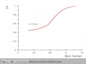
Found a graph and a table which should help compare a spherical projectile to a modern high performance rifle projectile. The graph was taken from, http://arc.id.au/CannonballDrag.html, which is a webpage that does a great job of explaining drag on spherical projectiles. The following is the
text which preceded the graph.
"Drag Near the Speed of Sound
The speed range of interest for smooth bore guns is from ~100 m/sec to ~700 m/sec, since the speed of sound is ~340 m/sec, this corresponds to a range
of Mach numbers from 0.3 to 2.0, so the additional forces associated with projectiles travelling near the speed of sound will be significant.
Fig 2 shows a plot of the drag coefficient as a function of Mach number for spheres ranging in diameter from 2.5 mm to 12.5 mm. The curve is a manual
fit to chronograph data [Miller & Bailey, 1979]. The rapid increase in drag as a function of Mach number at velocities near the speed of sound is
clear."
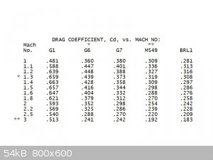
The table comes from, R.L. McCoy's Modern Exterior Ballistics, and the bullets shown are apparently common high powered rifle bullets (modern low drag
bullets).
Energy/Work = Force * Distance = Drag * Distance of Bullet Travel
Since velocity and drag coefficient change during bullet flight, which changes the drag force, it makes for an interesting problem. Would be easy to
do with a computer. Manually the bullet flight could be broken up into small increments and an average value for work done on the bullet by the drag
force for all increments could be found. This would give an approximate answer with the accuracy dependant on how many increments were taken.
[Edited on 4-8-2014 by Hennig Brand]
"A risk-free world is a very dull world, one from which we are apt to learn little of consequence." -Geerat Vermeij
|
|
|
roXefeller
Hazard to Others
Posts: 463
Registered: 9-9-2013
Location: 13 Colonies
Member Is Offline
Mood: 220 221 whatever it takes
|
|
| Quote: |
Since velocity and drag coefficient change during bullet flight, which changes the drag force, it makes for an interesting problem. Would be easy to
do with a computer. Manually the bullet flight could be broken up into small increments and take an average value. Adding up the increments, could
give an approximate answer with the accuracy dependant on how many increments were taken.
|
It's a nonlinear differential equation and can be solved with standard methods. Starting at F = ma, -b*v^2 = m*dv/dt, m*dv/dt + b*v^2 = 0, dv/dt +
(b/m)v^2 = 0, integrating: Sdv/v^2 = -b/m Sdt - C/m, -1/v = (-bt-C)/m, v = m/(bt+C), C = m/v_o if my calculus didn't fail me. I'll let you perform
the dx/dt integration for speed drop vs distance, it looks logarithmic. So if you stop and examine the b/m coefficient of the diff eq dv/dt +
(b/m)v^2 = 0, overall reductions reduce the drag term (diminished b or enlarged m, or if m is increasing at a faster rate than b). Fat men coast
better downhill on bikes. It is a simplified model (you could add the velocity dependence of b(v) and then go to a differential equation solver), and
I'm generally referring to low drag rifle bullets where the length (mass) of the bullet means a bit less to drag than the front taper and the rear
flow separation point. That explains why I was claiming that mass can increase without significant drag increase.
As far as proximity to sonic transition, rifles are generally supersonic. It is usually better to strike the target before the bullet transitions
because instabilities at transition cause random variations in trajectory and misses.
[Edited on 4-8-2014 by roXefeller]
|
|
|
Hennig Brand
International Hazard
Posts: 1284
Registered: 7-6-2009
Member Is Offline
Mood: No Mood
|
|
I should have just said to add up the losses for the increments, to get the total lose in the above quote.
This kind of thing, from what I have read in the last day or so, is generally considered very complex. Your math seems correct for the simplified
model, though calculus was not my favorite subject in school. The ballistic coefficient will change a lot with velocity, as you can see by looking in
the above tables, but the change does look to change fairly linearly with velocity, though the slope does change at a point below the speed of sound.
With spherical projectiles the mass has a much greater effect on drag and losses than in low drag conical projectiles and spherical projectiles is
what the cannon in the above test used. With spherical projectiles the ballistic coefficient is much larger in magnitude and changes much more with
respect to changes in velocity than for conical projectiles, once again though the change is fairly linear apparently with respect to velocity. I
guess the best way to say it, IMO, is that heavier/larger projectiles, for a given material, have more energy for a given velocity and lose a smaller
proportion of their energy as a result of drag during flight. Also modern conical projectiles, mostly because of smaller radial cross sectional area
with respect to mass, but also other more subtle aerodynamic improvements in shape, lose a much smaller proportion of their energy for a given
distance traveled than spherical projectiles of the same mass. This all assumes all projectiles are made from the same material with the same density.
[Edited on 4-8-2014 by Hennig Brand]
[Edited on 15-9-2014 by Bert]
"A risk-free world is a very dull world, one from which we are apt to learn little of consequence." -Geerat Vermeij
|
|
|
Dornier 335A
Hazard to Others
Posts: 231
Registered: 10-5-2013
Location: Northern Europe
Member Is Offline
Mood: No Mood
|
|
I wrote a simple Python program a while ago to simulate projectile trajectories in the atmosphere. It is based on the formula Henning Brand posted
earlier:
Fd = cd * 1/2 * ρ * v2 * A
It calculates the changes in x and y velocity every millisecond. I added the air's change in density by altitude for simulations of long range
artillery but not how cd changes with speed.
I could post the code if anyone wants; it's only 30 lines or so.
|
|
|
Manifest
Script Kiddie Asshole
Posts: 229
Registered: 7-12-2012
Member Is Offline
Mood: No Mood
|
|
| Quote: Originally posted by Dornier 335A | I wrote a simple Python program a while ago to simulate projectile trajectories in the atmosphere. It is based on the formula Henning Brand posted
earlier:
Fd = cd * 1/2 * ρ * v2 * A
It calculates the changes in x and y velocity every millisecond. I added the air's change in density by altitude for simulations of long range
artillery but not how cd changes with speed.
I could post the code if anyone wants; it's only 30 lines or so. |
Sure, why not show off your work.
|
|
|
Dornier 335A
Hazard to Others
Posts: 231
Registered: 10-5-2013
Location: Northern Europe
Member Is Offline
Mood: No Mood
|
|
Here's the code:
| Code: |
from math import sin,cos,e,radians,atan2,sqrt,pi

α = 30 #Angle of elevation (degrees)
V = 25 #Muzzle velocity (m/s)
M = 0.0027 #Projectile mass (kg)
R = 2 #Projectile radius (cm)
cd = 0.42 #Drag coefficient (0.42 for spheres)
y = 0 #Elevation (m)

x = 0
Vx = V*cos(radians(α))
Vy = V*sin(radians(α))
A = 0.0001*pi*R**2

def FD():
    ρ =  2.831/(1 + 1.3262*e**(0.1516*y/1000)) #Density of the air
    return 1/2*V**2*ρ*cd*A #Calculate drag force

for t in range(300000):
    x += Vx*0.001 #Move the projectile
    y += Vy*0.001
    Fd = FD()
    Fx = Fd*cos(atan2(Vy,Vx))
    Fy = Fd*sin(atan2(Vy,Vx))

    Vy -= (0.00982 + Fy/(1000*M)) #Velocity changes
    Vx -= Fx/(1000*M)
    V = sqrt(Vy**2+Vx**2) #Speed
    if round(t/100,1) == t/100: #Print position every 100 ms
        print(x,y,Vy)
        pass
    if y <= 0 and Vy < 0: #Print position when landed
        print(x,y)
        break
|
|
|
|
Hennig Brand
International Hazard
Posts: 1284
Registered: 7-6-2009
Member Is Offline
Mood: No Mood
|
|
Nice bit of code you have there. I only took one first year computer science course, but it was clear even from the limited exposure I had that it was
a great way to make very powerful tools for processing massive amounts of data. We mostly used Matlab in the course I took.
I just made up an Excel spreadsheet which should be useful for small cannon, etc, firing spherical projectiles. The above equation for drag force and
the kinematic equations of motion were used. An equation for the ballistic coefficient was obtained from a Master’s thesis called, "Ballistics of
17th Century Muskets", by Dr. David Miller and the data and methods he used came from earlier more well established references.
Fd = cd * 1/2 * ρ * v^2 * A
where
Fd = drag force (N)
cd = drag coefficient (unitless)
ρ = density of fluid (1.2 kg/m^3 for air at NTP)
v = flow velocity
A = characteristic frontal area of the body

Cd = 0.107 + 2.08*10^-3 * v
where
Cd = ballistic coefficient (unitless)
v = projectile velocity in m/s
a = F/m
where
a = acceleration in m/s^2
F = force in N
m = mass in kg
k = 1/2 * m * v^2
where
k = kinetic energy
kinematic equations
d = v * t
v = vo + at
Volume of sphere
V = 4/3 * pi * r^3
Cross sectional area of sphere
A = pi * r^2
(Maybe a couple others too)
The values in the table assume still air (no wind), so it does not account for changes in horizontal position from point of aim, or changes in bullet
velocity as a result of increased or decreased drag in the direction of bullet travel, due to this form of windage. Drag forces were not considered
for projectile drop, from the point of aim, as the velocities are very small which means the drag forces would also be very small.
Time increments of 0.001s were used, but this could be made smaller if desired for greater accuracy. Loss of accuracy comes from the fact that for
each 0.001s increment the value for deceleration due to drag forces was taken as the value at the beginning of the increment. The table was made for
up to 0.2s of flight time, but the columns can be extended if more values were desired. It can be modified if desired, or used as is by simply
changing the 5 variables highlighted in yellow. The density of lead was set as the default density for the projectile. Here is a link to a webpage
with a table showing air density versus temperature.
http://www.engineeringtoolbox.com/air-properties-d_156.html
Not too hard to tell why conical projectiles, and propellants and guns capable of higher velocities were adopted. The proportion of kinetic energy
lost even at very short range is incredible.
Keep in mind that the bullet doesn't travel in a straight line, but rather follows a parabolic path. The distances in the table are the distances
along that parabolic path. The actual horizontal range will be somewhat less, if the gun is pointed above the target (which it must be). For normal
short range shooting, the angle would be so small, that the difference in distance between the true parabolic path and an assumed straight path to the
target would be quite small. Likewise, because the angle is normally so small, the component of the muzzle velocity in line with the target would
normally be nearly the same as the full muzzle velocity.
It is possible I have made errors, if so let me know.
Attachment: Spherical Projectile Velocity & Position Table.xlsx (74kB)
This file has been downloaded 1201 times
Attachment: Spherical Projectile Velocity & Position Table (compatibility mode).xls (138kB)
This file has been downloaded 1116 times
[Edited on 6-8-2014 by Hennig Brand]
"A risk-free world is a very dull world, one from which we are apt to learn little of consequence." -Geerat Vermeij
|
|
|
Hennig Brand
International Hazard
Posts: 1284
Registered: 7-6-2009
Member Is Offline
Mood: No Mood
|
|
Cd should have been called drag coefficient, as it was above. I assumed that they were the same thing, which they are not apparently.
"A risk-free world is a very dull world, one from which we are apt to learn little of consequence." -Geerat Vermeij
|
|
|
Hennig Brand
International Hazard
Posts: 1284
Registered: 7-6-2009
Member Is Offline
Mood: No Mood
|
|
Just noticed that I forgot to take the average velocity for each increment when calculating projectile drop. Just made the minor adjustment and
attached the revised tables.
Attachment: Spherical Projectile Velocity & Position Table (Revised).xlsx (74kB)
This file has been downloaded 1052 times
Attachment: Spherical Projectile Velocity & Position Table (Revised & Compatibility mode).xls (138kB)
This file has been downloaded 1136 times
[Edited on 15-8-2014 by Hennig Brand]
"A risk-free world is a very dull world, one from which we are apt to learn little of consequence." -Geerat Vermeij
|
|
|
roXefeller
Hazard to Others
Posts: 463
Registered: 9-9-2013
Location: 13 Colonies
Member Is Offline
Mood: 220 221 whatever it takes
|
|
The topic of where in the increment you are integrating in the summation is a topic of numerical methods theories. In explicit integration schemes
this choice can affect the stability of the solver for a given increment. There is a certain amount of 'damping' of the solution error that each
position in the increment creates. It's an interesting aspect of numerical integration of ordinary differential equations that are a function of
time. That's a long winded way of saying, just because you 'feel' its somehow wrong the way you did it before, it is only one of many options for
this technique. Something to remember, 'all models are wrong, but some models are useful'.
|
|
|
Hennig Brand
International Hazard
Posts: 1284
Registered: 7-6-2009
Member Is Offline
Mood: No Mood
|
|
I see what you mean. I know that the model isn't perfect, but I think using an average velocity over each increment will increase accuracy.
"A risk-free world is a very dull world, one from which we are apt to learn little of consequence." -Geerat Vermeij
|
|
|
roXefeller
Hazard to Others
Posts: 463
Registered: 9-9-2013
Location: 13 Colonies
Member Is Offline
Mood: 220 221 whatever it takes
|
|
That is a difficult term to describe though. Since your hoping that a result matches reality, that should be said explicitly. Obviously we know that
the numeric solution is incorrect, either to one side or another of the true answer. And you attempt to hit the mark by your own feel good, best
estimate, engineering judgement approach. So at the end you reason to yourself that one improvement is more accurate than before, based, tacitly, on
how you feel the problem is setup, instead of qualifying your answer against reality. But it can be that the errors 'introduced' can actually offset
the error inherent in the integration scheme and in the end, though you feel the answer is less accurate because you knew it wasn't the best attempt,
the math and the comparison to reality says otherwise. I know this sounds ethereal and like a conspiracy theory, but what I'm getting at is a more
fundamental point; you need to base your conclusions in the end less on the subjectivity of your opinions, and more on the objectivity of comparison
to truth. An analyst can be fooled by a simulation, test technicians are less so.
Here is the text book example from numerical methods 101: when you compare the zero, first, and second order numeric integration schemes, each one has
its own error approximation. The math is more complicated with each additional order, going from point approximation, to line, to quadratic
approximation of each finite step along the path. The gut instinct is that error is reduced going from zero to first, and reduced further going from
first to second because each interpolant function more closely adheres to the function you are trying to integrate. When in fact the error in the
zero order scheme is the same as that in the second order, and the first is worse than both. You'd be better off sticking with the zero order scheme
or skipping the first and going to the second according to the error approximation. I've got other examples that aren't so basic but that one is a
good starting point. I feel like I'm saying something Rosco has been telling us repeatedly over the last year, except mine has less elegance.
Something about the conflict of truth and the opinion of the experimenter.
|
|
|
Hennig Brand
International Hazard
Posts: 1284
Registered: 7-6-2009
Member Is Offline
Mood: No Mood
|
|
If I use the kinematic equation of motion below to check the vertical drop due to gravity, neglecting air resistance for the 0.2s of flight time, I
get a total drop of 7.72441 inches. In the first table I didn't take the average velocity for each increment and the total drop came out to 7.76303
inches. In the revised table I used the average velocity over each increment to calculate distance travelled (dropped) and got 7.72441 inches, or the
same (at least to the amount of decimals shown) as that obtained when using the kinematic equation below, which is an improvement. The difference
isn't huge, but there is a difference. The biggest source of error in that part of the model, IMO, was that drag wasn't considered (constant
acceleration was assumed), but even that error would be pretty small given the low drop velocity the projectile attains in the short flight time.
d = vot + 1/2at^2
Now that I am looking at the table again, I could have done it neater by just using the kinematic equations entirely, but instead I reasoned through
it in my own way. What I did would simplify to the same thing though anyway I think.
I may have dodged the hard math by using a spreadsheet to work this out, but I think that table would be of much more use to most and the variables
are easily changed as needed producing a whole set of values. I do see where the kinematic equations come from too, using basic calculus.
[Edited on 16-8-2014 by Hennig Brand]
"A risk-free world is a very dull world, one from which we are apt to learn little of consequence." -Geerat Vermeij
|
|
|
Hennig Brand
International Hazard
Posts: 1284
Registered: 7-6-2009
Member Is Offline
Mood: No Mood
|
|
Down the Rabbit Hole a Little Farther
I spent a few more hours reading and playing around with the ballistics table and I think it is starting to become a much better model (more accurate
representation) . Launch angle of projectile was added as another variable and the velocity was broken into vertical and horizontal components. Drag
was included in all velocity calculations. I used some of the equations from the NASA site for projectile motion with drag, and one equation from the
Wiki page on drag for velocity of a free falling object through a non-dense medium. Conditional formatting was used so that when the projectile
vertical velocity is at zero, at maximum height (at end of ascent), the following values (during descent) are calculated using the equation for a
projectile in free fall. I think there should be more conditional formatting for that column, actually, because during ascent, at very low vertical
velocities, especially with low launch/firing angles, the drag force is proportional to velocity not the velocity squared. I may look into it at a
later time.
I made a pdf of the NASA page for my own notes, and included it here. I hope they don't mind. It is a very good resource they provide, with excellent
explanations to go with the equations. The equation taken from the Wiki page for vertical velocity of free falling objects including drag is as
follows:
V(t) = sqrt[(2*m*g)/(densityair * A *Cd)] * tanh[(t*sqrt{(g*densityair*Cd*A)/(2*m)}]
From Wiki: "The velocity as a function of time for an object falling through a non-dense medium, and released at zero relative-velocity v = 0 at time
t = 0, is roughly given by a function involving a hyperbolic tangent (tanh):"
BTW, I included a couple of graphs, one in metric (meters and cm) and one in Imperial or American units (feet and inches). I use both pretty much
interchangeably, but some don't. In school they had us use both. One of my first year professors, who happened to be teaching statics and dynamics
said that needing to use both sets of units was the consequence of living next door to an eight hundred pound gorilla. I thought it was funny
especially since the gentleman was from Texas.
Attachment: Flight Equations with Drag.pdf (116kB)
This file has been downloaded 1315 times
Attachment: Spherical Projectile Velocity & Position Table (Revised again).xlsx (202kB)
This file has been downloaded 1008 times
Attachment: Spherical Projectile Velocity & Position Table (Revised again & Compatibility Mode).xls (322kB)
This file has been downloaded 1267 times
Feels like I am back in school. I only took first year statics and dynamics for engineers. I guess the physics and mechanical engineering people would
have done more. It is pretty fun stuff.
Graphs of projectile position during flight can be found by scrolling to the right of the tables, in the Excel files. The flight time
displayed by the table was extended from 0.2s to 0.5s, and it can easily be extended more.
If I can get out of the city for a while I may get to do a little testing and see if I can actually hit anything using this table.
BTW, if one of us could design a good hand held laser gun it would sure simplify things. 
[Edited on 18-8-2014 by Hennig Brand]
"A risk-free world is a very dull world, one from which we are apt to learn little of consequence." -Geerat Vermeij
|
|
|
Hennig Brand
International Hazard
Posts: 1284
Registered: 7-6-2009
Member Is Offline
Mood: No Mood
|
|
I have been looking into getting a ballistic chronograph so that muzzle velocities can be measured. Without a reasonably accurate value for muzzle
velocity a ballistics table is of little use. For now I found these equations, from the following website, which allows one to obtain an estimated
muzzle velocity through calculation for black powder, smooth bore, cannons.
http://arc.id.au/CannonBallistics.html
I have attached a jpg of the final two equations, but if you go to the site there is a description, with intermediate equations, of how they arrived
at the final equations. There are also tables comparing calculated performance values and actual performance values for black powder cannon. The
calculation results are, at least from what has been reported, fairly close to actual field results in most cases.
In the equations,
m = mass of cannon ball
p = mass of black powder charge = pi/4*d^2*c*n
where n = density of powder charge, d = bore diameter
c = length of black powder charge
L = full barrel length
Note: Units do not matter as long as you are consistent when using the equation. If using lbs stick with lbs, if using ft stick with ft, etc. The mass
units are specified in the Excel sheet, however, since the units for the mass of the projectile were already set from earlier calculations.
These equations only produce an estimate, but the results obtained should be reasonably accurate in the absence of a chronograph. Accuracy of these
equations is something else to test once I have a chronograph.
The Excel tables have been updated again, this time they include the muzzle velocity calculation. The muzzle velocity value obtained, if this method
is used, still needs to be entered into the user controlled variables column however.
Attachment: Spherical Projectile Velocity & Position Table (Revised again again).xlsx (181kB)
This file has been downloaded 1064 times
Attachment: Spherical Projectile Velocity & Position Table (Revised again again & Compatibility Mode).xls (285kB)
This file has been downloaded 1188 times
[Edited on 22-8-2014 by Hennig Brand]
"A risk-free world is a very dull world, one from which we are apt to learn little of consequence." -Geerat Vermeij
|
|
|
Hennig Brand
International Hazard
Posts: 1284
Registered: 7-6-2009
Member Is Offline
Mood: No Mood
|
|
I made some homemade smokeless powder a few weeks ago. The powder was made very much the way Poudre B was made except that ~2% Vaseline was used in
place of the 2% paraffin. Wikipedia has a good page describing Poudre B and the other smokeless powders.
http://en.wikipedia.org/wiki/Smokeless_powder
First cotton balls (~5g worth) were nitrated with a mixed acid made from 50g of fertilizer grade ammonium nitrate (dried) and 90 mL of 91% sulfuric
acid. The glass vessel was lightly sealed and the cotton allowed to nitrate for 24 hours at room temperature in the dark. The nitrocellulose was then
removed from the nitration bath and washed very well several times with warm water and then soaked in a warm 4-5% sodium bicarbonate solution. The
nitrocellulose was then dried at room temperature over the course of a few days. Drying time can be significantly reduced by using moving air and/or
heat. If using heat the temperature should not be allowed to go over 60C from what I have read. If I make much of this stuff I am going to build a
dryer which will force warm air (<60C) through the nitrocellulose in a drying chamber.
The NC was next dissolved in acetone and the Vaseline was added with mixing. The "NC lacquer" was next poured out on a piece of waxed paper, in a thin
layer, and allowed to dry until it was mostly dry, but still soft. While it was still slightly soft it was cut up on a cutting board using a rolling
type cutter with several cutting wheels. The propellant becomes very hard and difficult to cut when completely dry. I picked up the rolling cutter for
$1 at a thrift shop. For doing large quantities a motorized machine or something with a hand crank that the smokeless powder sheets could be fed into
would be much better, but this works for small quantities.
BTW, the smokeless powder on the cutting board, in the first picture, was from an earlier batch where about 2% of black powder was added to the
mixture to increase flammability. Since the same vessel was used to mix the next batch the small amount of black powder left in the vessel gave a
slight gray tint to the next batch (which was what was used in the 410 shotgun test).
Some of the smokeless powder was first tested in a homemade 0.45 cal. cannon, where the powder was lit by Thermalite fuse. The results were not good
at all, in spite of Thermalite being a very hot burning fuse, which was not all that surprising. On ignition, there was a tiny pop and then three
quarters of the powder was spread out in front of the cannon for two or three feet. The cannon ball was found about three feet from the muzzle on the
ground. As was discussed earlier in this thread, smokeless powders require a very hot/fast ignition like is produced from a primer.
The next test involved putting some of the homemade smokeless powder in a shotgun shell. The #4 shot, wadding and the 1g load of commercial double
base propellant were removed from a 410 shotgun shell and then reloaded with the same weight of homemade propellant (1g). Two shots were fired at a
piece of 3/4" plywood; one containing the homemade propellant and one unaltered shell containing the commercial propellant. The homemade propellant
worked very well when ignited with a primer. It didn't appear to produce as much damage as the commercial powder, but I messed up the test a bit by
not standing at exactly the same distance from the target when firing, which changed the grouping from shot to shot. The tighter grouping (balls
closer together) in the shot involving the commercial propellant would have resulted in better penetration, all other things being equal of course.
Also the commercial propellant had grains that where many times smaller than the grains of the homemade propellant, which would make a huge difference
in the burn rate. Smaller grains burn faster. I think the burn rate is especially important in this case given the extremely short barrel on the 410
shotgun used.
Even though it seems to be conventional wisdom all over the internet that smokeless powder is too hard to make for the amateur, I do not believe that
it is really that difficult to make a useful smokeless powder. It must of course be very well neutralized of all acidity and be properly stabilised,
if it is going to be stored for any length of time. Commercial powders have great consistency from batch to batch, which will be hard to match for the
amateur, but I have an answer for that too. Once a process is well established an amateur should be able to produce reasonably consistent results,
then using a chronograph and the gun that will be used the powder can be standardized. Once a batch is standardized the load weight can simply be
adjusted slightly to account for slight differences in performance from batch to batch. This should allow the loader to produce a consistent muzzle
velocity, for a particular gun, from batch to batch. In the case of a shotgun load, producing a precise muzzle velocity is normally not a real
necessity anyway. High performance rifle marksmanship requires very precise propellant and everything else.
I will be saving my empty shotgun casings from now on. The spent primers can be easily removed and a new primer reloaded. Shotgun primers are also not
expensive, from what I have seen. I have a lot of good information at this point on making homemade primers, but unless it was a necessity to make my
own I think I will continue to buy primers.
From earlier batch:
Reloading a shell:
Shot when fired with homemade propellant:
Shot when fired with commercial propellant:
[Edited on 10-10-2014 by Hennig Brand]
"A risk-free world is a very dull world, one from which we are apt to learn little of consequence." -Geerat Vermeij
|
|
|
Praxichys
International Hazard
Posts: 1063
Registered: 31-7-2013
Location: Detroit, Michigan, USA
Member Is Offline
Mood: Coprecipitated
|
|
Maybe look into a noodle-plate type extrusion device to get consistency in your grain size. You would just need to force the paste through a plate
full of small holes, and knife off the 'noodles' periodically. A big syringe and some steel bits might even work, albeit being tedious.
Or perhaps grind it somehow and classify the powder by screening.
A ballistic chronograph is easy. Just fire the charge into a pendulum of known mass and record how far it swings back. Knowing gravitational
acceleration, you can work back the Vi of the box+projectile, and using the mass if the box you can get the Vi of the
projectile. A ~30cm plywood cube full of wet newspapers would stop a 410. Just weigh it before the test.
You could also rig the shotgun up on a sling, trigger it remotely, and record how far back it swings on recoil. If you know the mass of the shotgun
and the projectile, gravitational acceleration, you can get the projectile velocity. Triggering without disturbing the setup might be accomplished
with a small rubber bladder in the trigger guard with a thin hose leading to a compressed air source.
All speculation. Food for thought. Great work though. Do be careful.
|
|
|
| Pages:
1
2
3
4
..
10 |


