| Pages:
1
2
3
..
10 |
radagast
Hazard to Self

Posts: 79
Registered: 28-6-2012
Location: NYC
Member Is Offline
Mood: No Mood
|
|
Cheap, Low-Resolution, Raman Spectroscopy
Amateur chemists need a way to identify and characterize compounds, and buying analytical equipment on Ebay or Labx is an expensive gamble. Because I
lacked the knowledge to fix an FTIR (as len1 did), I turned to raman spectroscopy for a possible solution, based on the article by Mohr et al.
describing a < $5000 dollar Raman spectrometer constructed from an Ocean Optics spectrometer, a 532 nm Melles-Griot laser pointer, and an expensive
notch filter):
http://www.sciencemadness.org/scipics/ed800081t.pdf
and here:
www.sciencemadness.org/scipics/si002.pdf
(Note to mods: there's an old related thread at http://www.sciencemadness.org/talk/viewthread.php?tid=13332 but it's lengthy and unwieldy so I decided to start a fresh one).
The Mohr et al. article is terrific, but the spectroscope would still cost > $2000, and if you willing to spend a thousand more, you could just buy
a raman spec from StellerNet or another company. So I tried to drive down the cost a bit through the following modifications:
(1) For a spectrometer, I used a $250 uncalibrated DIY spectrometer, 1800 lines/mm grating, sold by Science Surplus, which I calibrated using a neon
indicator lamp from Radio Shack:
http://www.science-surplus.com/products/spectrometers
These spectrometers occasionally appear on Ebay, although you have to make sure you get the grating type you want. I first got the idea of using this
spectrometer from Mikko, a gemologist who used it to construct a rudimentary raman spec capable of distinguishing diamond from cubic zircon.
http://gemologyonline.com/Forum/phpBB2/viewtopic.php?f=11&am...
(2) For a 532 nm laser source, I used the following ~$25 532 nm laser pointer from Amazon, powered by a D.C. power supply set at 3.0 volts:
http://www.amazon.com/532nm-Military-Power-Green-Pointer/dp/...
http://www.amazon.com/Philmore-Multi-Voltage-Regulated-Power...
(3) I substituted an inexpensive ~$50 edge filter for the $500 notch filter used by Mohr et al. (<i>see, e.g.</i> http://www.ebay.com/itm/Optical-Filter-541-AELP-25mm-Raman-E... and
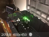
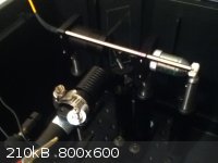
(4) Instead of using a beam-splitter made from a microscope slide, I simply shot the laser beam at a 90 degree angle from the spectrometer collection
tube. (The picture below is misleading because it shows my spectrometer in a backscattering configuration).
(5) For an enclosure, I simply chucked the apparatus into a plastic toolbox from Home Depot. I think this may partly account for the interfering
florescence discussed below, but it seemed to work in a pinch.
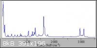
I tested the assembled “ghetto raman spectrometer” on a tablet of CVS aspirin, using three seconds of integration time for each scan, and the
average of 200 scans. I then imported the data into R, cut off everything below 540 nm, and plotted the result (please ignore the axis labels, as
they're inaccurate). Although the resulting spectra has some artifacts, <i>see</i> attached PDF – possibly due to fluorescence or the
filler or coating in the tablet? – if you squint and use some imagination, it has the same dominant peaks as the spectra captured by a professional
instrument (<i>see</i> Horiba Spectra).
Anyway, this is very much a work in progress -- I'm a beginner at spectroscopy and am slowly learning the basics – and I welcome all comments on how
to improve the setup. I plan to build a beam-splitter and compare the results.
Attachment: Aspirin GKau Raman Spectra.pdf (15kB)
This file has been downloaded 2136 times
[Edited on 19-2-2013 by radagast]
[Edited on 19-2-2013 by radagast]
|
|
|
watson.fawkes
International Hazard
Posts: 2793
Registered: 16-8-2008
Member Is Offline
Mood: No Mood
|
|
Good call. That thread was lots of talk and little action. This is a much better start.
Perhaps the best part of this design for most people is that all the electronics for the spectrometer came as a single unit, prepackaged. Not having
to work out CCD electronics certainly removes a major component of skill required to build one. Quote: Originally posted by radagast  | (3) I substituted an inexpensive ~$50 edge filter for the $500 notch filter used by Mohr et al.
[...]
(5) For an enclosure, I simply chucked the apparatus into a plastic toolbox from Home Depot. I think this may partly account for the interfering
florescence discussed below, but it seemed to work in a pinch. |
The notch filter acts as a monochromator. The
same effect can be accomplished with a prism and a slit, but it takes more distance between prism and slit to accomplish the same thing. The filters
are far more compact, something certainly worth paying for in a professional context, but perhaps something the amateur could live with and save
money. The "slit" only needs to be single-sided to mimic the filter behavior of the edge filter. It can be easily built by stacking together a few
razor blades; the shallow grind angle makes an effective beam trap with little backscatter. I mention this because while you found a cheap filter on
eBay, they might not always be available to others.
As for the enclosure, I'd guess that backscatter from the "fourth" ray off the mirror might be your dominant source of the spurious signal you
mentioned. Putting a mirror pointed at the ceiling should give you a quick indication if this is so, or a piece of black cloth, or whatever. If indeed
that's the case, you could put a beam trap there (again, constructed of stacked blades) to remove it.
One question. You didn't mention what kind of optical table you used, nor the mounts on it.
And a request. I have found it quite useful for other people's projects to see a full bill of materials and prices paid for them. Since there's always
some luck in finding inexpensive replacements for otherwise-commercial components, it's useful to see a complete bill, as a way of estimating one's
own budget and effort required to save cash.
|
|
|
radagast
Hazard to Self
Posts: 79
Registered: 28-6-2012
Location: NYC
Member Is Offline
Mood: No Mood
|
|
Thanks for the very helpful comments, Watson. To clarify re: your advice on the backscatter from the "fourth" ray off the mirror, are you referring
to possible reflection from the silver plastic cover when the enclosure is closed during the scanning?
Building a monochromator out of a prism and razor blades is intriguing, and something I'd like to pursue after I get everything working.
To build the infrastructure of the spectrometer, I used a used 8"x8" Thorlab breadboard, and ordered optical posts and post-holders from Thorlabs.
I've attached a very rough draft spreadsheet of the parts required to build this spectrometer, in three configurations:
(1) a "barebones" 90 degree configuration, including the requisite lens tubes, screws, and filters (which I'd consider too much trouble to machine),
but excluding the breadboard, optical posts, etc. which could be made from wood -- c.a. ~$500 USD
(2) a standard 90 degree configuration, which includes the Thorlabs breadboard, optical posts, etc. -- c.a. ~$800 USD
(3) a standard beam-splitter configuration, which includes the Thorlabs breadboard, optical posts, etc. -- c.a. ~$1000 USD
This list isn't 100% accurate, since I've assembled it partly from memory, but I think those prices should be in the right ballpark. It assumes that
one has a Windows XP computer with a serial cable, and that you buy all the components new.
EDIT: I've adjusted the baseline a bit using the "baseline" package in R. Also, the price estimates above are too high by $50; the DIY spectrometer
from Science Surplus was actually $200, not $250.
Attachment: Raman Parts List v.1.pdf (116kB)
This file has been downloaded 3245 times
[Edited on 20-2-2013 by radagast]
|
|
|
radagast
Hazard to Self
Posts: 79
Registered: 28-6-2012
Location: NYC
Member Is Offline
Mood: No Mood
|
|
A word of caution to anyone using a direct D.C. power supply to power the 5 mW green "laser pointer" like the one I listed above: I'd bet my life
that once you connect the D.C. power supply to the laser, the laser emits substantially more power than 5 mW at 532 nm (and possibly at
higher IR modes, too).
Frankly, I had my doubts that the laser pointer only emitted 5 mW at 532 nm even with the supplied lithium battery, but connecting it to a
wall-powered power supply really unleashes the beast within. The green reflection from irradiating a white aspirin tablet is so bright that it's
uncomfortable to view from even 10 feet away in a darkened atmosphere.
532 nm protective glasses (preferably with IR blocking as well) are required for this type of project.
|
|
|
radagast
Hazard to Self
Posts: 79
Registered: 28-6-2012
Location: NYC
Member Is Offline
Mood: No Mood
|
|
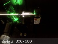
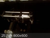
Backscattering Configuration
A quick Saturday-evening update before I begin drinking . . .
I've found that when using the 90 degree configuration to measure solid samples, the precise location of the laser beam on the sample can affect the
intensity of the raman shift. I got some better spectra after my Thorlabs OG10 safety glasses arrived, because the glasses permitted me to aim the
laser better.
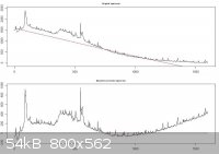
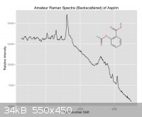
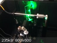
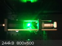
I got substantially better results, however, when I switched to the back-scattering configuration (as designed and described by Mohr et. al). The
back-scattering configuration is simply a beam-splitter constructed from a shard of mirror glued to a microscope slide, which reflects the laser light
through an Amscope microscope objective. The objective both focuses the laser light on the sample, and captures the backscattered raman radiation
back through the microscope slide where it's collected, filtered, and processed.
This configuration captured raman spectra that were more intense than the previously-captured spectra by several magnitudes, resulting in a superior
signal-to-noise ratio. Below, I've attached a sample spectra generated by the backscattering configuration, as well as a few pictures of the setup.
EDIT: Once (if?) I ever get a stable baseline without resorting to numerical methods, I'd really like to try to pair the raman spec with TLC to
identify different eluting compounds.
Attachment: Aspirin_Backscattered_Raman Spectra (GKau).pdf (12kB)
This file has been downloaded 1271 times
[Edited on 24-2-2013 by radagast]
|
|
|
IrC
International Hazard
Posts: 2710
Registered: 7-3-2005
Location: Eureka
Member Is Offline
Mood: Discovering
|
|
Try more like 20 to 50 mw. I have a couple of those. 5 mw is quoted to get past customs.
I like this deal better:
http://www.ebay.com/itm/261089893420?ssPageName=STRK:MEWNX:I...
If you look at the fine print you see "Output power:< 2mw". It is actually 200 mw or very close but ebay would kick it off and customs grab
them thus the lie. It is more of a code they use to get these sold and delivered. Easy to figure out when you read "Burning: can burn the black
matches within 10cm after adjustable focus". Mine lights red non strike anywhere matches easily and cuts out patterns in trash bag plastic quite
easily. As you can guess it is not a 2 mw laser. Neither is the one you have a 5 mw. Be sure to add a note you are in the U.S. and it will come with
the sleeve and 18650 battery. However do not run it above 3.7 volts if you are going to use a supply. No reason to damage it and as I stated it will
light matches at 3.7 volts so the power is plenty for your project.
At $33 including the battery, sleeve, laser, keylock, and safety glasses I think this is a great deal. Also includes a screw on front assembly which
projects the beam like a disco ball with dozens of points. I just use it to keep the lens covered and dust free when I am not using it.
"Science is the belief in the ignorance of the experts" Richard Feynman
|
|
|
radagast
Hazard to Self
Posts: 79
Registered: 28-6-2012
Location: NYC
Member Is Offline
Mood: No Mood
|
|
Thanks for the heads-up, IrC. When I saw the beam of my laser glittering brightly, I began to get the clue that it was not in fact < 5 mW. And,
when the beam felt like a burning ember after adjusting the focus a bit and shining it on my hand, that's when I started sprinting for the safety
glasses. In fairness to the manufacturer, that happened after I supplied power from a D.C. adapter -- but that just makes me think that the laser
pointer contains an over-spec'ed (or lacks) current regulation.
I was simultaneously so angered and pleased that I immediately had my eyes checked for retinal damage, and then ordered another one.
I'd find a 200 mW laser "pointer" terrifying, but I'll probably order it anyway to try it out. The problem is that the current less-powerful laser is
already strong enough to partly overwhelm the edge filter, and I have a feeling that a 200 mW laser would be too much without adding a stronger
filter. In addition, the seller says that the laser should not be operated for longer than 30 seconds due to heat buildup (another clue that this
isn't your average "2 mW" laser . . .). This is a problem, because I generally collect hundreds of spectra and average them, with each spectra taking
anywhere from 50 milliseconds to 10 seconds each. But at $30 bucks or so, it's basically the cost of two NYC vodkas, so why not . . .
I have to LOL at the idea of using a 200 mW laser as a pointer at a presentation at my job while trying a case. Really gives a literal dimension to
the phrase "blind justice" . . .
|
|
|
IrC
International Hazard
Posts: 2710
Registered: 7-3-2005
Location: Eureka
Member Is Offline
Mood: Discovering
|
|
Just be careful one good hit even from a piece of the power reflected, that eye is gone for life. Just had a mini ice storm 2 days ago and shining up
to low clouds with some de-focusing it lit a big patch of cloud very brightly. First pointer I have seen do that. With tighter focus you can see it on
very high clouds, one of the reasons I like the green. My 300 mw blues burn things even better but just not visible enough to see in a cloud. Running
on the 18650 I have kept it lit a few minutes and while getting warm I don't think it cut the life down very much. Would be a different story on a
power supply.
I do not need to say don't point it up when any aircraft are anywhere around. This laser is most definitely not a toy, thus the set of keys to protect
kids when your not around.
I should add this is a very good thread, should probably be in technochemistry. Also I wish you would add some in depth detail in all aspects of your
project here these are the subjects which make me want to go start building things. Would also be nice if someone added some good detail on the
devices they are using to detect trace chemicals on things from a hundred or more feet away. Very interesting topic.
[Edited on 2-24-2013 by IrC]
"Science is the belief in the ignorance of the experts" Richard Feynman
|
|
|
watson.fawkes
International Hazard
Posts: 2793
Registered: 16-8-2008
Member Is Offline
Mood: No Mood
|
|
| Quote: Originally posted by radagast | | The problem is that the current less-powerful laser is already strong enough to partly overwhelm the edge filter, and I have a feeling that a 200 mW
laser would be too much without adding a stronger filter. |
Yet on the other hand, the higher power makes for
more non-linearity in the target, leading to better signal. What to do?
There are two ways of lowering power of a laser diode: lower the current or lower the duty cycle. The first is obvious. The second, though, opens the
possibility of turning off the spectrometer sensor while the power is on. This would avoid flooding the CCD with immediately-reflected light. This
technique goes by the name "time-resolved" spectroscopy. It's not off-the-shelf, as your current system is, since it requires a time base connection
between a pulsed supply and the spectrometer, not to mention that a suitable pulsed supply isn't COTS (commercial off the shelf) either (not to my
knowledge). On the other hand, it might be possible to modify the spectrometer if its CCD chip has the right pin, one that, say, would prevent charge
accumulation which the pin was held active. The pulsed supply itself is pretty easy; it's a variable duty-cycle oscillator with a MOSFET output to
switch power to the diode.
Here's a related paper, pulled at random:
A Low Cost Time-Resolved Raman Spectroscopic Sensing System Enabling Fluorescence Rejection
|
|
|
unionised
International Hazard
Posts: 5102
Registered: 1-11-2003
Location: UK
Member Is Offline
Mood: No Mood
|
|
I think I may be able to beat you all for the ultimate cheapskate Raman system.
In a fully darkened room, the light scattered from a green laser pointer (probably about 1mW) by a strong solution of sodium chromate is visible
through a bandpass filter that blocks the green but lets the yellow light through.
So I have seen a Raman spectrum- albeit that there's no real wavelength discrimination in these circumstances.
I'm thinking of ways to improve this. I think the first thing I need is to take the laser out of a pointer and fit it in a box that will not roll off
the table and wich doesn't need you to hold the button down with sticky tape.
I forget how much the filter cost me- it was on ebay It's not very narrow band, but it doesn't need to be since it's centred on yellow light; it
blocks the green completely.
|
|
|
radagast
Hazard to Self
Posts: 79
Registered: 28-6-2012
Location: NYC
Member Is Offline
Mood: No Mood
|
|
I'm still trying to find out what's causing the elevated baseline in the back-scattering configuration. I'm thinking about installing a beam dump (as
Watson Fawkes suggested) to absorb excess laser light behind the beam splitter, or putting the apparatus in a different enclosure. In the meantime,
here's an interesting youtube video by "toc1955" who used a raw CCD to capture raman spectra from a blue laser. Instead of using a filter to exclude
the laser wavelength, he just covered the area of the laser corresponding to the laser wavelength with black cardboard:
http://www.youtube.com/watch?v=-lVMYa25jtU
@IrC:
I'd be happy to post additional details once I get clean spectra, with a complete write-up on calibrating the spectrometer, etc. One of my
motivations for pursuing laser spectroscopy is the thought that, over time, enough people will build these to create a growing library of raman
spectra, which would be tremendously useful in confirming product identity.
Your warnings on wearing glasses are well-taken, especially when aligning optics. (For instance, I took a indirect hit in my left eye from the laser
while aligning the beam-splitter. Because I was wearing safety glasses, I only saw a faint flash of green instead of sustaining any damage). Re:
long-distance raman spectroscopy, I had actually came across an article describing the basics and will post it once I find the link.
@Watson Fawkes:
That's a fascinating article. Frankly, circuit design (and EE projects in general) are my "blind spot" and the last time I worked with MOSFETs was
almost 15 years ago, when seeking to build a tesla coil as a kid. Would love to pursue this further when (if?) I ever gain knowledge sufficient to
create those timing circuits.
@Unionised:
Nice work. I actually experimented with using my 532 nm protective glasses as raman filters. It worked to the extent that the most dominant raman
signals appeared on the spectra, but the raman signals were generally quite weak. I don't think those glasses were spec'd to let in a percentage of
non-532 nm light.
With respect to your laser pointer, I'd recommend using a pipe clamp to hold down the button. (See pictures in previous posts). You can then use a
vise to hold the laser steady.
In order to see discriminate between wavelengths, you could use a "real" spectrometer (as I did), or you can create one out of diffraction grating (a
DVD would probably do the job), a high-resolution digital camera, and a few mirrors. The diffraction grating will resolve the raman light into
different lines, which can then be photographed by a calibrated camera. See, e.g. "A simple spectrophotometer using common materials and a digital
camera", J. Physics Education, 46(3) (claiming .5 nm resolution over the 415-660 nm spectrum using similar materials). You can then use software to
convert the spectral image to a wavelength/intensity spectra. (I would have tried something similar, but getting consistent raman spectra is already
difficult so I figured I focus on getting the basics right first).
[Edited on 25-2-2013 by radagast]
|
|
|
radagast
Hazard to Self
Posts: 79
Registered: 28-6-2012
Location: NYC
Member Is Offline
Mood: No Mood
|
|
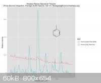
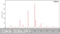
Toluene Spectra, and Sample Vial Test
One of the really neat things about raman spectroscopy is that there's virtually no sample preparation. I've heard claims that you can test samples
simply by shooting the laser at a reagent bottle. I found this was true, to the extent that the bottle is made of clear glass. (YMMV -- I'm sure a
different configuration would fare better with other kinds of glass).
Today, I received a tiny amber bottle of toluene, which was ideal for testing because it's a strong raman scatterer. I tested the toluene straight
out of the USPS box without opening the amber bottle. Glass is a very weak raman scatterer, but I found that it blocked enough raman-shifted light to
greatly weaken the signal.
After opening the bottle of toluene, I poured it in a clear glass vial, and obtained a much stronger signal. I've plotted the amber vs. glass spectra
using the terrific ggplot2 R package by Hadley Wickham. I've also attached a high-resolution professional spectra of toluene. As you can see, the
"ghetto raman spectrometer" did not fully resolve the ~1000 cm-1 doublet in the glass vial, but did so when scanning the amber bottle. Perhaps the
dominant peak at 1000 cm-1 is obscuring its sister peak. The spectra contain other small artifact peaks, but there is otherwise a fairly good match.
Attachment: Amateur Toluene Raman Spectra (GKau).pdf (11kB)
This file has been downloaded 1420 times
[Edited on 26-2-2013 by radagast]
|
|
|
NHZ
Harmless
Posts: 22
Registered: 9-8-2011
Member Is Offline
Mood: No Mood
|
|
A quick note on the laser used. Low cost 532's usually do not come with an IR filter. This allows 3
wavelengths to pass. Given the working distance of your setup, you get a ton of IR 808nm & 1064nm
spewing out at aperture.
Regarding ebay, there are China based sellers that list 405nm pointers as 5mW and have been tested
up to 80mW. They do this to circumvent customs, and keep the listing from being pulled. The insanity
to this is that common people buy these near UV lasers to play with pets and im sure even some
allow their kids to play around with them.
Always be very cautious of anything listed as 5mW and made in China. Sellers who list as 1mW
do this as some countries restrict over 1mW. Very distressing to say the least.
If you are interested, I build my own DPSS modules from the driver through to the mounting and
alignment of the pump medium. I can set desired outputs tested on a calibrated power meter.
My 532 modules are also IR filtered and include power supply. I also work with 473nm
I have some videos for reference here > https://www.youtube.com/user/TunedCavityLasers
A lot of what I do is high power stuff, but also make reliable low power as well.
[Edited on 26-2-2013 by NHZ]
|
|
|
IrC
International Hazard
Posts: 2710
Registered: 7-3-2005
Location: Eureka
Member Is Offline
Mood: Discovering
|
|
Would one of these filters work in your project radagast? Until Friday they are having a 46 percent discount on everything they carry, mostly optical
items.
http://www.surplusshed.com/pages/item/l10079.html
http://www.surplusshed.com/pages/item/l10076.html
http://www.surplusshed.com/
"Science is the belief in the ignorance of the experts" Richard Feynman
|
|
|
watson.fawkes
International Hazard
Posts: 2793
Registered: 16-8-2008
Member Is Offline
Mood: No Mood
|
|
| Quote: Originally posted by IrC | | Until Friday they are having a 46 percent discount on everything they carry, mostly optical items. |
I
couldn't find this sale on their web site anywhere. Turns out that's because it's not there. It's on their Twitter feed: https://twitter.com/SurplusShed.
|
|
|
IrC
International Hazard
Posts: 2710
Registered: 7-3-2005
Location: Eureka
Member Is Offline
Mood: Discovering
|
|
If you have been buying from them a long time and are on the mailing list they send you a coupon code in the email. Never thought about that but your
right, good you looked at their TF. While your still around do you have an opinion on the two filters I listed as relates to this thread? I have never
really delved into this subject before so I am unsure until I study much more just how to choose a filter for the project. Since that would take me
more than a few days and the sale ends soon I thought getting advice makes sense.
"Science is the belief in the ignorance of the experts" Richard Feynman
|
|
|
radagast
Hazard to Self
Posts: 79
Registered: 28-6-2012
Location: NYC
Member Is Offline
Mood: No Mood
|
|
@IrC:
Thanks for the link! Some great stuff for sale there. Frankly, I'm not sure what they are. I'll defer to WF and other posters more knowledgable
about optics, but the filter resembles a "dichroic mirror/beamsplitter" described by Thorlabs:
| Quote: | A dichroic mirror/beamsplitter functions as a 50:50 beamsplitter at its design wavelength, known as the cutoff wavelength. A longpass dichroic mirror
is highly reflective below the cutoff wavelength and highly transmissive above it, while a shortpass dichroic mirror is highly transmissive below the
cutoff wavelength and highly reflective above it.
Thorlabs' Dichroic Mirrors/Beamsplitters are offered in eleven different cutoff wavelengths ranging from 425 - 1800 nm, and they provide >90%
average transmission and >90% average reflection over their specified bands (see the graphs below). They are designed for use at a 45° angle of
incidence and are available in sizes of Ø1/2", Ø1", Ø2", and 25 mm x 36 mm. Please refer to the table to the right to choose an appropriate filter
for your application, and see below for representative transmission and reflection plots.
Dichroic filters feature a dichroic coating on one surface and an antireflection coating on the opposing surface. On round optics, an engraved arrow
points toward the surface with the AR coating; on rectangular optics, the side with the engraving has the dichroic coating.
Applications
Dichroic mirrors/beamsplitters can be used to combine a beam that has a wavelength (or wavelength range) shorter than the design wavelength with a
beam that has a wavelength (or wavelength range) longer than the design wavelength while minimizing intensity losses. Alternatively, spatially
overlapping beams of different colors can be split with a single optic. This feature is commonly used in fluorescence microscopy to prevent light of
the excitation wavelength from reaching the imaging detector. Please see the Applications tab for schematics of example experimental geometries.
|
http://www.thorlabs.com/newgrouppage9.cfm?objectgroup_id=331...
SurplusShed doesn't specify whether the filter is longpass or shortpass, and I can't really tell by the color. The filter I use (an edge filter that
cuts off a high % of light under 540 nm) is dark red/orange, and this one is dark red, but I'm not sure that means too much. Assuming it is, though,
I suppose you could use it as a dual beamsplitter/filter, and substitute it for both the microscope slide and the filter in my setup. The problem is
that it'll still let through a lot of 532 nm light, since under our assumptions, it only cuts off at 531.6 nm. That means that the laser light will
still likely drown out the raman signals. On the other hand, if this is a shortpass filter, it will block everything above 531.6 nm, including the
stokes raman shifts that we need.
I might grab a few just to test it out, though. If it pans out, I'd be happy to send one of them your way. Generally, what you're looking for is a
filter that will cut off around as much light < 540 nm, while letting through virtually everything > 540 nm. In a pinch, you can use an OG550
filter (basically, a piece of orange glass), but these cut off around ~580 nm (IIRC) so you lose the rich structural information between ~150 to ~1000
cm-1.
I actually have five of these OG550 filters which I'll never use, since I ordered the wrong size (they're tiny, maybe 1 cm diameter?) so if you want
one, just PM me your address and I'll send one to you.
@NHZ
Frankly, I'm surprised that these laser companies haven't been litigated into the ground. I would launch a class-action suit myself but-for the fact
that I love their product . . .
Do you have any recommendations for (1) a laser power meter; and (2) a high-resolution spectrometer for testing laser modes? With respect to the
latter point, I'm thinking of getting one of those blue single-mode diodes that are typically used in a projector.
[Edited on 27-2-2013 by radagast]
[Edited on 27-2-2013 by radagast]
|
|
|
watson.fawkes
International Hazard
Posts: 2793
Registered: 16-8-2008
Member Is Offline
Mood: No Mood
|
|
The filter description (for one of them) is
"MOUNTED 15.5MM SQUARE INTERFERENCE FILTER FOR 531.6NM". The magic search term is "interference filter". The page on Wikipedia is so-so. Much better is the page on HyperPhysics. You need to know some optics, in any case, but nothing more that first-year college physics to grasp the basics. If you look
at both photos, front and back, you'll note that they show different colors, which is typical of any interference device.
The real question, though, is what kind of interference filter is it? Given the mounting and the small window, I'd guess that it's for mounting
perpendicular to a beam, not originally in the middle of some more complex optical train. It might have been a laser line filter, used to pick out a
narrower frequency range than the ordinary output is. I don't know enough about that class of materials to say anything about what the beam centered
at 532 nm looks like in frequency space, but it's fairly safe to say that it will be narrower if you put in a laser line filter. It's also safe to say
that those cheap high-power lasers are built for output power, not monochromaticity. If (a big if) it's actually a narrow pass filter, then you'd put
it right after the laser emitter, before the rest of the optical train. It might cut down a lot of the spurious noise in system as a whole.
|
|
|
watson.fawkes
International Hazard
Posts: 2793
Registered: 16-8-2008
Member Is Offline
Mood: No Mood
|
|
I got curious about why there should be commercial paired filters near 532 nm. For the easy-to-see version, see the article Neodymium-doped Gain Media. The 4F3/2 level for the Nd ion is split into a doublet (R1-R2) by the Stark effect that arises from electric fields within the crystal lattice. The 4I11/2 level is split, as it turns
out, into a sextuplet (Y1-Y6). I found more complete data in this paper (full title formatted, just for you all): Stark components of lower-lying manifolds and emission cross-sections of intermanifold and inter-stark transitions of Nd3+(4f3)
in polycrystalline ceramic garnet Y3Al5O12. Figure 2 of that paper has the intensity data for the
4F3/2 --> 4I11/2 transition, the strongest two of which are both near 1064 nm,
which after frequency doubling gives the 532 nm green. I'd have to guess these filters were designed to separate this line pair.
|
|
|
radagast
Hazard to Self
Posts: 79
Registered: 28-6-2012
Location: NYC
Member Is Offline
Mood: No Mood
|
|
@Watson
You are a fountain of knowledge, sir. I was wondering about the strange range of the filter too, but I can't claim to have ever even heard of the
Stark effect.
Just a random collection of updates --
(1) The DIY spectrometers are back up on Ebay again. See, e.g. http://www.ebay.com/itm/Compact-Fiber-Coupled-CCD-Spectromet...
(2) I accidentally left the laser on for about 24 hours. It was warm to the touch, but seemed to be perfectly fine. So, I'm hopeful that this
configuration will be relatively stable.
(3) There's a terrific tutorial on how to make your own optical breadboard at youtube by "plenum88". See, e.g. http://www.youtube.com/watch?v=sr22VxNpk8U
(4) The spectra I've posted are definitely not optimized, because the spectrometer is not highly calibrated and the laser probably has fatter
spectral width than we'd like. By way of example, a dedicated laser fanatic took the same spectrometer, shot a 532 nm laser into it, and took
spectra where the base of the laser spectra spanned 530 to 534 nm. See http://redlum.xohp.pagesperso-orange.fr/electronics/spectrom...
By comparison, a similar test on my spectrometer yields a substantially broader base (~528 to ~536 nm).
[Edited on 1-3-2013 by radagast]
|
|
|
watson.fawkes
International Hazard
Posts: 2793
Registered: 16-8-2008
Member Is Offline
Mood: No Mood
|
|
I was curious as to whether the spectrometer used in this project could be hacked to do any time-resolved functions. The short answer is no. Its CCD
is a Sony ILX511, a 2048 pixel linear B/W sensor. It's big brother is the Sony ILX526A, a 3000 pixel linear B/W sensor. The ILX526A has an electronic
shutter function; the ILX511 does not. See this new product announcement for a summary. This announcement isn't dated, but a little digging with the Wayback Machine first shows this page in December 2003 referencing the ILX526A.
From what I can tell, the most recent linear CCD from Sony with shutter is the ILX718K, a 5363 pixel linear RGB sensor.
|
|
|
radagast
Hazard to Self
Posts: 79
Registered: 28-6-2012
Location: NYC
Member Is Offline
Mood: No Mood
|
|
@Watson
The Sony ILX511 is also the chip used in the Ocean Optics 2000 series, so at least in terms of CCD capability, these B&WTek/Science Surplus seem
to offer similar hardware as substantially more expensive spectrometers.
Do you have any thoughts on how difficult it would be for someone without electrical-engineering experience to pair a CCD with a circuit driven by
commands from a computer? I think it'd be neat to see if I could replicate what's going on inside the little blue spectrometer box on an optical
breadboard, and learn more about Czerny-Turner designs. I'd also be interested in developing a command-line interface to the CCD so that I could tell
it to record spectra using a range of integration values to find the optimum integration time.
Plus, the upgraded CCDs you mentioned could be scavenged from scanners, and are readily available . . .
[Edited on 1-3-2013 by radagast]
|
|
|
watson.fawkes
International Hazard
Posts: 2793
Registered: 16-8-2008
Member Is Offline
Mood: No Mood
|
|
| Quote: Originally posted by radagast | The Sony ILX511 is also the chip used in the Ocean Optics 2000 series, so at least in terms of CCD capability, these B&WTek/Science Surplus seem
to offer similar hardware as substantially more expensive spectrometers.
Do you have any thoughts on how difficult it would be for someone without electrical-engineering experience to pair a CCD with a circuit driven by
commands from a computer? |
For reference, I've attached a copy of the data sheet for the ILX511. In the block
diagram on page two, you'll notice that the block next to pin 1, VOUT, is labelled in part "S/H Circuit". That stands for "Sample and
Hold", and pin 1 is an analog output. In order to get data, it needs to be fed into an A/D converter. So the short answer to the question is no, you
can't drive the chip directly from a computer.
The longer answer is that it doesn't take a huge amount of electronics knowledge to interface the chip with a microcontroller and to build something
that would interface nicely with a host computer. The saturation voltage is listed at 800 mV and the dark voltage is listed at 3 - 6 mV with
excursions twice that. There might be some issues with matching these voltages to the those of a built-in microcontroller. These could be solved with
a level shifter, a simple op-amp circuit. The dynamic range of this chip is listed at only 267 (= 800 mV / 3 mV ), and if you take the denominator as
the dark current variance, it means there's not much more that 8 bits of good data coming out of the chip in the first place. So if you were going to
do this with an Arduino, which uses an AVR chip with 10-bit A/D converters, you'll be fine. The max sampling rate of the chip is 2 MHz and the Arduino
has a 16 MHz clock rate, so there's 8 clock cycles of instruction available for your central sampling rate (or twice that if you drop it down by a
factor of 2), which means you need to hand code it in assembler. All in all, not a beginner's project, but a decent medium-difficulty one.
This analysis is more-or-less generic for all these sensor chips. They've all need an external A/D to function, and there's always a sampling loop in
the microcontroller code. I did a little hunting for other chips yesterday, and they all seem to have the same style of interface, even those from
other vendors. The other change, and this is more significant, is that CCD seems to have passed out of service entirely for new linear sensor designs,
having been replaced with CMOS sensors.
A note on chip availability. The ILX526A seems to be available as NOS (new old-stock) for around $20. If anybody's going to go to the effort to build
a linear interface board, I'd highly recommend using a sensor with shutter control. Given the amount of time invested in such a project, it seems
silly not to have the option of using it later.
Lastly. If you want to experiment with spectrometer optics, the very easiest way of getting a linear sensor like the one you're already using is to
buy a second box like the one you've got and extract its sensor board for your own use.
Attachment: ILX511 2048-pixel CCD Linear Image Sensor B-W, Sony.pdf (129kB)
This file has been downloaded 1271 times
|
|
|
radagast
Hazard to Self
Posts: 79
Registered: 28-6-2012
Location: NYC
Member Is Offline
Mood: No Mood
|
|
@Watson
Thanks for the detailed advice, Watson -- that's very helpful! It'll probably take me at least several months to get a prototype working, but I've
been eager to learn some basic circuit-building so this will be a great way to do that, and hopefully work my way toward using a ILX526A chip. Re:
the easiest way of getting a linear sensor, I'll snag another one of those DIY Science Surplus / B&WTek spectrometers, take it apart, and replace
the built-in breadboard with a custom setup. Even if it doesn't work, I could always put the circuit and CCD back into the built-in breadboard, and
calibrate that spectrometer for use with a laser of a different length.
@all
(1) I built a few more beam-splitters to determine the effect of the mirror size on the spectra, and found that mirrors can introduce artifact peaks.
For instance, one of the annoying artifact peaks at around ~2600 cm-1 in the aspirin spectra disappeared after I installed a new
beam-splitter.
(2) The DIY Science Surplus / B&WTek spectrometer comes with a help file containing codes for communicating with the spectrometer, which opens up
the possibility of writing your own serial interface to it. I'm going to poke around and see whether I can write a simple Python program to control
the spectrometer.
[Edited on 3-3-2013 by radagast]
|
|
|
watson.fawkes
International Hazard
Posts: 2793
Registered: 16-8-2008
Member Is Offline
Mood: No Mood
|
|
I spent some time over the weekend looking into linear image sensors. The main application seems to be document scanning, so a number of these chip
are "x 3" with RGB outputs. There seems to have been much more competition a decade ago for these. What seems to have happened is that the business
has gone primarily wholesale, with large sales to major manufacturers.
Here's the upshot: TSL1412S - Linear Sensor Array with Hold. Available through ordinary channels like Digi-Key and Mouser. Cost is USD 40 - 45. This is the chip I'd
use in any new design. Widely and easily available, has a shutter, adequate linear density, good dynamic range.
ams (formerly Taos). The maker of the chip referenced above.
Sony. I couldn't find a page on any Sony site, but here's one from Framos Imaging for the ILX* series. I'm not sure Sony is still active in this product category, but there still seems to be stock floating around.
Toshiba. Lists products, but I didn't find distributors.
One thing I learned that I was a bit surprised to learn is that a few of the vendors don't sell through to retail channels; you have to call them
to know anything at all about buying from them. These, not so fortunately for the amateur, also seem to be the most scientifically oriented ones. I
didn't talk to any of them. I've listed them for completeness, but I wouldn't use them in any design for amateurs, because of the hassle of getting
them as well as the uncertainty about availability in the first place. Also, I'm not sure that Sony and Toshiba shouldn't be on this list.No longer producing product. Best I can tell, they've left the business. Plenty of data sheets for previous products out there, and some NOS (new
old-stock) inventory.Renesas (formerly NEC Electronics).
Seiko Instruments, Inc. (abbreviated SII)
|
|
|
| Pages:
1
2
3
..
10 |
|


