| Pages:
1
2
3
4
..
10 |
IrC
International Hazard

Posts: 2710
Registered: 7-3-2005
Location: Eureka
Member Is Offline
Mood: Discovering
|
|
radagast "I actually have five of these OG550 filters which I'll never use, since I ordered the wrong size (they're tiny,
maybe 1 cm diameter?) so if you want one, just PM me your address and I'll send one to you."
Thanks I just received it today in the mail. Have a bit of studying and building to do. I am thinking about looking into Watsons flatbed scanner
sensor idea. Now on to searching ebay for a good new or used CCD, one I can find in depth data on before
I buy it. Have an Arduino 2560 Mega which might be a good project to work on.
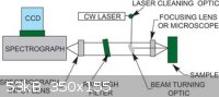
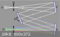
After doing some searching I find a lot of the information to be quite vague. Example in the image. Is the Rayleigh filter set at a specific angle
such as a Brewster angle? Do you want the beam hitting the target sample as tightly focused as possible? Would blue work better than green? I know
different filters but I am curious. Also if we have a liquid sample in a Curvette, would the point of beam focus be in the center of the Curvette?
Most of the pages I have looked at are geared towards describing the setup in broad, general terms. Do not really find a specific example with
everything shown with precision, leaving many questions.
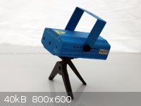
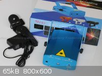
http://www.ebay.com/itm/Mini-Projector-DJ-Disco-stage-light-...
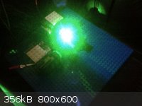
I hacked one of these. Two lasers in nice holders, one shining through a flat square splitter at 90 degrees, other at Brewster angle, resulting in a
single beam of both. Circuit board regulates each and has a fet condenser mike for activation of both lasers from room audio. Floating differential
input but an audio transformer is easy isolation (you cannot reference either side of the mike to ground or it kills the laser supply). This could be
used to switch the beam assuming you remove one laser for the project, say keeping the green for example. The green is around 80 mw and the red is
closer to 120 mw. At $28.99 free shipping it is a great source for lasers of decent power plus the other components. Not to mention it is a neat light
show even if somewhat boring after a while. Instructions say do not leave on past a couple hours. I left it on for two weeks nonstop with no
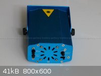
observable reduction in either laser, the unit has a very efficient yet quiet fan. You can see the fan output in the third image below. Runs on 12
volts and comes with everything in the pictures. A goldmine of hackable parts for this project and very easy to disassemble, nicely built. I am sure
the motorized grating assembly could be used for something else and you can use the beamsplitter as in the first image above.
[Edited on 3-6-2013 by IrC]
"Science is the belief in the ignorance of the experts" Richard Feynman
|
|
|
smaerd
International Hazard
Posts: 1262
Registered: 23-1-2010
Member Is Offline
Mood: hmm...
|
|
Incredible work. Gets me thinking about making an IR spec. Wish I had anything to add on hehehe.
|
|
|
IrC
International Hazard
Posts: 2710
Registered: 7-3-2005
Location: Eureka
Member Is Offline
Mood: Discovering
|
|
I should add the 'beam turning optic' in the top pic is what I was referencing concerning using the really high quality splitter that comes in the
laser light show. The green laser will shine at 90 degrees to the splitter face, and the signal will go through it at roughly the Brewster angle. Does
anyone see any reason this will not work?
"Science is the belief in the ignorance of the experts" Richard Feynman
|
|
|
bfesser
Resident Wikipedian
Posts: 2114
Registered: 29-1-2008
Member Is Offline
Mood: No Mood
|
|
Every time I see the title of this thread, I read it as 'Cheap, Low-Resolution, Ramen Spectroscopy':

[Edited on 3/7/13 by bfesser]
Fixed broken HTML -Texium
[Edited on 11-19-2018 by Texium (zts16)]
|
|
|
radagast
Hazard to Self
Posts: 79
Registered: 28-6-2012
Location: NYC
Member Is Offline
Mood: No Mood
|
|
@all
Not directly related to raman, but once you get into lasers, you might as well go all the way into laser-induced atomic emission spectroscopy. Not
the most useful technique for organic chem analysis, but very impressive:
http://www.viewsfromscience.com/documents/webpages/methods_p...
@Watson
As always, thanks for the expert advice -- I'll look further into TSL1412S. I have a feeling that those other suppliers may require ordering in
bulk, but I may give them a dial just to check. In speaking with other scientific suppliers (e.g. Gilson, Shimazu, B&WTek) I've found that their
tech support are often willing to go the extra mile for interested amateurs, so you never know.
@IrC
With respect to the positioning of the laser, the ideal spatial resolution, and the angle of the beam -- those are good questions, and largely
empirical as far as I can tell. I've been tied up with my day job for a while, but I'm hoping that I can test the spectrometer in a bunch of
different configurations this weekend and post the resulting spectra and higher-resolution photos of the my current setup so that other people don't
have to reinvent the wheel. (I dream of high-res raman but my highest res camera is the one that came with my Blackberry . . . go figure).
You can use a blue laser, and the wavenumber shifts should still be the same as those from a green laser. As your excitation wavelength decreases,
the raman signal increases exponentially. However, the tradeoff is that fluorescence also increases, and my view is that flourescence is a much
bigger problem than detecting the faint raman signal. (Hence my interest in Watson's article re: time-resolved spectroscopy).
Thanks for the details on the laser projector . . . looks promising and I'll check it out.
@smaerd
I wish someone would build an IR spec . . . I searched for a DIY IR spec, but it seemed like nobody had done this and published the results. Raman
and IR are complementary techniques, so it would really be something if we could have access to both.
What would be really cool is if there were something like a handheld Heath-kit raman set available that you could put together yourself, which had
software for the iPhone or Android-based phones which would match up to a library of spectra taken by other users . . . I feel like that is what's
needed to gain a critical mass of freely-available raman spectra. Probably a pipe dream, but it'd be great to be able to analyze your tap water with
your phone and a little accessory, or your soil, or whatever you want.
@bfesser
Pretty sure you just won the thread, almost no point in continuing now! By the way, would like to hear your progress on the CCD controller, as we're
working toward similar ideas.
[Edited on 7-3-2013 by radagast]
|
|
|
watson.fawkes
International Hazard
Posts: 2793
Registered: 16-8-2008
Member Is Offline
Mood: No Mood
|
|
Quote: Originally posted by radagast  | | In speaking with other scientific suppliers (e.g. Gilson, Shimazu, B&WTek) I've found that their tech support are often willing to go the extra
mile for interested amateurs, so you never know. |
That is indeed true. On the other hand, one of my reasons
for recommending that chip was that it's appropriate for an open source design, so that the supplier who isn't set up to handle the volume of interest
from less-than-expert amateurs is not swamped by such calls.
|
|
|
IrC
International Hazard
Posts: 2710
Registered: 7-3-2005
Location: Eureka
Member Is Offline
Mood: Discovering
|
|
When you have the time to operate your setup I would be interested in an analysis of the beef noodles, with and without MSG. I never liked the chicken
and their spicy shrimp always burned my guts out so no need to do them.
bfesser one of us has been up for too many hours. I just realized your spectral lineup of noodles.
On the link for Laser-induced breakdown spectroscopy I noticed mention of a very old book, "How to work with the spectroscope", 1878, John Browning. I
looked it up on Archive, they have it. Old but interesting, I D/L'ed the PDF version. Often I find these old texts very informative. Working with
crude technology they built some very high quality instruments. Not to mention often these older books do better jobs of teaching some subjects than
many newer texts.
http://archive.org/details/howtoworkwithspe00browrich
[Edited on 3-7-2013 by IrC]
"Science is the belief in the ignorance of the experts" Richard Feynman
|
|
|
Marvin
National Hazard
Posts: 995
Registered: 13-10-2002
Member Is Offline
Mood: No Mood
|
|
Really cool project. I have some of the bits, I'm playing catchup.
The TSL1412S looks to be CMOS technology and the datasheet indicates it does not integrate well beyond 100ms. Doesn't sound suited to Raman.
The ILX511 is sensitive, 2k CCD and has a low read noise. The Toshiba TCD1304AP is almost a 4k CCD. It is gated, has a better well depth and has a
slightly greater read noise. Both of these are inexpensive and available.
If the B&W based spectrometer 50um slit could be replaced with a 25um slit, this would significantly boost the resolution. Did this come up in
any of your conversations radagast?
|
|
|
radagast
Hazard to Self
Posts: 79
Registered: 28-6-2012
Location: NYC
Member Is Offline
Mood: No Mood
|
|
@Marvin
Thanks, I think it's terrific that you and IrC are working on this project, too! I haven't thought about changing the spectrometer parameters too
much (other than mulling over the CCD stuff and ordering The Art of Electronics so I can get a better handle on circuit basics), because I
have a feeling that the spectrometer I'm using right now actually has decent resolution if used correctly (1 nm or so). The main thing reducing the
quality of the spectra, I believe, is my poor calibration of that spectrometer, and my lack of technique as far as where to shine the laser beam, etc.
-- e.g. what IrC was asking about above.
Reducing the slit is a good idea -- the only issue is that it would reduce the amount of light coming in, and the raman scattering is already so weak.
But once we get the other parameters fixed, it's certainly worth a look.
@all
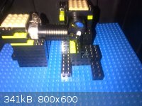
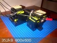
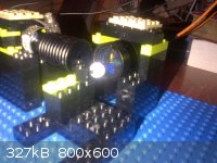
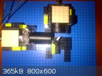
I passed by FAO Schwartz today, and inspiration struck: I thought I might be able to create a Lego 90-degree prototype for those people who might be
interested in this project, but don't want to spend barrels of cash for Thorlabs posts, a breadboard, accessories, etc. (You can pry my Thorlabs
parts out of my cold, dead, hands because I love'em, but they are pretty pricey). Much to my disappointment, all the Lego kits there were custom Lego
sets, and there were no simple Lego bricks there.
Long story short, I raided the Lego store at the Rockefeller center, and after 20 bucks, 15 minutes of shopping, and about 15 minutes of building, I'm
proud to present the LEGO RAMAN SPECTROMETER, which is even shabbier than the first version of the raman spec I built.
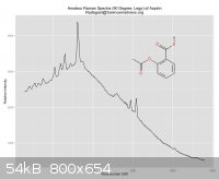
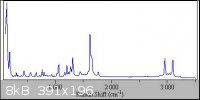
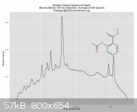
Interestingly, the 90 degree Lego Raman spec took pretty good spectra of aspirin -- in fact, just as good as the backscattering configuration with
Thorlabs parts. After some experimentation, I found that the sample has to be close to the collection filter as possible -- otherwise, the raman
signal will be too weak. I've attached the professional aspirin raman spectra, too, for comparison.
I haven't found an effective way to take liquid spectra at the 90 degree angle yet, but will experiment a little this weekend, as well as finally
taking some pictures with a higher-res camera of the Thorlabs backscattering configuration.
Attachment: GKau (Lego 90 Degree) Aspirin Raman Spectra.pdf (17kB)
This file has been downloaded 868 times
[Edited on 8-3-2013 by radagast]
|
|
|
watson.fawkes
International Hazard
Posts: 2793
Registered: 16-8-2008
Member Is Offline
Mood: No Mood
|
|
| Quote: Originally posted by Marvin | The TSL1412S looks to be CMOS technology and the datasheet indicates it does not integrate well beyond 100ms. Doesn't sound suited to Raman.
The ILX511 is sensitive, 2k CCD and has a low read noise. The Toshiba TCD1304AP is almost a 4k CCD. It is gated, has a better well depth and has a
slightly greater read noise. Both of these are inexpensive and available. |
There are higher-quality chips
available, that's certain. If you don't plan on publishing a design for other amateurs to learn from and build with, use anything you'd like. General
availability is not a concern in such a case. When I was looking, however, the Toshiba and Sony chips were only available in various end-of-life
channels, which include eBay and the various surplus-stock IC vendors; I couldn't find any of the major distributors that were stocking them.
|
|
|
IrC
International Hazard
Posts: 2710
Registered: 7-3-2005
Location: Eureka
Member Is Offline
Mood: Discovering
|
|
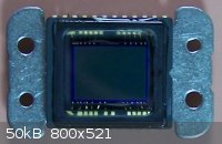
Watson you sound like the CCD expert here, what do you think about the one in the DSC-F707 or 717 Digital Still Cameras? Don't have the part number
easily available right now. I have 4 of the 707's and 3 of the 717's. Half of them have had the CCD fail which I replaced by ordering the CCD's from a
seller on ebay. Very hard job as they had to be soldered in after removing the original parts. While I do not have a clean room and the optical
assembly had to be disassembled, they all take fantastic pictures. Meaning I do not think they collected very much microscopic dust during the work. I
will have to go through the junk box for one of the old units and see if a number is printed on it. They are 5 megapixel, the camera is 12 mp
including the digital processing. One problem is these things seem to fail far too often, I have read Sony had troubles with some kind of
manufacturing defects in this line of CCD's. This makes me worry if the work is worth being done based on this part. I only bring it up as somewhere
in a box I still have a new replacement spare, but no data sheet. Are you familiar with the CCD in this camera line and know where a handy PDF link
for the CCD is?
Also would you start this project using one knowing the failure of the CCD was the most common failure for the model series?
I just thought of this: Since I have dozens of the 707's and 717's as spare parts I have plenty of components. One part was an IR filter in a holder
controlled by a solenoid. In nightshot mode the solenoid moves the filter out of the way and alters the focus to compensate for the shift. It is 1.24
mm thick, 12.95 mm X 10.95 mm in size. Since the green lasers usually also have significant IR output would it make sense to add one of these after
the laser so that only the green light made it into the rest of the assembly?
[Edited on 3-8-2013 by IrC]
"Science is the belief in the ignorance of the experts" Richard Feynman
|
|
|
radagast
Hazard to Self
Posts: 79
Registered: 28-6-2012
Location: NYC
Member Is Offline
Mood: No Mood
|
|
(1) BTW, while browsing W's laser blog, I came across his designs for a CCD driver, which uses the ILX553B CCD:
http://redlum.xohp.pagesperso-orange.fr/laser/gratingOSA.htm...
(2) I was puzzled as to why I kept on getting that strange background hump in the aspirin spectra, when there was no mention of any baseline
correction in the Mohr et al. article. Then it dawned on me (facepalm) that I was using a laser that was at least several times more powerful than
the 5 mw laser used there. Assuming that fluorescence doesn't increase equally across the wavelength range while cranking up the laser's power (and
I don't see why it would), this might account for the background hump.
The logical solution would be to decrease the laser power (maybe with a variable resistor?) but I first tried lowering the integration time from 3
seconds (as described in the paper) to .7 seconds. The result was a substantially flatter baseline. Not quite there yet, but getting there . . .
Attachment: GKau (Reduced Integration Time) Raman Spectra.pdf (12kB)
This file has been downloaded 783 times

[Edited on 9-3-2013 by radagast]
|
|
|
IrC
International Hazard
Posts: 2710
Registered: 7-3-2005
Location: Eureka
Member Is Offline
Mood: Discovering
|
|
How much improvement do you think there would be to have the laser diode heatsinked with a thermoelectric cooler to reduce mode hopping and other
effects which I believe could be considered as adding noise to the desired signal?
"Science is the belief in the ignorance of the experts" Richard Feynman
|
|
|
watson.fawkes
International Hazard
Posts: 2793
Registered: 16-8-2008
Member Is Offline
Mood: No Mood
|
|
| Quote: Originally posted by IrC | Watson you sound like the CCD expert here, what do you think about the one in the DSC-F707 or 717 Digital Still Cameras? Don't have the part number
easily available right now. [...] Are you familiar with the CCD in this camera line and know where a handy PDF link for the CCD is?
[...]
Also would you start this project using one knowing the failure of the CCD was the most common failure for the model series? |
A bit of internet searching yielded the part number: Sony ICX282. Here's its new product announcement. Datasheet is attached. The biggest problem you'll have with using a camera chip is that the drive circuitry is
significantly more complicated. While looking this up, I also found the Sony CXD2498R, a 48-pin chip specifically design to drive the CCD. You'll need
much of the capacity of such a drive chip, so you can either use one or implement what you need of one with a microcontroller. Frankly, I can't see
the advantage unless someone else had already done the engineering work. It's a good bit of work to fiddle with all that signal generation. For
personal use, almost everybody's time-vs.-money tradeoff would seem to indicate just buying a linear sensor chip. They are much, much easier to
interface.
As to the issue of reliability, if you've got lots of them, then there's your reliability solution. | Quote: Originally posted by IrC | | Since the green lasers usually also have significant IR output would it make sense to add one of these after the laser so that only the green light
made it into the rest of the assembly? |
I doubt it. The IR band in a spectrometer is typically not shining on
the CCD, so it won't introduce much noise if its internal optical table is moderately-well built.
Attachment: ICX282AQ, Diagonal 11 mm Frame Readout CCD Image Sensor, Sony.pdf (522kB)
This file has been downloaded 872 times
|
|
|
watson.fawkes
International Hazard
Posts: 2793
Registered: 16-8-2008
Member Is Offline
Mood: No Mood
|
|
| Quote: Originally posted by radagast | | Assuming that fluorescence doesn't increase equally across the wavelength range while cranking up the laser's power (and I don't see why it would),
this might account for the background hump. |
Fluorescence is the absorption and re-emission of photons, so
its emission spectrum is generally independent of the pumping energy. Emission lines are doppler-broadened for each transition, so with (a) a
room-temperature sample and (b) a spectrometer that doesn't discriminate with really fine resolution and (c) a laser with a broad emission spectrum
and (d) and an organic sample with lots of transitions, you'll end up with a big hump like you're seeing. (a), (b), and (c) each contribute their own
convolution width, and (d) means you're summing more than one Gaussian together.
What to do about it is another thing entirely. In the time-resolution paper I posted up-thread, they're using extraordinary sharp pulses and using a
photomultiplier tube in single-photon mode to count. They're not doing simultaneous measurements at different frequencies; they're scanning. So that's
not the easiest way to improve fluorescence rejection.
Other than improving the quality of all the components, the easiest thing to me seems to take advantage of the different ways that Raman scattering
and fluorescence behave with respect to frequency. The Raman spectrum will be shifted when you change pump frequency (by rotating the prism); the
fluorescence spectrum won't be. Some signal processing allows nulling out the bulk of the fluorescence. You can take spectra at different frequencies
by monochromating the laser. Run the beam through a prism to disperse the green beam. Use a lens to put the rays parallel again after you've got
enough separation. Then use a slit to select a pump frequency.
To estimate how well this might work, compute the wavenumber shift for ( 532 +/- 3 ) nm. That's what you can reasonable get out of a laser with an 8 nm emission width. That number is around 212
cm-1. At +/- 2 nm, it's 141 cm-1. At +/- 1nm, it's 71 cm-1. (Note that this is roughly 35 cm-1 per nm of
pump wavelength difference.) The broadest peaks are aroung 50 cm-1 (roughly), so even a fairly small pump wavelength difference would
suffice to get good peak separation.
|
|
|
watson.fawkes
International Hazard
Posts: 2793
Registered: 16-8-2008
Member Is Offline
Mood: No Mood
|
|
| Quote: Originally posted by IrC | How much improvement do you think there would be to have the laser diode heatsinked with a thermoelectric cooler to reduce mode hopping and other
effects which I believe could be considered as adding noise to the desired signal?
|
There are lots of sources of laser width broadening. This one would do something, but frankly I just don't
know how much difference this one technique would make when compared to all the others that are possible. We're not relying on any of the coherence
properties of a laser as an illumination source here, only monochromaticity. It would seem that building an optical train to monochromate the laser
would be the cheapest way to narrow the wavelength width of the illumination.
The longer answer is that these 532 nm lasers are a three-stage system. They use (1) an IR laser diode to pump (2) an Nd-doped crystal whose output is
then (3) run through a frequency-doubler. It's component (2), with all of the different transition lines, where the bulk of the frequency noise comes
from. The issue is that it's the partition of energy in the Nd-excited states that matters. The thermal broadening of the individual Nd peaks is far
less important as a source of noise than is the multiplet structure of the Nd transitions (see my post about with some of the spectroscopic data).
Selectively pumping only a single transition in the Nd would seem to be the first thing to do, but that requires re-building the laser emitter system.
|
|
|
IrC
International Hazard
Posts: 2710
Registered: 7-3-2005
Location: Eureka
Member Is Offline
Mood: Discovering
|
|
If you are designing a new highly expensive instrument with deep pockets building your laser from scratch sounds like a good idea. But if you are a
poor bastard like me working with surplus the prefabricated diode is all that makes sense. Would in these circumstances it make more sense to build a
filter as rigidly as feasible in poor bastard dollars such as below. Also what is the proper width of the two slits and could a grating with proper
line spacing work? This includes the question what should the spacing be (in microns or nanometers, or even lines per inch if a grating?). Seems if
frequency is varying and the laser power was high enough (so that enough light of proper frequency always reached the target), hopefully only the
frequency desired would reach the target. Also I still don't know if adding the IR filter from a surplus DSC-F707 right after the diode (as we know
usually there is much IR from the pump diode IIRC around 900 nm) would improve things. Seems to me reducing any IR would help in reducing signals
caused by excitation of the target by undesired frequencies. Then again if the filter shown was added one would think the filter would stop the IR.
Another thought is at what rate would optical power at the desired frequency vary? Slower than sampling times thereby removing it from concern? Seems
like mode hopping would be much quicker than the window of sampling time.
[Edited on 3-10-2013 by IrC]
"Science is the belief in the ignorance of the experts" Richard Feynman
|
|
|
watson.fawkes
International Hazard
Posts: 2793
Registered: 16-8-2008
Member Is Offline
Mood: No Mood
|
|
| Quote: Originally posted by IrC | | Would in these circumstances it make more sense to build a filter as rigidly as feasible in poor bastard dollars such as below. Also what is the
proper width of the two slits and could a grating with proper line spacing work? |
A monochromator made from
an optical train would eliminate the need for an IR filter, because the IR wavelengths would be rejected along with everything less. There's a
tradeoff between power, frequency selectivity, and sampling time, certainly, but it's not like amateurs need to run highly-accurate spectrum in less
than a minute.
The monochromator chain in the illustration would work fine. It's built entirely from reflective elements (mirrors), but it would also be possible to
use transmissive elements (lenses).
As for the exact parameters for designing a system, it's impossible to say categorically. The system actually needs to be designed. There are just too
many variables to say anything, such as the focal lengths of the mirrors, the distances between elements, etc. I'd recommend learning the paraxial-ray approximation and the matrix method of analyzing them. It's a way using 2-by-2 matrices to model optical trains. It works very well for first-cut analysis of most
optical systems. If you need more, for example to deal with chromatic aberration, you'll need frequency-specific ray tracing or its ilk. This method
of analysis should be present in pretty much every introductory physics textbook on optics. An abbreviated treatment (adequate at least to get
started) is in Building Scientific Apparatus. It's now in 4th edition, but previous editions are adequate for many purposes (except
electronics, which always moves too fast).
|
|
|
IrC
International Hazard
Posts: 2710
Registered: 7-3-2005
Location: Eureka
Member Is Offline
Mood: Discovering
|
|
Thanks Watson I'll do some study on that. Do you have a diagram laying around of the filter using lenses instead of mirrors. That one I have not seen.
I picture a series or somewhat offset inline set of lenses (and slits?) where each following lens is set to only catch the light spread out unequally
by frequency (chromatic aberration) of the desired wavelength. I had figured the IR blocker would not be needed with the filter as it would be outside
of the slit. Never hurts to be sure though. I was assuming some of my blues really put out a lot of IR. Even with my glasses for the blue laser on I
have noticed after cutting things for a while my eyes feel fatigued and a little painful similar to too much time up north in the snow on a bright
day. Very similar. This led me to believe there is excessive light I cannot see which the glasses are not blocking. Whether IR (most logical) or UV I
do not know. I can say the eye pain is similar to too much UV I have encountered in Arctic hiking. However I have in the past felt this with high
powered IR before so it seemed most logical considering the pump laser in the blue diode assemblies.
Thanks for the PDF's. I had the service manual for the camera line but when I checked Sony a few years ago I could not find the PDF's you just found.
I admit it would be much work but I had been thinking one does not need to address the entire CCD. Using the correct center scan mode and only looking
at a portion of the vertical would simplify things. I was also thinking ignoring the green pixel data would be another level of blocking the laser
from the desired signal. Of course if the material being studied had lines right in that area this would be a bad idea as information would be lost.
Then again using a green source would seem to do this anyway, I assume this is why some common commercial units use IR, to give a wide spectral range
for the desired information. Another thought was using the input for substrate bias like an electronic shutter. You are right though it would be a
hell of a long and complex project.
The reason I was bringing up the IR filter was from study of the pic in my first post above. I could not see what else they meant by 'laser cleaning
optic'. A bandpass filter would be expensive. Your idea is simply build a cleaner laser but I think this is outside the money and technical abilities
(or at least equipment) of the average amateur. I assumed the filter radagast sent me is for blocking the green just ahead of the spectrograph. Since
the pic was produced by an entity which builds these devices I could not fathom why the cleaning optic would be there if not needed. What is annoying
is the lack of information and precise data nearly everywhere I search the subject. Nearly is too weak, pretty much every explanation out there is
vague and generic.
[Edited on 3-12-2013 by IrC]
"Science is the belief in the ignorance of the experts" Richard Feynman
|
|
|
Marvin
National Hazard
Posts: 995
Registered: 13-10-2002
Member Is Offline
Mood: No Mood
|
|
The things that make this project so feasible are the spectrometer (200 USD is cheap), the cheap edge filter (45USD for the dichroic or the Schott
OG550 for a little less), the wide availability of cheap DPSS laser pointers and reports from two people that it actually works. It may be best if
further speculation on general methods are put with the rest in the big Raman thread.
IrC,
If you can afford the spectrometer I would recommend going with it, the default grating is even right for Raman. They are sparsely on ebay and should
the supply dry up there is nothing close. It is possible with tweaking this setup will be good enough for useful chemistry. Otherwise you'll be
working hard and spending money just to get a signal.
IR will go right through the low pass. The Stokes shifted light we want may be 4 or more orders of magnitude weaker than the returned laser line. IR
Reflections, scratches on the grating etc may swamp the detector. Spectrometers aren't designed to provide this level of out of band rejection. IR
may even produce it's own Raman spectrum with enough intensity to appear over the top of the signal we want (reflected by the grating at higher n
unless we have an order sort filter).
We don't need an expensive bandpass filter for the laser, just something to block the 808 and 1064 lines. A regular IR filter may do the job. Trial
and error will tells us what we can get away with.
Briefly about building a spectrometer with lenses, aside from chromatic aberration, every optic element introduces a new set of reflections. It can
be done well with SLR camera lenses which avoid many problems but this is not a cheap option.
|
|
|
IrC
International Hazard
Posts: 2710
Registered: 7-3-2005
Location: Eureka
Member Is Offline
Mood: Discovering
|
|
Only ones I've seen so far range from a grand to three. In my searching I did find some useful info and a few patents which might be worth reading.
http://www.oceanoptics.com/Applications.asp
Patents Title
7,149,033 UV visual light beam combiner
6,839,176 Composition and method of making high-reflection silver mirrors or thin-film optical filters
6,700,690 Tunable variable bandpass optical filter
5,381,505 Optical fibers with a light absorbing coating
6,638,668 Patterned filters for spectrographic imaging
5,711,889 Methodology to make optical filter arrays
4,884,697 Surface profiling interferometer
20090189513 LED using thin film dichroic filters
20090028756 Patches for non-intrusive monitoring of oxygen in packages
20080199360 Method and composition for a platinum embedded sol gel optical chemical sensor with improved sensitivity and chemical stability
20070122311 High performance materials for optical sensors for hydrocarbons environment
20070052961 Method for extending the color gamut for dichroic color mixing systems and colored gobos
20060092520 UV visual light beam combiner
Ag+ Coatings for improved reflectivity in VIS region Tunable variable bandpass filter
Forgot to ask but you didn't post a link. I did some searching here and I believe you mean "Laser-Diode based Raman Spectroscopy"?
From the prices I have seen searching thus far, I think I will try building my own spectrometer from the ground up. I have single lens reflex cameras
and parts from years of rebuilding them as a hobby. Wonder if one of my 58 mm Zeis lenses would be useful in this. As for gratings 600 mm-1 and 1,000
mm-1 are two common choices. I have 531.49 mm-1 and 1,000 mm-1 so that is a start. What I absolutely cannot find are low cost slits, .25 um, 50, 100,
and a few wider. I Cannot think of a low cost hacker way to build them with precision.
[Edited on 3-14-2013 by IrC]
"Science is the belief in the ignorance of the experts" Richard Feynman
|
|
|
radagast
Hazard to Self
Posts: 79
Registered: 28-6-2012
Location: NYC
Member Is Offline
Mood: No Mood
|
|
D'oh
Welp, the good news is that I'm going to get more practice calibrating these DIY spectrometer units, and will document my next experience carefully as
soon as I crack open my new spectrometer.
The bad news is: development on the raman spectrometer came to a screeching halt after I accidentally plugged my netbook power supply into my (prior)
spectrometer unit and likely destroyed it. Let this be a lesson to y'all to not keep a cobweb of power cords under your workbench, which is exactly
what I did.
BTW, before destroying the unit, I got a nearly-flat baseline spectra for aspirin by using a Radioshack potentiometer to reduce the current and thus
the laser power.
@IrC: I believe Marvin has one of these DIY spectrometers already, so if you'd like to take a crack at rescuing this old
spectrometer and using it yourself, I'd be happy to mail it to you sometime this month for free. I looked inside but couldn't find any fuse, and have
a feeling that any repair is simply beyond my circuit trouble-shooting abilities, but I bet you can do better since you know more about circuits.
|
|
|
IrC
International Hazard
Posts: 2710
Registered: 7-3-2005
Location: Eureka
Member Is Offline
Mood: Discovering
|
|
This is a question for Watson. I found this Color Light Sensor for 5 bucks for the Arduino. 10 bit resolution and real easy programming. I wondered if
it would not be too insane to consider maybe gluing the sensor off center to a small dynamic mike element. If the other side was held rigid, a small
microvolt DC voltage (or a sawtooth?) could make it scan a line across the grating. What do you think?
https://www.sparkfun.com/products/10656
No doubt other ideas to make it scan exist, I was just thinking about the complexity of writing software to address a CCD as opposed to trying
something like this. They even provide sample code and other useful info for free which make it very easy to get data from this sensor.
So have I gone off the hacker deep end or do you see this as something useful?
"Science is the belief in the ignorance of the experts" Richard Feynman
|
|
|
watson.fawkes
International Hazard
Posts: 2793
Registered: 16-8-2008
Member Is Offline
Mood: No Mood
|
|
| Quote: Originally posted by IrC | | I wondered if it would not be too insane to consider maybe gluing the sensor off center to a small dynamic mike element. |
The photodiode on that chip is 420 microns square, per its data sheet. The width of the pixel on the ILX511 is 14 microns, a factor
of 30 smaller. It's conceivable, barely, that you could deconvolve the signal from a moving fat pixel and get reasonable data out. I don't recall off
the top of my head how the error analysis goes, but I'm not optimistic. I don't recommend it. A $45 linear CCD chip is a much better investment than a
$5 sensor and a bunch of electromechanical bother. (Plus it's a BGA device; I hope you can get it mounted.)
|
|
|
IrC
International Hazard
Posts: 2710
Registered: 7-3-2005
Location: Eureka
Member Is Offline
Mood: Discovering
|
|
I have 3 Sony CCD's for the DSC-F707/717 which was my plan. Nice to have a couple backups since I have a dozen of the still cameras, and the CCD likes
to go black far too often. Only cure is a new CCD. Never know when one will be needed, I have had to replace 3 of them so far as it is. I saw this
simple $5 sensor and how easy the code was so I had to wonder about it. Still stuck trying to find any kind of optical slits. Damn impossible to find
and harder to make with precision. Would be nice if one existed with a micrometer adjustment at low cost. Honestly I cannot find any reasonable source
whether fixed or adjustable for the hardware hacker, even at unreasonable cost. I wish I could think of a good surplus cheap source for optical slits.
"Science is the belief in the ignorance of the experts" Richard Feynman
|
|
|
| Pages:
1
2
3
4
..
10 |


