| Pages:
1
2
3
4
5
6
..
10 |
SM2
Hazard to Others

Posts: 359
Registered: 8-5-2012
Location: the Irish Springs
Member Is Offline
Mood: Affect
|
|
Another great place to source a cheap but excellent beam splitter is from some of the members on http://laserpointerforums.com/. They are very helpful, and will get you what you need at a very affordable price.
"Old men who speak of victory
shed light upon their stolen life
they - drive by night- and act as if they're
moved by unheard music." B. Currie
|
|
|
aga
Forum Drunkard
Posts: 7030
Registered: 25-3-2014
Member Is Offline
|
|
Quick thought on a variable Slit :-
Assuming that the razor blades are as straight as anything will ever be, you could mount 2 of them vertically on a disc (maybe a gear with pre-drilled
centre hole) with each one being offset from centre by a small amount.
Looking from the side, the width of the apparent 'slit' will vary depending on how the disc is rotated.
Your work on this is wonderful. Truly inspiring.
[Edited on 17-4-2014 by aga]
|
|
|
aga
Forum Drunkard
Posts: 7030
Registered: 25-3-2014
Member Is Offline
|
|
Stick a couple (or a few) small neodymium magnets to the razor blades.
Vary the distances, and polarities.
Should be possible to set the Gap distance that way without the magnetised blades sticking to each other (untried idea).
An alternative is green rizla cigarette papers : 0.01 mm thick.
Use them as packing at the top and bottom of the razor edges.
I still use a folded rizla paper to set the meshing of the pinion to the drive gear on model helicopters. Works a treat.
|
|
|
aga
Forum Drunkard
Posts: 7030
Registered: 25-3-2014
Member Is Offline
|
|
Yo!
Tell us how it is going.
There should be a separate or sticky for this.
It is important.
|
|
|
Neotronic
Harmless
Posts: 3
Registered: 4-10-2014
Member Is Offline
Mood: No Mood
|
|
Spectrum studio CSV file modification
Hello to everyone, this is my very first post on this forum.
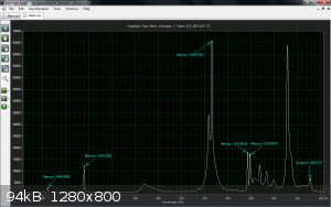
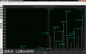
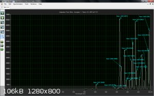
I just want to share my modification of Science Surplus Spectrometer. Instead of calibration of squeezing the spectrum into wavelenght range, my
approch was, Calibrate the spectrum adjusting the bottom pixel numbers as wavelenght. Basically in the graph normally you see wavelenght from 0 to
2048. I have modified the CSV. file to show from 383nm - 642nm. I have created a exel file to modify this range, and using Osram and Neon i have
calibrated this table. For thouse who find this solution helpfull i can share and explain how it is possible. My another modification was to make this
spectrometer possible to use internal and external CCD Linear Sensor IC SONY CDIP-22 ILX511 but that will be another post.. 
|
|
|
aga
Forum Drunkard
Posts: 7030
Registered: 25-3-2014
Member Is Offline
|
|
Welcome, and nice effort.
What do you use for a Filter ?
|
|
|
Neotronic
Harmless
Posts: 3
Registered: 4-10-2014
Member Is Offline
Mood: No Mood
|
|
I don't use any filter, The light from osram fluorescent bulb, and neon bulb is comming direct via optical cable to Spectrometer. The slit is 50um.
|
|
|
aga
Forum Drunkard
Posts: 7030
Registered: 25-3-2014
Member Is Offline
|
|
I meant for the actual Raman back-scatter thing.
What filter do you use for eliminating the Source/excitation light ?
|
|
|
Polverone
Now celebrating 21 years of madness
Posts: 3186
Registered: 19-5-2002
Location: The Sunny Pacific Northwest
Member Is Offline
Mood: Waiting for spring
|
|
Looks like someone figured it all out. The ramanPi: http://hackaday.io/project/1279-ramanpi-raman-spectrometer
PGP Key and corresponding e-mail address
|
|
|
DistractionGrating
Hazard to Self
Posts: 68
Registered: 3-4-2014
Member Is Offline
Mood: Precipitated
|
|
Sweet!
|
|
|
smaerd
International Hazard
Posts: 1262
Registered: 23-1-2010
Member Is Offline
Mood: hmm...
|
|
That is hands down the most impressive open source project I've seen to date. Now I want a 3-D printer... Would make aquiring a lot of the components
necessary for all these projects so much more accessible.
|
|
|
IrC
International Hazard
Posts: 2710
Registered: 7-3-2005
Location: Eureka
Member Is Offline
Mood: Discovering
|
|
This project is so complex it is not easy to quickly locate additions, I cannot find calibration info (http://hackaday.io/project/1279/instructions) beyond this : Section: 9 Spectrometer Calibration has not been written yet.
Appears not finished yet, nor can I find information as to when it will be. Also I wonder what radagast is doing it's been well over a year since any
word or posts but it appears at least he did check in about a month ago.
I should have listened to bfesser and picked up a RaspberryPi a year or two ago so I would have a head start on using one. Sticking to my Pics,
Arduinos, ATMegas and whatnot I have spent zero time learning about the Pi. More work to do. I did download the 114 mb file
ramanSpectrometer-master.zip. Need to unzip and look at these files. I see no reason a skilled craftsman cannot replicate important components without
investing in a 3D printer. From all the pictures this looks feasible yet incredibly involved. May make alignment (http://hackaday.io/project/1279/log/9812) more difficult, not sure yet. The large zip contains .stl files but dealing with files for 3D printers
is not something I have experience with yet. I assume they are in a code format for the printer, can anyone say if these .stl files can be converted
into blueprints for study? Doubt I'll have the money to buy a 3D printer anytime soon.
"Science is the belief in the ignorance of the experts" Richard Feynman
|
|
|
aga
Forum Drunkard
Posts: 7030
Registered: 25-3-2014
Member Is Offline
|
|
Wow ! That is an amazing find Polverone.
The biggest cost always seems to come down to the filters.
Has anyone experimented with making their own edge/notch filters, or is that seriously difficult ?
|
|
|
IrC
International Hazard
Posts: 2710
Registered: 7-3-2005
Location: Eureka
Member Is Offline
Mood: Discovering
|
|
FYI on the .stl files.
http://www.hive76.org/rendering-stl-files-to-images
https://github.com/robottrouble/STLRender
http://www.robottrouble.com/projects
http://www.povray.org/
"Science is the belief in the ignorance of the experts" Richard Feynman
|
|
|
aga
Forum Drunkard
Posts: 7030
Registered: 25-3-2014
Member Is Offline
|
|
OK. Here's an idea for removing much of the Source wavelength.
How about a beam splitter Before the laser enters the sample, then a moveable pair of mirrors taking the other 50% to be recombined with the Raman
scattered vector, then adjust the mirrors to be exactly 180 out of phase with the source.
Plus some kind of simple filter to adjust the 'brightness' to match that of the original source, which is always present along with the Raman
component.
By adjusting the path-length, the second beam (theoretically) could be made to destructively interfere with the original laser light, effectively
cancelling it from the image, leaving Only the Raman spectra.
Yes, a Notch filter would be much easier, yet financially out of reach of most amateurs.
|
|
|
Marvin
National Hazard
Posts: 995
Registered: 13-10-2002
Member Is Offline
Mood: No Mood
|
|
Don't forget that cancelling out a beam violates conservation of energy. Practical methods result in reflecting dichroic filters. The Schott filter
(OG550 was it?) is pretty inexpensive.
There are a lot of ghetto methods but the spectrum is only a fraction of the way to a useful instrument. It may be that a version with poorer specs
made from cheap mass produced parts would be much more use than a few one off units operating independently. It may be that every tiny flaw in a
home made device is going to cause merry hell getting comparisons to every other unit.
The RamanPi I think has yet to produce it's first Raman spectrum, I stopped following it closely when the pages became so large they crashed my
netbook.
|
|
|
IrC
International Hazard
Posts: 2710
Registered: 7-3-2005
Location: Eureka
Member Is Offline
Mood: Discovering
|
|
Quote: Originally posted by Marvin  | | The RamanPi I think has yet to produce it's first Raman spectrum, I stopped following it closely when the pages became so large they crashed my
netbook. |
I have gone through pretty much everything and believe the answer is still no but 8 days ago FlatCat wrote: "I'll be re-writing the firmware for the
imagingBoard in the next few weeks". The calibration is not yet written either so I doubt useful data on a real test has been produced thus far. You
are right this project is massive. Right now he has a couple other projects on the main menu page I am finding even more interesting and less costly.
"Science is the belief in the ignorance of the experts" Richard Feynman
|
|
|
aga
Forum Drunkard
Posts: 7030
Registered: 25-3-2014
Member Is Offline
|
|
Thanks for the filter code.
A quick ebay popped up a surprise :
http://www.ebay.co.uk/itm/550nm-Filter-for-IPL-Beauty-Treatm...
|
|
|
John Green
Harmless
Posts: 14
Registered: 4-2-2015
Member Is Offline
Mood: No Mood
|
|
New to discussion board.
Has anyone any experience with the above filter?
|
|
|
m1tanker78
National Hazard
Posts: 685
Registered: 5-1-2011
Member Is Offline
Mood: No Mood
|
|
No first-hand experience but the specs indicate ~70nm transition from the stopband to ~50% transmittance. It would certainly be useful for attenuating
the laser line (assuming excitation wavelength is 532nm?) but would also attenuate the Stokes-shifted peaks near the laser line. This type of filter
can't be fine tuned, unfortunately. They're cheap enough to buy one and try it out.
Chemical CURIOSITY KILLED THE CATalyst.
|
|
|
m1tanker78
National Hazard
Posts: 685
Registered: 5-1-2011
Member Is Offline
Mood: No Mood
|
|
I'm in the process of gathering bits and pieces to construct a Raman spec which will use 650nm as its excitation wavelength. After a lot of back and
forth, I decided to base the concept around measuring the anti-Stokes scattered light. I don't fully understand how Stokes scattering
can be more intense yet, lower energy than anti-Stokes?!? Leaving that out of the equation for the purpose of moving forward, most CCDs have better
sensitivity at <650nm than they do in the NIR anyway. That was an important sticking point for me when choosing how to model the concept.
++++++++DETECTOR:++++++++
The detector I chose and purchased is a TCD1705D made by Toshiba. It's a 7450 element linear CCD.
++++++++ELECTRONICS:++++++++
I have a variety of Altera FPGA boards and ADCs for pulse generation, signal collection and processing, and communication to/from a PC or laptop. I'm
going to try to model this design phase around a relatively inexpensive Cyclone IV development board as well as an 8 bit ADC to read the analog charge
levels on each pixel and forward to the PGA. I've tentatively chosen the TLC594IP as an entry point in spite of being only 8 bits. It's integrated on
the dev board and should be fine at least for testing purposes.
++++++++SOFTWARE:++++++++
Haven't decided yet. I plan to establish a USB link between the FPGA and the PC/laptop to gather the data and control the CCD integration time and
possibly laser on/off and power level. I don't want to get bogged down with writing drivers and fighting Microsoft all along the way so I might target
Linux instead. I'm comfortable with Python and C/C++ (like riding a bycicle, I hope). Most or all DSP will be performed within the FPGA so if worst
comes to worst, good old RS232 will be plan B. Graphing is pretty straight forward under Linux. Additional DSP can easily be performed if needed.
++++++++OPTICS:++++++++
I purchased a few shortpass filters from Edmund in which the technical notes say that a 0* angle of incidence is the normal mode of operation. That
turns out to be wrong; the filters have the usual 45* AOI as the norm. The reasons I bought several are:
---1. Can be used as laser line cleanup filters.
---2. Are 'OD >2.0' so I may need to chain more than one for max laser line rejection.
---3. Would rather use edge filters than notch (don't care about anything at or above laser line).
---4. Claim to have a sharp cutoff transition and good characteristics in and out of band.
If I can find a relatively inexpensive spectrometer I might forgo the front face reflectors and diffraction grating. In keeping with my design model
and goals, I'll still experiment first with off the shelf optics as well as CD/DVD/BR for the grating. I have some ideas for an
electronically-controlled slit but don't want to get sidetracked so will stick to good ol' razor blade slit and magnets.
++++++++GENERAL DESIGN AND CONSTRUCTION FLOW:++++++++
I'll begin work on the detector side of the design. Having a working CCD/ADC/FPGA/PC chain should help tremendously when it comes time to align
optics, establish baselines and characterize filter response.
Next will be slit to detector chain. This phase of the design can be tested with ordinary light sources. No need to fire up the laser and mess around
with samples until bugs are worked out in this phase. Standard light sources such as a neon lamp can be used to establish known spectral line
positions, make adjustments, etc.
From there, the laser source to slit phase will be constructed. After characterizing the laser line(s), a cleanup filter will be added along with
sample holder and edge filter(s). I may elect to add one or two reference sources as well but generally want to avoid using beam splitter(s) if
possible. Since the design will be open box or breadboarded at this point, I will first use a low power laser in spite of wearing safety glasses rated
for 650nm.
The rest is tweaking and building an enclosure. This is where I'm tentatively going to free myself to get sidetracked on adjustable mounts, adjustable
slit, whatever. (I have a tendency to get sidetracked on my projects-- need to keep it in check!). 
Suggestions, discussion and testimonies are welcome. For now I'll start work on coding the CCD driver.
=====================================
Technical specs and datasheets:
DETECTOR: TCD1705D
ADC: TLC549IP
EDGE FILTERS: EDMUND #47-290
FPGA: CYCLONE IV E SERIES
Chemical CURIOSITY KILLED THE CATalyst.
|
|
|
John Green
Harmless
Posts: 14
Registered: 4-2-2015
Member Is Offline
Mood: No Mood
|
|
Tanker,
The reason Stokes is often used rather than anti-stokes radiation is that the stokes lines are generally more intense and the reason for that is:
The probability of an anti-Stokes transition is much less than that of a Stokes transition, since at room temperature the majority of molecules
present are in the lowest vibrational level.
From the Wikipedia article Stokes Line.
The anti-stokes shift is of course derived from the vibrational energy (temperature) of the molecule.
In fact the ratio can be used to measure the temperature of the sample.
|
|
|
Marvin
National Hazard
Posts: 995
Registered: 13-10-2002
Member Is Offline
Mood: No Mood
|
|
TCD1705D is awesome for resolution but about 20 times less sensitive than the ILX511 or TCD1304AP. Mainly I think due to the pixels being tiny and
square.
The short pass filters are not edge filters, looking at the OD plot they are very soft. This may be due to the 45degree angle design. The only sharp
45 degree filter I could find was an uber expensive holographic notch filter. They might work stacked but as John confirmed anti-stokes will cost you
much more signal. Maybe a factor of 10.
|
|
|
m1tanker78
National Hazard
Posts: 685
Registered: 5-1-2011
Member Is Offline
Mood: No Mood
|
|
Looks like I'm headed down the wrong path. Those factors are a recipe for failure. It's not too late to rethink the detector. I'm putting the
finishing touches on the tcd1705d's firmware so I'm going to go ahead and get it working before I scout around for a better detector.
I understand that Stokes-shifted signals carry more intensity but the detectors' response drops off in that region of the spectrum. The detector's
response peaks in the anti-Stokes region in contrast.
With full control of the detector's integration time, I'm hoping to be able to capture some useful spectra at good resolution even at the expense of
time.
I've been promised a holographic notch filter but it's intended for 632-ish nm and I don't have a HeNe laser source at my disposal.
The dichroic filters are what they are. I'll just have to make do with them for now.
Chemical CURIOSITY KILLED THE CATalyst.
|
|
|
John Green
Harmless
Posts: 14
Registered: 4-2-2015
Member Is Offline
Mood: No Mood
|
|
I am surprised that I hadn't seen this sooner as I had been expecting and looking for a development like this for some time. As long as these things
stay in laboratories they remain ridiculously expensive. Until a product that appeals to Joe the beer drinker down at the tavern it won't be cheap.
I suspect spectrometry is nearing that point. Technology is getting to the point that these things can be put on a chip and information technology is
nearing the point that no brains are needed to interpret the result.
There have been on-chip implementations before but they have been low resolution color measurement devices. At 1nm resolution and low f# this one
just may be different.
http://www.opticsinfobase.org/view_article.cfm?gotourl=http%...
[Edited on 26-2-2015 by John Green]
|
|
|
| Pages:
1
2
3
4
5
6
..
10 |


