| Pages:
1
..
6
7
8
9
10 |
m1tanker78
National Hazard

Posts: 685
Registered: 5-1-2011
Member Is Offline
Mood: No Mood
|
|
Using a fluorescent work light, I aligned the optics so that the green portion of the visible spectrum falls roughly on the center of the detector. I
also wrote some code to invert the data in the FPGA. I added a status packet that includes the minimum and maximum values so that the graph will
automatically adjust accordingly. It's not yet clear to me how far out from the laser line I'll need to capture for useful Raman work. For the time
being, I simply included most of the visible portion of the spectrum in the detector's field of view.
So far, the resolution of the prototype spectrometer is considerably higher than what I hoped for when I started on the project. I would have been
satisfied with 2:1 pixel:nm. I calculated that in its current state, there are roughly 13 pixels per nm of resolvable wavelength. To put it another
way, if the spectrometer is illuminated with 2 light sources -- one with wavelength of 500nm and the other 510nm, the distance between the peaks will
span ~134 pixels. IIRC, the deviation across the spectrum is non-linear but I'll need to revisit the books.
The raw output produces a forest of 'garbage' unrecognizable spectra to the untrained eye. Some of the peaks are only a handful (or less) pixels wide.
These are unfortunately washed out even with non-aggressive averaging/smoothing like Marvin had mentioned.
Two lightly smoothed and stacked exposures of the fluorescent light:

Since much of the apparent noise in the raw data appears to be non-random, I've been giving some consideration to pixel-wise PRNU correction as
mentioned before. That and a way to reliably produce evenly illuminated frames. Up until today, I hadn't seriously considered calibration light
sources (neon, argon, LED, etc) and where/how to install them. If a miniature CFL existed, that would be at the top of the list for sure!
Chemical CURIOSITY KILLED THE CATalyst.
|
|
|
tvaettbjoern
Harmless
Posts: 28
Registered: 25-2-2016
Member Is Offline
Mood: No Mood
|
|
I'm slightly jealous, I'm still waiting for the new PCB before going further.
Maybe I missed from a previous post, but I'm curious what kind of laser you're using. Is it a green DPSS? I'm very interested to see how you'll get a
stable laser. I cheated and bought a used commercial lab laser.
For Raman you'll want to be able to record up to 4000 cm⁻¹, which with a 532 nm laser corresponds up to around 670 nm (assuming you're not
interested in the anti-Stokes scattered light)
With a 532 nm laser, you should have something like 26 pixels/nm.
What the actual resolution of your spectrometer will end up being is function of slit width, number of illuminated lines on the grating, and how well
you'll be able to focus the slit onto the CCD (and a lot of complicated stuff related to the abberations present in the design of your particular
spectrograph). And if you find a way to quantify this I would love to hear 
|
|
|
m1tanker78
National Hazard
Posts: 685
Registered: 5-1-2011
Member Is Offline
Mood: No Mood
|
|
I'm prototyping with a 650nm laser. The original plan was to use 650nm and collect the anti-Stokes Raman scattering. AS lines are
said to be much weaker but the detector is most sensitive in that region. I wanted to avoid short wave illumination if possible to reduce
fluorescence. Details are upthread a couple of pages.
Slit width can be closed but even at the current aperture, the intensity of light striking the sensor is minuscule. I would think that it would need
to be opened up a bit for Raman work (though I haven't tried). I'm prototyping with a cheap red laser pointer but will move to a better 650nm source.
If that doesn't pan out, I can install a green laser and capture the Stokes rather than anti-Stokes. It will be much simpler to experiment with the
spectrometer working.
I take it the new PCB will be the detector's new home? I look forward to reading updates on your project.
EDIT:
Miscalculated wavenumber.
[Edited on 3-26-2016 by m1tanker78]
[Edited on 3-26-2016 by m1tanker78]
Chemical CURIOSITY KILLED THE CATalyst.
|
|
|
tvaettbjoern
Harmless
Posts: 28
Registered: 25-2-2016
Member Is Offline
Mood: No Mood
|
|
Yes I'm waiting for a new CCD-PCB to arrive. It has different dimensions than the older one, and I'm not about to start drilling in my enclosure
before I absolutely have to..
Ah yes I found your post. It makes good sense. I might jump on a frequency stabilized red diode laser if I come across one. Another option is to build
an ECDL, but my electronic skills are just not that good :/
|
|
|
aga
Forum Drunkard
Posts: 7030
Registered: 25-3-2014
Member Is Offline
|
|
Has anyone worked out how to cut out the excitation laser without an expensive notch filter yet ?
As far as my own feeble experiments have gone, the laser light and the speccy analyser are the two biggest problems to overcome.
One idea i toyed with was polarisation, thusly :-
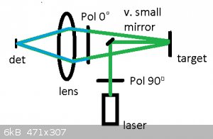
No idea if the Raman light will be blocked as well as the laser light.
Edit:
Perhaps rotate both Pol filters keeping them exactly 90<sup>o</sup> to each other while running an integration would be interesting.
[Edited on 27-3-2016 by aga]
|
|
|
Metacelsus
International Hazard
Posts: 2531
Registered: 26-12-2012
Location: Boston, MA
Member Is Offline
Mood: Double, double, toil and trouble
|
|
Quote: Originally posted by aga  | | Has anyone worked out how to cut out the excitation laser without an expensive notch filter yet ? |
Edge filters work if you only want to observe either Stokes or Anti-Stokes light. I used a colored-glass edge filter in my attempt to build a Raman
spectroscope, but I got what I paid $25 for (aka: it still let a lot of laser light through). I eventually added a thin strip of electrical tape in
front of the detector to physically block the laser light.
Edit:
Aga, where's your diffraction grating in that setup? Or does "det" just mean "spectroscope entrance slit", and not the actual CCD?
[Edited on 3-27-2016 by Metacelsus]
|
|
|
m1tanker78
National Hazard
Posts: 685
Registered: 5-1-2011
Member Is Offline
Mood: No Mood
|
|
Aga, you bring up a good point. Some of my early experiments showed that a pol filter blocked probably > 90% of the incident and reflected laser
light. Most of the Rayleigh scattered light (and presumably Raman) passes the filter regardless of filter angle. This, combined with a colored
solution 'filter' allowed me to observe green light coming from a red laser. I'll dig out the pol filters and see how they fare in place of the dichro
filters I have now. There's still the need to kill the Rayleigh light but attenuating the reflected laser light from the cuvette/vial may relax the
downstream filter requirements.
Metacelsus, Did the electrical tape cause ghosting or any other ill effects? Was it notch or edge? Currently, I would need a ~208 micron-wide strip of
tape in order to notch out 2nm of laser bandwidth. 
Chemical CURIOSITY KILLED THE CATalyst.
|
|
|
aga
Forum Drunkard
Posts: 7030
Registered: 25-3-2014
Member Is Offline
|
|
| Quote: Originally posted by Metacelsus | | where's your diffraction grating in that setup? Or does "det" just mean "spectroscope entrance slit", and not the actual CCD? |
Yes, that's just the 'front end' to try to get rid of as much laser light as possible.
'det' is just the entrance the spectroscope.
|
|
|
m1tanker78
National Hazard
Posts: 685
Registered: 5-1-2011
Member Is Offline
Mood: No Mood
|
|
I finally dismantled and subdued the inside of the prototype enclosure and all of the fixtures. While reassembling everything, I took the opportunity
to insert some polarizers along the different paths only to discover that the cleanup filter effectively scrambles the laser polarization. The idea
was to try and block much of the reflected laser light (from the cuvette / solid object) by inserting a polarizer rotated 90* to the laser plane.
I'm not set up for direct laser illumination of the sample so that's the end of that road as far as I'm concerned.
Chemical CURIOSITY KILLED THE CATalyst.
|
|
|
aga
Forum Drunkard
Posts: 7030
Registered: 25-3-2014
Member Is Offline
|
|
Yeah. Right !
It will bug you until you find a solution, or somebody else does.
For me, it simmers there somewhere at the back of my mind and will not go away.
Excitation source > target > detect the Raman spectra.
Sounds simple ... !
Raman did it, so can we, just we don't know how yet.
|
|
|
Marvin
National Hazard
Posts: 995
Registered: 13-10-2002
Member Is Offline
Mood: No Mood
|
|
m1tanker78, The Schott OG550 edge filter can be found pretty cheaply if you want to use a green laser. You might find an edge filter in the same
series for use with a red laser but anti stokes could be a tall order.
|
|
|
m1tanker78
National Hazard
Posts: 685
Registered: 5-1-2011
Member Is Offline
Mood: No Mood
|
|
If 650nm excitation won't produce satisfactory results -- Stokes or anti-Stokes, I will definitely try a different wavelength laser source. It would
be a good idea to have a few of those OG550s on hand.
I took the TCD1304 spectral response graph and annotated the proposed anti-Stokes region of interest. As you can see, the detector shows best response
to light with wavelength from about 450nm up to around 650nm. This was what originally inspired me to try 650nm excitation and capture anti-Stokes.
Whether it works or not is yet to be seen.

I realize that a Raman spec. with red excitation compounded with collecting the weaker anti-Stokes is a very tall order. I'm exhausting my hypothesis
that the TCD1304 may be decently suited for collecting AS Raman when 650nm excitation is used.
| Quote: | | What the actual resolution of your spectrometer will end up being is function of slit width, number of illuminated lines on the grating, and how well
you'll be able to focus the slit onto the CCD (and a lot of complicated stuff related to the abberations present in the design of your particular
spectrograph). And if you find a way to quantify this I would love to hear
|
That's a lot of ground to cover and no, I haven't got that all figured out yet. 
Chemical CURIOSITY KILLED THE CATalyst.
|
|
|
m1tanker78
National Hazard
Posts: 685
Registered: 5-1-2011
Member Is Offline
Mood: No Mood
|
|
Have there been any developments lately? Marvin, did your TCD's arrive in good working condition? tvaettbjoern, last
I read you were waiting for a PCB. Any progress?
Along those lines... What ever happened to the OP (ragadast) and others who were designing a Raman spec? Seems like ragadast, smeard and others just
fell off the map. Should the rest of us hire bodyguards or what?? 
I came across a guy who says he can machine some of the assemblies I need for the project. More than anything, I'm waiting for him to make the laser
assembly box and an adjustable mirror mount. I reluctantly gave him the go-ahead on those two items -- I'll be thrilled if he does good work.
In the meantime, I ordered a bunch of gas discharge bulbs of different gas compositions to add to the spectral calibration regiment. I'm not so sure
that I want HV around the spectrometer so I won't be drilling holes for these bulbs just yet...
I dug out the Edmund filters to verify their performance. I was concerned about the published data that Edmund has on these filters. Not that I had
any specific reason to doubt; just that manufacturers sometimes publish optimistic data. I used the good ol' fluorescent work light and
recorded calibration spectra. I then used a halogen bulb to produce broader and more intense illumination and inserted one of the Edmund filters in
the light path. The highlighted area in the graph shows (roughly) the blocking region of the filter that falls between about 10-90% of maximum
transmittance.
Judging by the calibration curve (using widely published data of phosphors), the 10/90 transition occurs over about 5nm (125 cm-1). Looking at the
published Raman spectra of typical stuff I'd be measuring for verification (such as toluene, sulfur, etc...), there doesn't seem to be much (if any)
useful data below ~150 cm-1. At higher laser power I may need to chain two of these filters to achieve good optical density.
I incorrectly posted before about the filter angle of incidence being 45*. The normative AOI is in fact 0* -- as claimed in the published data and the
packaging they came in. I tilted the filter about 2 or 3* to move the blocking region to a location (relative to the calibration spectrum) that will
ease measurement of the transition band.
Calibration curve is green, [filtered] halogen curve is red. Graph covers orange and red region of visible spectrum..

Chemical CURIOSITY KILLED THE CATalyst.
|
|
|
tvaettbjoern
Harmless
Posts: 28
Registered: 25-2-2016
Member Is Offline
Mood: No Mood
|
|
Good work with the filters. I'm eager to see anything that can keep me away from the horribly expensive notch filters. As a side note I'm using a
540AELP filter, it may be that the cut-off is just too close to the laser line - I've still not done any real tests.
It's true, lately I've been doing embarrassingly little on the project..
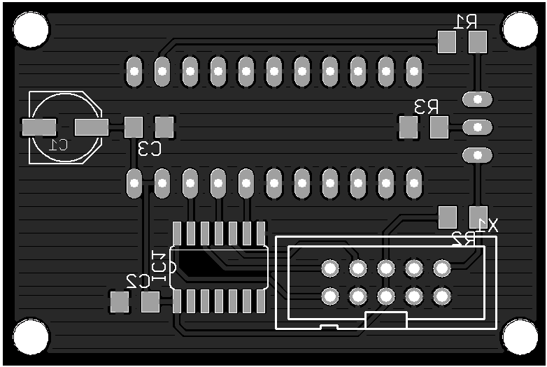
I have received the new PCB (and its replacement) though, and sad to say I see no significant improvement in S/N with any of the two.
Here are the new boards:
1st version with analog signal crossing digital lines:

2nd revision with a little more attention to keeping analog and digital separate:
And here's a photogram of a ruler (you can see the 29 mm-lines of the ruler, and that there are two sources of light in the room):

I the meantime I've also discovered a bug of some sort in the firmware. I get good behaviour almost all the time, but once in while the nucleo board
seems to crash..
|
|
|
aga
Forum Drunkard
Posts: 7030
Registered: 25-3-2014
Member Is Offline
|
|
No success here with getting rid of the excitation laser without an expensive notch filter.
One idea was to pulse the light so that sampling only happened when the laser was Off.
Some reading suggests that femtoseconds are involved, which are a bit out of reach.
Another idea is to use an optical delay system to bring switching into the realm of current microprocessors (~125ns instruction time).
Considered two mirrors with an input angle of 89.9 degrees and calculated 0.382 ns delay per mm of mirror.
Then considered a box arrangement with 4 mirrors:

With each mirror being of equal length and with an incident angle of 44.9 degrees this gives a calculated delay of 1.342ns per mm of mirror.
This arrangement is basically 2D, so if the mirrors were 100mm square, configured in a 3D box, the exit beam could be fed back in a few mm higher up,
giving double the delay.
If separators between each beam channel were 2mm thick and the beam space also 2mm, with 4x 100mm square mirrors, this calculates to give a maximum
total path of 644metres = total delay of 2147ns, = 17 cpu instruction cycles which could be useful.
This all depends on the trig calcs being correct :
Attachment: delay calcs.xlsx (15kB)
This file has been downloaded 416 times
The calculations are for the length of the Green line (first circuit) and to figure out q so the number of circuits could be calculated. The circuit
length is the same for each iteration.
|
|
|
Marvin
National Hazard
Posts: 995
Registered: 13-10-2002
Member Is Offline
Mood: No Mood
|
|
An easy way to tell if a filter is going to reject the laser line well is to point the beam at some skin or some fabric and just hold the filter in
front of your eye and look at the spot (not at the beam!!!). If the dot looks orange it stands a good chance of working. In the case of the things I
pointed the beam at, it was probably fluorescence rather than Raman, but it did look orange. The fact the filter looks orange does not make this any
less of a test.
The sequence of events was, my CCDs arrived, I found my discovery board, completely failed to compile the tools for my netbook but turned out that it
was available as a package through apt-get. I compiled a program to blink an LED and started tweaking, moving it from a flash to RAM allowing it to
be soft loaded and debugged through the link interface (I have a reason for wanting this) and learning about core coupled memory.
Then I caught a nasty cold virus which ate up a lot of my energy for several weeks and knocked my concentration away from Raman. While I was getting
better the hackaday prize started again this year and rather than cheer lead someone else and be largely ignored I want to enter something (and
probably be largely ignored). Raman has been 'done' on hackaday, and did 'well', so it isn't an option for me. My entry isn't epic and it doesn't
'matter' so it won't win but if I find a few people that get what I'm trying to do that would be cool. I also get to stop kicking myself wondering
what would have happened.
Right now I'm getting too little done much too slowly. I'll put together a few bits for Raman together when I start using the discovery for my new
project. I still have no idea how I'm going to mount the optics for Raman or what I'll use for a beam splitter. I'll probably use 90 degree
illumination for testing. When I check thorlabs or edmund they want a heavy chunk of cash just for a lens that launches light into a fibre and those
aren't even achromatic. I check ebay occasionally and haven't found anything better. I've bought an 80x objective lens but the inside lens is very
narrow.
In short, all at sea and my attention is divided.
|
|
|
m1tanker78
National Hazard
Posts: 685
Registered: 5-1-2011
Member Is Offline
Mood: No Mood
|
|
| Quote: Originally posted by tvaettbjoern | | As a side note I'm using a 540AELP filter, it may be that the cut-off is just too close to the laser line - I've still not done any real tests.
|
It seems that increasing the AOI red-shifts the cutoff. You're right, that filter may not cut it for 532nm illumination. If the laser wavelength and
filter cutoff were a little closer, it may be possible to take the reflected light from the filter rather than the transmitted light. Someone
out there is bound to have a more suitable filter and be willing to part from it for a reasonable price. Good deals pop up on ebay from time to time.
I'm not so sure about optical delays. It would certainly make for an interesting set of experiments. Seems it would be difficult to do in an amateur
setting but who knows..?
I have a few ideas for laser light rejection that haven't materialized yet. They live in my mind and some in a CAD program. I happen to have several
short-pass filters on hand so I'm working with what I have.
Chemical CURIOSITY KILLED THE CATalyst.
|
|
|
Marvin
National Hazard
Posts: 995
Registered: 13-10-2002
Member Is Offline
Mood: No Mood
|
|
The 540AELP is the real deal. It's intended for Raman with a 532nm laser and is specced to have something like OD5 at the laser line.
bjomejag (omega optical) ran out not long after I bought mine, but he has more on ebay and they are a fraction of the price you'd normally have to pay
for this quality of filter.
The Schott OG550 is useful and it's cheaper, but it obscures some of the spectrum we'd be interested in.
|
|
|
Metacelsus
International Hazard
Posts: 2531
Registered: 26-12-2012
Location: Boston, MA
Member Is Offline
Mood: Double, double, toil and trouble
|
|
| Quote: Originally posted by Marvin |
bjomejag (omega optical) ran out not long after I bought mine, but he has more on ebay and they are a fraction of the price you'd normally have to pay
for this quality of filter. |
I just bought one. $39.50 + $5 shipping is an astoundingly low price (and I still have those other parts for the spectroscope lying around).
|
|
|
m1tanker78
National Hazard
Posts: 685
Registered: 5-1-2011
Member Is Offline
Mood: No Mood
|
|
That definitely puts the 'cheap' in cheap Raman spectroscopy. OD5 is very good for a single piece.
I was looking at those ebay postings yesterday but the description seemed contradictory...
| Quote: | | The filter is designed to pass the Emission of a 532nm laser; yet to attenuate to1x10e6 the laser as well as the entire spectrum from
the UV to the 530nm. |
It's probably just a typo. Also beware that the description is apparently copy/pasted from a 50mm diameter listing. Pay attention to the item title,
not the description, for the correct diameter.
Chemical CURIOSITY KILLED THE CATalyst.
|
|
|
tvaettbjoern
Harmless
Posts: 28
Registered: 25-2-2016
Member Is Offline
Mood: No Mood
|
|
I've done a few tests with an electrolumiscent/fluorescent LCD backlight, and while the laser is attenuated greatly I cannot say if it's adequite for
Raman or if will drown the signal.
If the 540AELP is not good enough, I'll through some money after a thorlabs 550FELH. I don't see a way around a proper interference filter, and it's
still significantly cheaper than a 532nm notch-filter.
|
|
|
m1tanker78
National Hazard
Posts: 685
Registered: 5-1-2011
Member Is Offline
Mood: No Mood
|
|
tvaettbjoern, does your spectrometer design allow you to tune the filter AOI? If so, you'd greatly benefit from recording a few spectra with
increments of the filter AOI. For example, use a tungsten bulb for illumination and record the spectrum with the filter at zero degrees (normal to the
light axis). Increment the filter angle and repeat a few times.
Record a reference spectrum (CFL provides a convenient spread of known peaks/bands).
Optionally, record yet another with the laser on very low power and the filter removed. You may need to temporarily rig something to diffuse the laser
beam. The laser line should not be so luminous as to saturate the detector. This step would help you to see where the laser line falls with respect to
the filter pass/stop band and sort of verify that it is indeed 532nm against the reference spectrum.
Run the spectra over to your favorite image editing software as separate layers. Each layer can be turned on/off and superimposed with various opacity
settings. This will not only characterize the filter, it'll decisively guide you should you need to purchase another filter (hopefully not).
Chemical CURIOSITY KILLED THE CATalyst.
|
|
|
tvaettbjoern
Harmless
Posts: 28
Registered: 25-2-2016
Member Is Offline
Mood: No Mood
|
|
I'm afraid the angle of incidence is locked in the design of my spectrometer. I've basically copied the setup in Mohr's article:

The 540AELP is placed in a short SM1L03 lens tube screwed into the larger SM1L10 lens tube containing a f=25mm spherical lens, that focuses the Raman
scattered light onto the fiber. You can maybe get an idea of it here:

In the photo the lens tube is orthogonal to the microscope objective. I've gone away from this design to eliminate the beamsplitter and the inevitable
loss of light. Instead the laser is now sent through a small 90° prism, in an arrangement very similar to the diagram above. I would rather show a
photo, but apparently I don't have one at hand of the current setup.
In case you're curious, the small filter in front of the beamsplitter is a narrow 2nm band pass filter for 532nm light. However, after investing in a
JDS Uniphase µgreen laser I don't think it's needed anymore..
I would rather buy a new filter than change the above for two (three) reasons:
1. The fiber terminates in a light tight lens tube. I'm not sure I can achieve this with a non-zero angle of incidence.
2. The fiber is situated at the focal point of the spherical lens. Any stray laser light passing the edge-filter can do so only at a non-zero angle
of incidence, and is thus focused somewhere else than on the fiber aperture.
3. I don't have documentation about the 540AELP's transmission characteristics as a function of angle of incidence. (This last bit is partly due to
ignorance and laziness).
Marvin if you know of any good resources for debugging I would love to know. I only took a few classes of the EdX CS50 course, and I never really
became friends with GDB.
|
|
|
Marvin
National Hazard
Posts: 995
Registered: 13-10-2002
Member Is Offline
Mood: No Mood
|
|
I've barely used gdb. I used softice a lot back in the day, and a few embedded toolsets for CPUs that are now irrelevant but I've always had
something better to use. I'm using google as a crib sheet. I don't think I'll need much else beyond load break and memory peek. My original plan
was to write code to connect to the gdb protocol, load, scan the sensor, break and read the result from memory and resume. Avoiding any need for
another CPU. It turns out this is completely unnecessary as there is some support for a virtual com port (according to a hackaday article I read a
while ago and need to chase up).
|
|
|
m1tanker78
National Hazard
Posts: 685
Registered: 5-1-2011
Member Is Offline
Mood: No Mood
|
|
| Quote: Originally posted by tvaettbjoern | I'm afraid the angle of incidence is locked in the design of my spectrometer.
[...]
I would rather buy a new filter than change the above for two (three) reasons:
1. The fiber terminates in a light tight lens tube. I'm not sure I can achieve this with a non-zero angle of incidence.
2. The fiber is situated at the focal point of the spherical lens. Any stray laser light passing the edge-filter can do so only at a non-zero angle
of incidence, and is thus focused somewhere else than on the fiber aperture.
3. I don't have documentation about the 540AELP's transmission characteristics as a function of angle of incidence. (This last bit is partly due to
ignorance and laziness). |
I definitely understand why you wouldn't want to tilt the filter away from normal (zero) however, I think that most manufacturers intentionally coat
the optics so that the end user will have to tilt the filter slightly in order to fine tune the cutoff. This gives both the manufacturer and the end
user a little bit of leeway. It also has the advantage of shifting reflections away from the optical axis (presumably the end user will use a damper
of some sort).
I had to completely redesign the filter housing a few times. It went from light-tight zero to light-tight 45 to questionable revolving door. Once I
establish what the 'magic angle' is, I'll probably scrap the revolving door for a fixed housing (maybe with just a tiny bit of adjustment ability).
Right now, that angle hinges -- unintentional pun -- on the new laser's spectral output vs. power which I haven't been able to observe yet.
In response to #3: I couldn't find any direct documentation either. I may have missed something but my own ignorance causes me to wonder why you'd
replace your current filter with one that features 540nm cut-on (against 532nm incident).?.? You'd be throwing away close to 300 cm-1 of Raman
goodness near the laser line, wouldn't you?
EDIT:
tvaettbjoern can you post links to manufacturer's spec's of your current filter as well as the 540 that you're thinking of buying? Some searching on
the Omega site only turned up a '540LP'. Nothing came up under '540AELP'..
[Edited on 5-10-2016 by m1tanker78]
Chemical CURIOSITY KILLED THE CATalyst.
|
|
|
| Pages:
1
..
6
7
8
9
10 |


