| Pages:
1
..
7
8
9
10 |
tvaettbjoern
Harmless

Posts: 28
Registered: 25-2-2016
Member Is Offline
Mood: No Mood
|
|
ah yes I see the benefits.
I'm also not able find the 540AELP, however I also cannot find the 538AELP (or the XR3002, and others I forgot about), but I see them referenced in
papers here and there. But ebay is ebay, and I should run the filter through one of the spectrometers at work to test it myself - even if they only go
to OD3.
I'm guessing, but I don't know, that AELP is Omega's Alpha epsilon long pass filters. Still that doesn't tell me what the transmission at 532nm is.
The only reason I'd go for the Thorlabs 550FELH is if the 540AELP turns out to let too much laser light through. 550nm is some 600cm⁻¹ from the
laser line, so it's even worse, but that or edmund optic's edge filters are the only ones I can find in shops.
When I bought the 540AELP I thought it was reasonably close to the laser line that I'd get as much of the full spectrum I could afford and reasonable
far from 532nm that it'd effectively block the laser. I don't recall having seen a commercial instrument go lower than 150cm⁻¹ - but I never worked
with Raman so I'm not really sure what to expect for the lower limit.
|
|
|
m1tanker78
National Hazard
Posts: 685
Registered: 5-1-2011
Member Is Offline
Mood: No Mood
|
|
I've been working on the project in short spurts here and there. I've managed to make some revisions to the firmware along with some improvements to
the PC interface application. I aligned the laser diode module and all the downstream optics and loaded a cuvette of sulfur powder. I wasn't expecting
to see any Raman peaks right away but I was bewildered by what appeared to be strong fluorescence.
Replacing the sample cuvette with a convex mirror revealed that the laser output is VERY dirty. Some time ago I was conducting some experiments with a
red laser pointer and noticed some orange and green light after the filter. I presented my findings in this thread. What I'm seeing here appears to be the exact same phenomenon but at much higher intensity.
Clearly, the dichroic mirror I'm using for a cleanup filter isn't up to the task of attenuating even the green emission enough to reduce or eliminate
interference with the anti-Stokes Raman signature. The interfering light begins to ramp up around 3000 cm-1 from where the laser line should be. That
and the apparent mode hopping / frequency instability put the bandwidth at a whopping 96*1012 hertz. Yes, that's 96 terahertz if I didn't
goof on a decimal point!
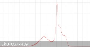
The following spectrograph should put it into better context. It was recorded without the 'cleanup' filter, mirror in place of sample cuvette and a
2-stage short pass filter. The CCD is slightly out of focus and I apparently neglected to record a calibration/reference spectrum.
I'm going to have to design a monochromator and redesign and rebuild the Raman box when time permits. : /
Chemical CURIOSITY KILLED THE CATalyst.
|
|
|
Marvin
National Hazard
Posts: 995
Registered: 13-10-2002
Member Is Offline
Mood: No Mood
|
|
Something is weird, if you point the beam at a DVD, do you get green light along with the spot pattern for red?
Edit,
(Do not look into beam of course, I mean projected onto a wall)
[Edited on 22-8-2016 by Marvin]
|
|
|
m1tanker78
National Hazard
Posts: 685
Registered: 5-1-2011
Member Is Offline
Mood: No Mood
|
|
The out of band light is too weak to project onto the wall or white paper to safely view. With filters in place and laser safety goggles, the errant
emissions can be safely observed by eye and closely follow the graph that I posted up.
I've been playing around with a prism-based monochromator with good results BUT in fact the bulk spectral output of the laser has a wavelength from
656nm to 658nm which is pretty far off from the expected 650nm. If I adjust the monochromator to pass 650nm, the photon flux decreases dramatically.
As a result, I have to bump the detector integration time high enough that the dark noise dominates and saturates the detector! I'm talking seconds
here, not minutes. Not surprising, the filters do a superb job of blocking the laser light when they aren't irradiated with < 650nm red light.
I'm in the process of implementing active cooling for the detector. That should drastically reduce dark noise but I have some serious challenges with
condensation and frost buildup. I could probably forgo the cooling with a good stable laser but don't want to gamble on it just yet.
I've also toyed with blocking the laser line (actually, the line and everything below it in wavelength) by physically masking it but the results were
very bad and I gave up quick. There are 2 major problems with doing this. First, all the materials I tried create way too much stray light inside the
camera. Second, the focal plane of the spectrum lies below the CCD glass -- the detector elements are somewhat recessed under the cover
glass. The problem is exacerbated with short focal length optics.
External stabilization of the laser has been on my mind but I lack the real estate inside the box to experiment with it. That would present another
set of optics that would need to be tweaked. That is, another set of opportunities for error.
[Edited on 8-25-2016 by m1tanker78]
Chemical CURIOSITY KILLED THE CATalyst.
|
|
|
Marvin
National Hazard
Posts: 995
Registered: 13-10-2002
Member Is Offline
Mood: No Mood
|
|
Is the spectrum you posted massively massively overexposed? There is more OOB than laser line.
What is the spectral width of your monochromator?
I think cooling the CCD invites a lot of problems, I plan to wait for a much later iteration. I've just taken delivery of some more sensors, but I
need to test them. I have had no spare time/energy over the past few months and still don't but I'm hoping things will ease up in a week or so.
|
|
|
m1tanker78
National Hazard
Posts: 685
Registered: 5-1-2011
Member Is Offline
Mood: No Mood
|
|
Marvin, the shots weren't overexposed. The laser line was greatly attenuated with 2 filters. That's why the OOB stuff appears to have a large
magnitude compared to the laser. It inconveniently crops up right smack where the anti-Stokes Raman band should be and washes it out (I think).
The spectral width of the monochromator is variable. It depends on slit width and how much the beam is allowed to disperse. It's a temporary measure
while I figure out what to do about the laser troubles.
Chilling the CCD isn't trivial but would be great to have for a desktop or 'briefcase' unit. I'm almost certain I'd be observing anti-Stokes right now
if I could chill the hell out of the detector. It doesn't get to the root of the problem but it would certainly justify the need for a better laser.
[Edited on 8-25-2016 by m1tanker78]
Chemical CURIOSITY KILLED THE CATalyst.
|
|
|
m1tanker78
National Hazard
Posts: 685
Registered: 5-1-2011
Member Is Offline
Mood: No Mood
|
|
I've completed the circuit, firmware and software for the laser power control. No more tweaking a noisy potentiometer to limit the laser current.
The software now accepts inputs for calibration peaks of a spectrum/spectra and calculates absolute wavelength on the array. With that, it's now
possible to set the laser line location and the software will calculate the relative wavenumber offset for each point. No longer do I have to
guesstimate (against a calibration spectrum) the wavelength of a peak or go punch-happy with the calculator to figure out the wavenumber offset. I
have to work out some minor non-linearities of the grating and so on.
With this, I've been able to observe the wavelength of the laser peak at different current steps. Below the lasing threshold, the LD behaves much like
a typical red LED. When the threshold is reached, the LD peaks at just under 651nm. From there, the peak wavelength is almost proportional to the
current up to just over 661nm where the safe operating current limit is reached.
Note that the laser line doesn't simply red-shift when the current is increased. The line actually broadens toward the red as does the peak. Also note
that the sensor exposure time must be decreased as the LD current is increased.
I can't yet say if it's a current dependence or thermal dependence (probably the same). That's got me thinking that investing first in temp. control
over the laser might be more immediately prudent than cooling the CCD.
Now that I can precisely control the LD current, I did a quick bench-top test of ECDL and sure enough, feeding a band-limited beam back to the laser
will cause it to 'lase' when it's below its natural lasing threshold. I haven't yet gleaned anything else from the experiment. : \
Chemical CURIOSITY KILLED THE CATalyst.
|
|
|
tvaettbjoern
Harmless
Posts: 28
Registered: 25-2-2016
Member Is Offline
Mood: No Mood
|
|
Good work.
About a year ago I read a little up on lasers and reached the conclusion that it would be cheaper (and a lot easier) to buy a used lab-laser than
building a monochromator or an ECDL-module. So I took the lazy approach and found a used metrological green laser on ebay.
One thing I can say about the µgreen laser I have is that there's /tight/ temperature control.
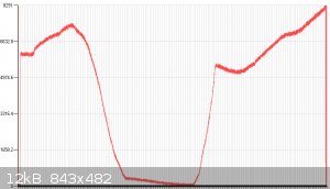
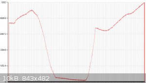
On a separate note I ran the 540AELP Raman-filter through a spectrometer at work and it appears to cut emission efficiently from 531 nm and below. A
picture speaks louder than words so:
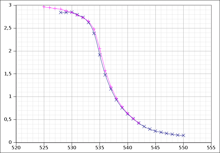
(the two curves represent the same measurements but with different calibrations)
From this it would appear that the filter is unsuitable for Raman with excitation at 532nm, but the spectrometer I used has a bandwidth of 8nm (so
much for a precise measurement) and has only a single-grating monochromator, so any measurements above 2 are inherently unreliable.
[Edited on 6-9-2016 by tvaettbjoern]
|
|
|
Marvin
National Hazard
Posts: 995
Registered: 13-10-2002
Member Is Offline
Mood: No Mood
|
|
tvaettbjoern,
Is that an OD plot?
If so it looks fine for Raman with 532nm.
|
|
|
tvaettbjoern
Harmless
Posts: 28
Registered: 25-2-2016
Member Is Offline
Mood: No Mood
|
|
Yes that's exactly what it is, I forgot to put titles on my axes..
Yes I think so too. I was expecting higher OD below 535 nm, but I'm guessing it was too much to expect from my school's spectrometer to be able to
accurately measure the very steep slope of an edge-filter.
|
|
|
Marvin
National Hazard
Posts: 995
Registered: 13-10-2002
Member Is Offline
Mood: No Mood
|
|
You may find you have some light bleed round the edges. Bandwidth should not affect the OD plateau much. Cool you have access to hardware that will
do that.
|
|
|
m1tanker78
National Hazard
Posts: 685
Registered: 5-1-2011
Member Is Offline
Mood: No Mood
|
|
Would you happen to know what that temperature is? Will the temp control compensate when you increase or decrease the laser power? I should have done
more research earlier on about the typical laser diodes that are available out there and how temperature greatly influences their characteristics.
Hindsight...
From the limited research I've done, it seems I wouldn't need to cool the laser down all that much to keep it at 650nm at a reasonable output. Still,
it's a hassle sealing it in a dry fixture and preventing condensation and so on. If I come across a reasonably priced stabilized laser, I may end up
cheating a little too.
| Quote: | | From this it would appear that the filter is unsuitable for Raman with excitation at 532nm, but the spectrometer I used has a bandwidth of 8nm (so
much for a precise measurement) and has only a single-grating monochromator, so any measurements above 2 are inherently unreliable.
|
The filter OD might be a little on the weak side. Pop the filter into the Raman box and see what sort of exposure time you can push with something
white in place of the sample cuvette (or a white powder sample in a cuvette). With some luck, you may even be pleasantly surprised with a Raman
fingerprint. 
Chemical CURIOSITY KILLED THE CATalyst.
|
|
|
tvaettbjoern
Harmless
Posts: 28
Registered: 25-2-2016
Member Is Offline
Mood: No Mood
|
|
Marvin: Yes, I guess the bandwidth becomes insignificant when measuring far (10 nm?) from the slope. I'm inclined to think it's stray light from
inside the monochromator that's keeping the OD lower than the expected value of 5 (which the spectrometer can't even read anyway)
m1tanker: I don't know exactly how jds uniphase maintains single frequency operation in their µgreen lasers, but on Sam's LaserFAQ you can find
pictures of the insides of several versions the laser. They're all built on-top of one (or two) TECs controlling not only the temperature of the pump
diode but also the Nd:YVO₄ and the KDP-crystal (and, I suspect, maintain a constant length of the laser cavity). I can't remember where I read this,
but I recall having seen that the temperature control is ±0.01°C and there's a nice big sheet of Iridium-foil between the laser head and its
heatsink. Besides the temperature control, there's also an optical feedback system, but I think that's for maintaining a constant output power.
I haven't played much with the laser. It's set to 10 mW, a value I'm happy with so far.
I think it's really cool you're constructing you're own laser. I know some universities have construction of ECDLs as lab exercises, so it's a doable
task. Like I said, I gave up before even starting, thinking there's too much I don't know about lasers :p
|
|
|
m1tanker78
National Hazard
Posts: 685
Registered: 5-1-2011
Member Is Offline
Mood: No Mood
|
|
Thanks Esben. I found one of the pages you refer to on Sam's Laser FAQ where there are several pinouts of various models of the JDSU. I see that in
addition to the LD and TEC pins there are two thermistors and a photodiode (for optical feedback). It's an interesting read and provides some
inspiration for how to go about building a thermally stabilized 650nm laser head, should there be a need.
I'm not as concerned with mode stability as I am having the ability to 'walk' the bulk laser line to a specific wavelength and keep it there for some
time for a given power output. The specific wavelength would be governed by the cleanup filter/monochromator(s) and the laser line filter(s). I hope
to overcome the monochromator losses by cranking up the laser power.
I tip my hat to the people who do this stuff for a living!
Chemical CURIOSITY KILLED THE CATalyst.
|
|
|
aga
Forum Drunkard
Posts: 7030
Registered: 25-3-2014
Member Is Offline
|
|
Has anyone found any specific details about Raman's original work ?
I never have seen a detailed paper (if it exists), although ISTR that in one report he used Sunlight for the beam that did the exciting of the
substance under test.
Hardly likely that lasers were widely available back in 1928.
If he did use Sunlight, no notch filter would work, as the light is basically pan-spectrum, so perhaps we've been barking up the wrong tree all this
time.
In an effort to find out, a source of concentrated sunlight would be useful.
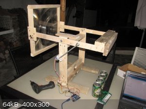
Plastic Fresnel lens from ebay, about 15" square, some old pallets, plus an arduino, steppers and a big steel bearing.
Burns stuff and boils small amounts of water even with rough manual alignment.
Needs finishing = upgrade the stepper motors & complete the arduino code, also modifying to at least get the focal point to the right place (4"
too far forwards at the mo) and then figure out how Raman did his thing.
This Raman tech is far too important for us to just forget.
If it can possibly be had, never more will we have to ask questions like 'What did i just make ?'.
Funny how one word on a TODO list can remain undone for such a long time.
Got too many like that on the list !
|
|
|
tvaettbjoern
Harmless
Posts: 28
Registered: 25-2-2016
Member Is Offline
Mood: No Mood
|
|
not forgetting, just busy with the work actually pays the rent :/
In Raman's Nobel lecture ( http://www.nobelprize.org/nobel_prizes/physics/laureates/193... ) you'll see the effect was first observed with sunlight, but once they got down
to the "real" investigation of the effect they used mercury arc lamps and filters.
The original paper from 1928 is available here: https://www.thevespiary.org/library/Files_Uploaded_by_Users/...
|
|
|
aga
Forum Drunkard
Posts: 7030
Registered: 25-3-2014
Member Is Offline
|
|
This article was interesting : https://www.acs.org/content/acs/en/education/whatischemistry...
There's a diagram showing one colour filter on the Input (to get 1 wavelength) then 1 other coloured filter on the output showed the effect.
This sounds like a simpler way than attempting to grab the entire spectral responses all in one go, then by switching the input filter/wavelength,
other spectra could be observed.
From the little bits of info gleaned so far, the input energy has to be quite High to get an observable effect by eye, hence using sunlight.
My little laser pointers can't melt rocks. This bit of rock was used to find out if the geometry was right for keeping the same focus point all the
time on the solar rig :-

Those black bits are Glassy. The rock behind it is fresh one of the same type.
Need the welding mask to be able to align it 'cos the focussed light is so intensely bright.
Needless to say, using focussed sunlight is rather a dangerous thing to do, but then, so is using lasers.
|
|
|
m1tanker78
National Hazard
Posts: 685
Registered: 5-1-2011
Member Is Offline
Mood: No Mood
|
|
aga, have you done any calculations on how much optical power you'd have at your disposal after filtering out all but your desired wavelength from a
beam of sunlight? A spectrally castigated incident beam may well be equal to or less than a decent laser unless you can collect a large swath of
sunlight, focus, filter and efficiently dump all the unwanted spectral content. Raman's filtered sunlight was probably fairly broadband which is how
he was able to observe the 'errant' spectral lines.
Almost a century later, Raman's discoveries still inspire people to give it a try and affords much room to grow as technologies emerge or mature.
I've had no shortage of paying work and I'm afraid I don't even remember where the hell I left off with the project. I'm anxious to jump back in and
make some progress when things ease up a little.
Chemical CURIOSITY KILLED THE CATalyst.
|
|
|
m1tanker78
National Hazard
Posts: 685
Registered: 5-1-2011
Member Is Offline
Mood: No Mood
|
|
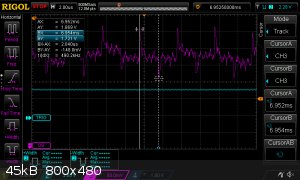
The odd/even pixel differential is easily observed in this scope capture. The datasheet defines this as 'register imbalance'. Interestingly, each step
of 'M' also causes a small blip (four steps of the M clock per pixel read out). The peak-to-peak difference is about 150mV which equates to 5-10% of
the rail-to-rail video output. Each pixel read out spans about 2µS when M is clocked at 2MHz. Photo response non-uniformity (PRNU @ datasheet) is
also observed in the scope capture although the CCD was evenly illuminated at near saturation -- not 50% like the datasheet defines.
Unfortunately, the TCD1304 has a single OS output rather than one output for odd and another for even pixels like the TCD1705. The register imbalance
should be fairly constant across the entire frame which makes for easy mathing away. The PRNU varies from chip to chip and involves a bit more work to
devise and math away. The good news is that PRNU should remain fairly constant for a given CCD chip -- a fingerprint of sorts. Once stored, it can be
applied to each scan to correct the PRNU for that particular CCD.
Chemical CURIOSITY KILLED THE CATalyst.
|
|
|
tvaettbjoern
Harmless
Posts: 28
Registered: 25-2-2016
Member Is Offline
Mood: No Mood
|
|
Interesting. I never looked /that/ close at the data. My understanding of how ADCs work is not particularly strong, but won't the ADC deliver the
average of what it measures during the sampling time?
If the peak-to-peak difference is a problem can't you just sample for say 1.0 µs and time the triggering of the ADC to be halfway between two peaks?
I know you use an FPGA, and I have absolutely no idea how they work, so maybe I'm getting it all wrong.. With the ARM processor I use I can shift the
timer that triggers the ADC in steps of 0.5 µs (even finer if I start fiddling with the timer counter register).
|
|
|
m1tanker78
National Hazard
Posts: 685
Registered: 5-1-2011
Member Is Offline
Mood: No Mood
|
|
Yes, an ADC will average out a signal during the sampling period. The problem arises when there is artificial, for lack of a better term, and constant
variations. I can adjust the sampling window trigger point and duration in ~2.5nS increments. I'm puzzled by the fact that excluding the first 25% or
so of the pixel readout period doesn't seem to improve the register imbalance. As expected, the dynamic range suffers as a result of closing the
sampling window.
Even subtle periodic variations are problematic because they grow in proportion to the number of exposures that are integrated. Averaging across
pixels solves the problem but introduces a new problem -- valid information is masked or lost. On the other hand, applying a correction algorithm to
each exposure is much more desirable in order to maintain signal integrity.
The smaller peaks on the output that correspond to the M clock are all positive-going and roughly the same amplitude per given pixel. In this case,
the ADC dutifully averages them out.
Chemical CURIOSITY KILLED THE CATalyst.
|
|
|
m1tanker78
National Hazard
Posts: 685
Registered: 5-1-2011
Member Is Offline
Mood: No Mood
|
|
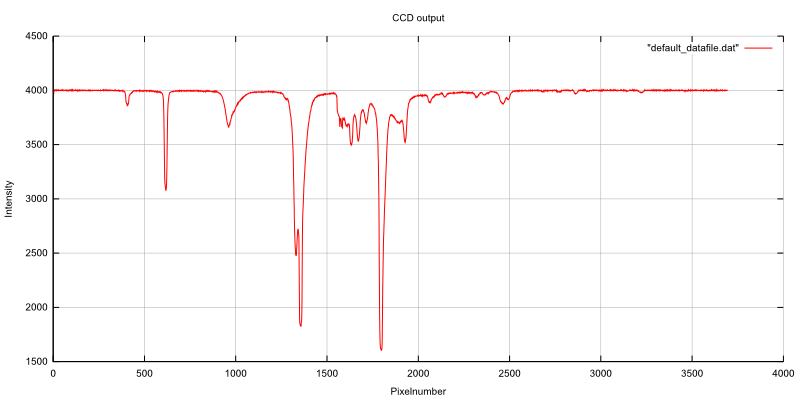
I got around to implementing a correction scheme for the CCD register imbalance. The PC software can derive the correct factor and whether it should
be applied to the odd or even pixel values. Additionally, the factor can be derived by trial and error. Either way, it's stored and (optionally)
applied to subsequent exposures.
Again, the register imbalance is fairly constant for a given CCD chip. There should be no need to change the factor unless the CCD is swapped out or
something partially 'fries' one of the output amplifier stages. The system has been put through its paces for 3 days straight -- taking exposure after
exposure and offloading to the PC. So far, the register imbalance parameters are still the same as when they were first derived.
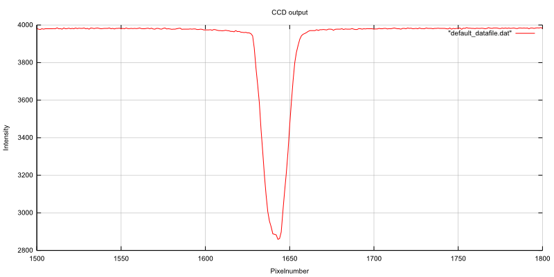
The correction scheme preserves all valid information while smoothing out the differences introduced by minute manufacturing inconsistencies
between the CCD's two output stages. I recorded two exposures to illustrate the difference the scheme makes. Both exposures were taken with a pencil
leaned up on the CCD and wire shadows. Exposure time and all else is equal:
Raw exposure:
Corrected exposure:
Chemical CURIOSITY KILLED THE CATalyst.
|
|
|
tvaettbjoern
Harmless
Posts: 28
Registered: 25-2-2016
Member Is Offline
Mood: No Mood
|
|
That is certainly a very tangible improvement. I should look more into this myself..
Your CCD's register imbalance is quite large. I don't think I've seen that big a difference in any of my recordings. Here's a couple of readings I did
with a simple 3D-printed spectrometer:
CFL lamp
Na-spectral lamp (doublet at 589nm)
I realize the scaling of the axes is not quite the same, but still.
|
|
|
m1tanker78
National Hazard
Posts: 685
Registered: 5-1-2011
Member Is Offline
Mood: No Mood
|
|
That's odd. Looking at one of your oscilloscope captures of OS, it looks as though there is close to a half volt swing between odd and even pixels.
Assuming you aren't averaging or filtering in software, I'd guess that your ADC is geared to suppress noise and possibly sharp transients..?
Are there any passive components external to the ADC? Can you post a link to the ADC datasheet?
========================
The next logical step from reg. imbalance correction is determining and correcting for PRNU. I added the ability to record dark exposures and correct
for the same a few firmware revisions back. PRNU will require a built-in light source that can evenly illuminate the CCD. I basically have the
skeleton but not the light. Heck, I don't even have a proper box nor working laser at the moment. Speaking of lasers, I've ordered a 532nm laser ..
yeah, going green (but I'll still prototype with 650nm and push that to the limit).
I know for a fact that the CCD that I'm working with now has at least three 'hot pixels'. They manifest when I record longer dark exposures. These
will also need to be accounted for.
I added a programmable test port that can trigger an oscilloscope or logic analyzer at any state of any of the several state machines on the FPGA.
I'm building some small metal boxes to house the various peripherals of the system. All interconnects will be coaxial cable with SMA connectors. That
should eliminate much of the parasitic noise and crosstalk.
The firmware and PC software become increasingly robust with each push. Now the optics need to catch up! 
Chemical CURIOSITY KILLED THE CATalyst.
|
|
|
tvaettbjoern
Harmless
Posts: 28
Registered: 25-2-2016
Member Is Offline
Mood: No Mood
|
|
I'm using the stm32f401's built-in ADC. As far as I can see in the manual for the nucleo board, there's nothing between the ADC and the physical pin I connect OS to.
The datasheet and the reference manual don't mention anything specific with regards to noise-suppression and or sharp transients, so I always attributed the noise you
see on the scope-captures to come from the scope.
I also see hot pixels, but whenever the I have integration times of longer than 1s, everything drowns in dark current (just as the datasheet says), so
inspired by the audine camera I've made new PCBs with cut-outs for a cold-tip, and with signal conditioning (circuit stolen from David Allmon), but I'm still waiting for them to arrive.
What laser did you get?
[Edited on 4-3-2017 by tvaettbjoern]
|
|
|
| Pages:
1
..
7
8
9
10 |


