| Pages:
1
2
3
4
5
6
..
11 |
Hennig Brand
International Hazard

Posts: 1284
Registered: 7-6-2009
Member Is Offline
Mood: No Mood
|
|
Don't worry about it, it is an entertaining video anyway.
"A risk-free world is a very dull world, one from which we are apt to learn little of consequence." -Geerat Vermeij
|
|
|
ecos
Hazard to Others
Posts: 464
Registered: 6-3-2014
Member Is Offline
Mood: Learning !
|
|
I have a friend who lost his hand because of mobile phone !
he made similar setup but he received an advertisement sms while the wires were connected to detonator !
another one made similar setup and when he turned on the phone it played the startup tone and he was severely injured.
avoid such mobile phones setup ! really risky.
|
|
|
jock88
National Hazard
Posts: 505
Registered: 13-12-2012
Member Is Offline
Mood: No Mood
|
|
Also the mother in law may send you a text at the appropriate time if she knows what you are up to.
You would need to put a tone decoder (dual tone would be better) on the output of the phone set it up so that pressing the (say) 4 will give an output
at the other end.
|
|
|
Hennig Brand
International Hazard
Posts: 1284
Registered: 7-6-2009
Member Is Offline
Mood: No Mood
|
|
Tone encoding works well, I made a radio controlled switch from a pair of GMRS radios a few years back. The receiver had a tone decoder and also a
timer which when activated disconnected the output to the igniter for a minute or so allowing time to safely make connections and retire to a safe
distance before the system became active (I suppose the timer could have also disconnected the input to the encoder from the radio receiver). The tone
generator at the transmitter was an mp3 player. The tones were made with a computer tone generator program and then saved as an mp3 file and put on a
free mp3 player (someone got it for subscribing to something IIRC, very cheap mp3 player). The system could be used with any audio transmitter
receiver pair. I built it just for fun, and other than a few tests I have always used wires or fuse when doing any serious blasting (wires are best).
Regarding controlling an EBW fireset, the system could be charged and fired from a single control. One control could charge the capacitor bank and
fire it. A comparator could be used to automatically fire the EBW when the voltage of the capacitor bank rose to a set value. A suitably low
proportional voltage could be made available for the comparator using a voltage divider. When the voltage rose above the set point and the comparator
changed state it could send the trigger pulse to the trigatron and fire the EBW.
[Edited on 15-5-2015 by Hennig Brand]
"A risk-free world is a very dull world, one from which we are apt to learn little of consequence." -Geerat Vermeij
|
|
|
Varmint
Hazard to Others
Posts: 264
Registered: 30-5-2013
Location: Near Atlanta, GA
Member Is Offline
Mood: No Mood
|
|
The wise engineer would make it a pass-key, where a specific sequence is sent, even wiser would be to time encode the key string.
i.e. lets say the pass string is DTMF 27639. The decoded DTMF is sent to a microcontroller and the first 2 chars are expected in 1 second, the 3rd
char 3 to 5 seconds later, the last two characters keyed within one second, sent greater than 3, but less than 5 seconds after the 3rd character.
Bad sequences cause a lockout of a programmed duration, or in fact failsafe the system requiring a physical reset.
Seem complex? Well, you want the largest margin of safety you can engineer, or at least I would if I were working in that area. Bad se
|
|
|
Hennig Brand
International Hazard
Posts: 1284
Registered: 7-6-2009
Member Is Offline
Mood: No Mood
|
|
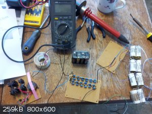
EBW Capacitor Bank Charging Circuit (555 Inverter Based)
Thanks for the radio control encoding tips. I was aware that a lot more sophistication and safety could be added, but to tell the truth I never made
it past using two tones at once. Always meant to go back and make it more sophisticated though. Electricity/electronics is just one of my hobbies, I
went through Chemical Engineering.
First off I will say that Markx was right when he said I needed a beefier power supply than those bug zappers and his suggestion for a circuit was a
good one. The post by Markx earlier in this thread can be found here:
http://www.sciencemadness.org/talk/viewthread.php?tid=23466#...
I have ordered some of the IR2153 and 21531, but they will take a couple of weeks to get to me (paid a lot more for the 21531, oh well live and
learn). In the mean time I have been working on a 555 inverter circuit. The IR2153 is superior as a mosfet driver, but the 555 can be made to work and
it is a much more common IC.
I used the circuit found here:
http://www.eleccircuit.com/220-volts-power-inverter-using-ne...
However, I was not interested in driving a big, heavy, slow 50 or 60Hz transformer or using a voltage multiplier with big capacitors as is required
with such low frequencies. In order to bring the frequency of the astable circuit from 50Hz up to about 15kHz C1 was changed to 1nF, R1 was changed to
1kohm and R2 was changed to 47kohm. This also kept the duty cycle just slightly over 50%. The only part I used that was exactly the same as specified
was the 555 timer IC. I was hesitant to go higher in frequency because I was only using a regular 555, not the faster cmos variety and I was only
using slow 1N4007 diodes not one of the faster types such as UF4007.
The transformer was wound on a plastic bobbin which came with the salvaged pot core used. The ferrite pot core is 3019P, 3C8 material (presently
called 3C81 from what I have read). The primary is 18 turns 26AWG bifular wound in two layers to give a center tap. The secondary was wound in 10
layers, with each layer having about 40 turns of double insulated 40AWG magnet wire. A layer/strip of printer paper just slightly wider than the
bobbin winding surface was wrapped on between each layer which added insulation between layers and also gave a nice flat, smooth, surface to wind on.
There are better commercial insulating papers available for winding. Apparently I had the primary hooked up out of phase yesterday because it took
about 15seconds to even charge the capacitor bank up to 2000V and I was having some trouble with the upper transistor heating, but the heat sinks I
was using yesterday were also tiny and the run times were longer so I am not sure that it is related. Today I changed the transformer primary winding
wiring around and now the circuit charges up the 0.5uF capacitor bank to 4000V in about 5 seconds. I should also mention that there is 40Mohms of
resistance across the capacitor bank as a bleeder and bypass network and that there is 1Mohm (10X 100kohm resistors) between the capacitor bank and
the power supply. So the supply is putting out much more than what would be needed to charge the capacitor bank without these extra loads.
The heat sinks are just what I could find lying around and are not even matched. More than big enough for the 5 second run time though. The pot core
was found on a piece of industrial electronics in a scrap yard. It looks to have been sitting out in the snow and rain for several years. The old
windings were removed before the new windings were put on.
The battery pack I am using is made up of a mix of old AA batteries and so is not ideal. The circuit draws about 0.7-0.8A, from the little battery
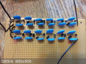
pack, which pulls it down to about 7-7.5Volts. The output from the transformer is about 500-550V which is fed into two six stage half wave voltage
multipliers made up of 3kV 10nF ceramic caps and 1N4007 (1A, 1000V) diodes. The diodes for the two multipliers are run in opposite directions from one
another. The voltage across the two multiplier outputs is greater than 6000V with no load.
 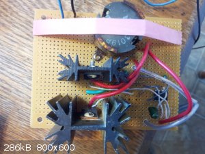 
Found some mounting hardware. It looks a little less amateurish without the pink elastic band. 
[Edited on 15-5-2015 by Hennig Brand]
"A risk-free world is a very dull world, one from which we are apt to learn little of consequence." -Geerat Vermeij
|
|
|
Varmint
Hazard to Others
Posts: 264
Registered: 30-5-2013
Location: Near Atlanta, GA
Member Is Offline
Mood: No Mood
|
|
Henning:
The rectifiers aren't at odds with the chopping frequency, but the conduction to off recovery time.
That's not to say the 1N4007s are inadequate, just that it might require further analysis if your efficiency is below expectation, especially if they
are getting warmer than might be considered normal considering the forward drop vs average current.
|
|
|
Hennig Brand
International Hazard
Posts: 1284
Registered: 7-6-2009
Member Is Offline
Mood: No Mood
|
|
So when it takes them longer to change state, than a faster diode, they dissipate heat and even if it is not enough heat to destroy them it lowers
overall circuit efficiency. I am not yet sure exactly how high a frequency designers would use a regular rectifier diode such as the 1N4007 in a
voltage multiplier circuit. They seem to be working lovely at 15kHz, but 15kHz isn't really all that high as switching supplies go.
Quote: Originally posted by Varmint  | Henning:
The rectifiers aren't at odds with the chopping frequency, but the conduction to off recovery time.
|
I see what you mean, but the amount of times the diode has to change state per unit time is the frequency.
[Edited on 16-5-2015 by Hennig Brand]
"A risk-free world is a very dull world, one from which we are apt to learn little of consequence." -Geerat Vermeij
|
|
|
Hennig Brand
International Hazard
Posts: 1284
Registered: 7-6-2009
Member Is Offline
Mood: No Mood
|
|
Ferrite Transformer & Voltage Multiplier Design Guides
Ferrite Transformer:
Here is a good straightforward method for ferrite transformer design. Also attached is the Magnetics 2013 catalogue with specifications for most
common core sizes and types.
Attachment: Ferrite Transformer & Inductor Design - MagneticsFerritePowerDesign2013.pdf (160kB)
This file has been downloaded 542 times
Attachment: Ferrite Core Specifications - Magnetics2013FerriteCatalog.pdf (1.9MB)
This file has been downloaded 920 times
Ferrite Transformer Design Sample Calculation:
WaAc = (Po * Dcma) / (Kt * Bmax * f)
WaAc = (5W * 500cir.mils/amp) / (0.001 * 2000gauss * 15000Hz)
[used aggressive value for current density since power supply is only run intermittently]
WaAc = 0.0833
From table: 1814 Pot Core is large enough, however, since I had a 3019P core it was used.
Ac = 1.36 cm^2 [3019 effective area value from table]
Np = Vp * 10^8 / (4 * B * Ac * f)
Np = 24V * 10^8 / (4 * 2000 gauss * 1.36 cm^2 * 15000Hz) [12V DC supply voltage, which gives 24V
peak to peak on transformer primary]
Np = 14.71 ---> round up to 15 turns
[Primary is double 15 (30 turns center tapped)]
Ns = Vs / Vp * Np
Ns = 500V / 24V * 15 turns
Ns = 313 turns
Secondary 313 turns
WaAc = 0.0833, Ac = 1.36cm^2
Wa = 0.0833 / 1.36cm^2
Wa = 0.06125
Kwa = NpAwp + NsAws
Wa = 0.06125, K = 0.6 for pot cores, let NpAwp = 1.1NsAws
Aws = (0.6 * 0.06125) / (2.1 * 313)
Aws = 0.000056 cm^2 or 0.0056 mm^2
Secondary: 40 AWG magnet wire
NpAwp = 1.1NsAws
Awp = (1.1 * 313 * 0.000056cm^2) / 15
Awp = 0.00129 cm^2 or 0.129 mm^2
Primary: 26 AWG magnet wire
I used a pot core, but an E core would have been fine too, maybe better in some respects. Also notice that I used a bit more turns than was really
necessary when I wound the transformer above, but it works fine and the extra turns will keep the flux density down even lower. I hadn't done this
calculation when I wound the transformer.
Voltage Multiplier:
Here is a voltage multiplier design guide. I made a small excel sheet, based on a couple of the equations from the guide, which allows quick half wave
multiplier design comparisons to be made. Notice at low frequencies that the capacitors must be much larger in capacitance than at high frequencies.
Notice how above I used 3kV capacitors for the two half wave multipliers made. Even going as low as 1kV caps probably would have been enough, since
the components only need to be rated for the multiplier stage voltage which is about double the supply voltage (supply voltage is ca. 500V in the
above case). Using components rated at least a little higher in value than absolutely needed is good practice though.
Attachment: Voltage Multiplier Design Guide.pdf (289kB)
This file has been downloaded 1201 times
Attachment: Voltage Multiplier Excel Sheet.xlsx (10kB)
This file has been downloaded 564 times
[Edited on 20-5-2015 by Hennig Brand]
"A risk-free world is a very dull world, one from which we are apt to learn little of consequence." -Geerat Vermeij
|
|
|
Hennig Brand
International Hazard
Posts: 1284
Registered: 7-6-2009
Member Is Offline
Mood: No Mood
|
|
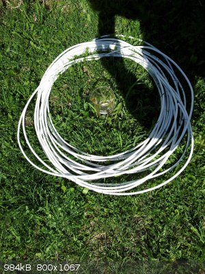
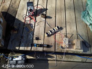
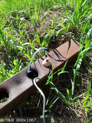
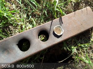
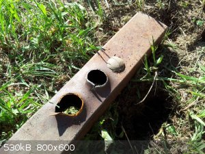
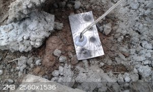
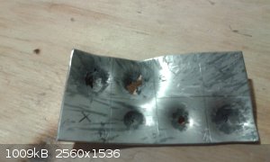
105ft of Blasting Line, 10g of ETN Putty Explosive Initiated With Custom Made ETN EBW Detonator
This test was performed nearly exactly the same as the last test, except that a new homemade power supply was used. The 0.5uF capacitor bank was
charged to ca. 3800V before the homemade brass trigatron was triggered dumping the electrical charge through the blasting cable and bridgewire. The
detonator was made using a 7.6mm id Al casing and 0.7g of ETN; 0.5g was pressed at 100lbs of force, 0.1g was hand pressed and 0.1g was put in nearly
loose. The bridgewire used was 1.5mil diameter copper, about 100mil long. The witness target was 1/8 inch wall thickness square steel tubing. The
blasting cable was made up of 100ft of RG-6 (standard cable, satellite, TV coaxial) and 5-6ft of 18 gauge speaker wire. The main charge was once again
10g of 80% ETN putty explosive.
The test was a complete success. Both 1/8" sides of the steel tubing were perforated in a very brisant detonation.
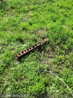
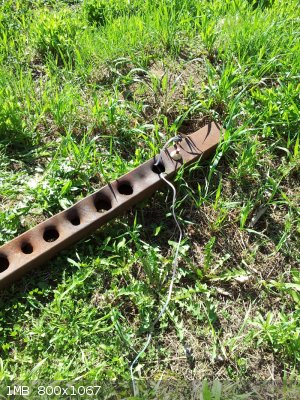
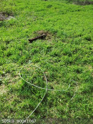
Right now this system is a bit inconvenient because it takes about 15 minutes to set up the modular fireset and run the line to the charge. Once all
fireset components are assembled together permanently in a suitable small enclosure it should only take a couple of minutes to set up.
Being 105ft away is normally far enough for my purposes, but the distance could be doubled to 210ft with the same setup by simply using two 210ft
lengths of the same cable type. Two 210ft pieces in parallel basically have half the inductance and resistance compared to a single cable of the same
length and should perform similarly as a single piece 105ft long. There are also much better cables available, which would allow much longer cable
runs to be made. In my opinion, however, 100ft is enough for most normal small scale blasting. If more distance is needed the blasting box could be
sandbagged 100ft away from the blast and the operator could control the blasting box through long thin cable at a much greater distance away.
I used the old trigatron, in the wooden block, because I wanted to keep everything as much the same as earlier tests as possible.
Here is a current versus time graph generated using the "Distributed Parameter Method" Excel sheet attached earlier in this thread.
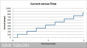
The theoretical numbers for the earlier failed test look better than this test, however the theoretical model assumed fast efficient switching. A
trigatron was used in this successful test, and simple touching of 18 gauge wires was used as the method of switching for the earlier failed test.
Fast efficient switching appears to be very important, but I am unable to quantify it exactly at this time.
For 3800V, 0.5uF, 105ft RG-6, Cu BW 1.5mil D, 100mil L
Current at or above Burst Action = 853 A
Time at or above Burst Action = 1.85 usec
Average rate of Current Rise = 462 A/usec
Trigatron Switching
Detonation Confirmed
For 2400V, 0.67uF, 51ft RG-6, Cu BW 1.5mil D, 100mil L
Current at or above Burst Action = 876 A
Time at or above Burst Action = 1.54 usec
Average rate of Current Rise = 876A/1.54usec = 569 A/usec
Switching accomplished by touching two 18gauge wires together
No detonation from test
[Edited on 22-5-2015 by Hennig Brand]
"A risk-free world is a very dull world, one from which we are apt to learn little of consequence." -Geerat Vermeij
|
|
|
jock88
National Hazard
Posts: 505
Registered: 13-12-2012
Member Is Offline
Mood: No Mood
|
|
How many ebw's could be put in series for a given set up or would you be better off using a bigger cap (same Voltage) and going for parallel?
Would NG be around the same sensitivity as ETN for ebw' detonators?
|
|
|
Hennig Brand
International Hazard
Posts: 1284
Registered: 7-6-2009
Member Is Offline
Mood: No Mood
|
|
These documents give a feel for what is possible with commercial gold EBW detonators. Results would likely be somewhat different with my homemade
copper EBW detonators and fireset. The specs of the capacitors used in the RISI firesets are normally 1uF and 4000V from what I have seen. It looks as
though quite a few commercial detonators can be fired simultaneously in various series parallel configurations depending on cable length, etc.
I have more reading material on series parallel connecting EBWs, but I can't locate it right at the moment.
Attachment: Series Parallel Firing of EBW Detonators.pdf (29kB)
This file has been downloaded 660 times
Attachment: FS-43 Firing System.pdf (35kB)
This file has been downloaded 574 times
Nitroglycerine is a homogenous explosive not well suited to this application, at least not in its pure form. It has very low stable detonation
velocities, while PETN or ETN or MHN, etc, can be initiated low order by an EBW and then quickly accelerate to high order. Progressive increase in
explosive density aids the explosive in accelerating from low order to high order detonation as well, something that would be impossible to do with a
homogenous explosive like NG.
[Edited on 25-5-2015 by Hennig Brand]
"A risk-free world is a very dull world, one from which we are apt to learn little of consequence." -Geerat Vermeij
|
|
|
Hennig Brand
International Hazard
Posts: 1284
Registered: 7-6-2009
Member Is Offline
Mood: No Mood
|
|
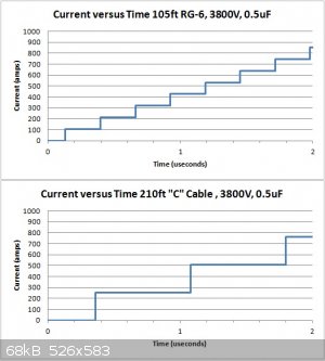
Much Better Cables Are Available
Just did a theoretical comparison between RG-6 coax and the "C" cable sold by RISI using the distributed parameter method. Using "C" cable could
easily double the distance that my system would function effectively, compared to when using RG-6, everything else being equal. I would like to get
some of this cable or something similar.
RG-6 Coaxial
For 3800V, 0.5uF, 105ft RG-6, Cu BW 1.5mil D, 100mil L
Current at or above Burst Action = 853 A
Time at or above Burst Action = 1.85 usec
Average rate of Current Rise = 462 A/usec
Trigatron Switching
Detonation Confirmed
"C" Cable Coaxial
For 3800V, 0.5uF, 210ft RISI "C" Type Coax, Cu BW 1.5mil D, 100mil L
Current at or above Burst Action = 763 A
Time at or above Burst Action = 1.44 usec
Average rate of Current Rise = 531 A/usec
[Edited on 25-5-2015 by Hennig Brand]
"A risk-free world is a very dull world, one from which we are apt to learn little of consequence." -Geerat Vermeij
|
|
|
Hennig Brand
International Hazard
Posts: 1284
Registered: 7-6-2009
Member Is Offline
Mood: No Mood
|
|
| Quote: Originally posted by Hennig Brand | | These documents give a feel for what is possible with commercial gold EBW detonators. Results would likely be somewhat different with my homemade
copper EBW detonators and fireset. The specs of the capacitors used in the RISI firesets are normally 1uF and 4000V from what I have seen. It looks as
though quite a few commercial detonators can be fired simultaneously in various series parallel configurations depending on cable length, etc.
|
What I said about the capacitors in the commercial EBW firesets was kind of misleading I think. More accurately, normally the commercial units I have
seen described have 1uF of capacitance (in total) and are designed to be charged to 4000V. If the capacitor or capacitor bank is designed to be
charged to 4000V it is likely rated for 5000V or more.
"A risk-free world is a very dull world, one from which we are apt to learn little of consequence." -Geerat Vermeij
|
|
|
Hennig Brand
International Hazard
Posts: 1284
Registered: 7-6-2009
Member Is Offline
Mood: No Mood
|
|
I was going from my memory of earlier tests when I wrote down the amount of force used to press the ETN with the lever press. I just checked today and
I am easily pressing with at least 300lbs of force the way I have been doing it. I incorrectly stated that it was only 100lbs of force in several
places in the last couple of pages in this thread. Here are four examples that I found. Any more that state 100lbs of force should also say 300lbs as
well.
First post second line here:
http://www.sciencemadness.org/talk/viewthread.php?tid=23466&...
" A half gram of ETN was pressed in a 7.6mm aluminum casing with over 100lbs of force with a lever press and then another 0.2g was added loose on
top."
It should say "with about 300lbs of force".
Same thing here:
http://www.sciencemadness.org/talk/viewthread.php?tid=23466&...
"About 0.2g was pressed with a lever press at about 100lbs of force, about 0.2g was pressed firmly by hand and about 0.2g was poured in loose and
then only very gently compressed just to settle and remove large voids."
It should say "at about 300lbs of force".
And here:
http://www.sciencemadness.org/talk/viewthread.php?tid=23466&...
"The 7.6mm casing contained about 0.7g of ETN, 0.5g pressed at 100lbs, 0.1g hand pressed, 0.1g left almost loose."
And here:
http://www.sciencemadness.org/talk/viewthread.php?tid=23466&...
"The detonator was made using a 7.6mm id Al casing and 0.7g of ETN; 0.5g was pressed at 100lbs of force, 0.1g was hand pressed and 0.1g was put in
nearly loose."
Maybe I am being a little obsessive, but there is a big difference between 300lbs and 100lbs.
"A risk-free world is a very dull world, one from which we are apt to learn little of consequence." -Geerat Vermeij
|
|
|
nux vomica
Hazard to Others
Posts: 267
Registered: 18-7-2013
Member Is Offline
Mood: No Mood
|
|
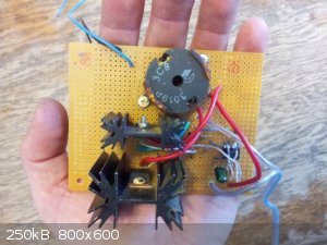
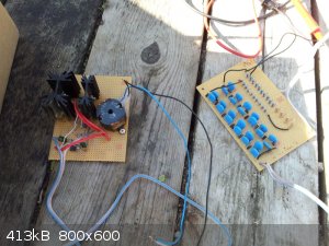
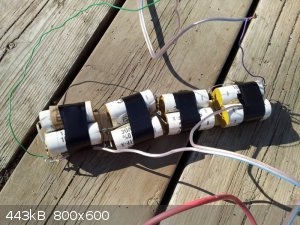
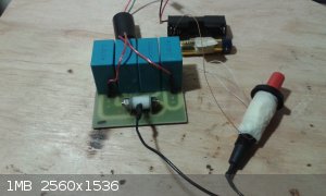
I'm getting the closer to being able to do some proper testing now ive got new capacitors, there Epcos 5uf 1300v radial metalized polypropylene film
with 0.006 ohm ESR I bought 4 so that gives me 5200v and 1.25 UF.
I had issues with mach3 on my cnc router that took time to work out so I just finished routing the board on the weekend but every thing seems to fit
on okay , I built the spark switch into the board to tidy things up a bit and keep it close to the capacitors.
I've taken a short video of the piezo fireing the spark switch but thats about it so far , cheers nuxy.
[Edited on 9-6-2015 by nux vomica]
|
|
|
nux vomica
Hazard to Others
Posts: 267
Registered: 18-7-2013
Member Is Offline
Mood: No Mood
|
|
Spark switch video
Attachment: 20150609_181820_001_001.3gp (9.3MB)
This file has been downloaded 831 times
|
|
|
Hennig Brand
International Hazard
Posts: 1284
Registered: 7-6-2009
Member Is Offline
Mood: No Mood
|
|
Looks very professional, well done. Those capacitors are far superior to what you had before for this purpose. You did a nice job of making a small
tidy spark gap switch. Your setup will be quite compact that is for sure, which is a good thing.
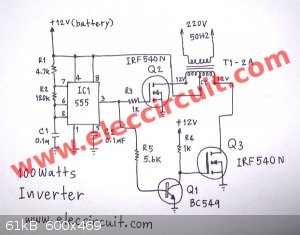
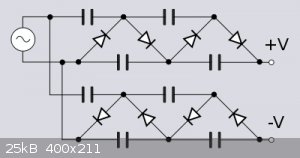
I have a bunch of 2153 chips now so I should probably make at least one inverter using one. The inverter based on the ubiquitous 555 is working well
enough for my purposes already though, at least in this application. The 2153 inverter circuit diagram below was taken from the following webpage:
http://danyk.cz/menic230_4_en.html
The 2153 datasheet has a graph allowing component choices to me made for a desired operating frequency.
Attachment: IR2153 Data Sheet.pdf (156kB)
This file has been downloaded 482 times
[Edited on 9-6-2015 by Hennig Brand]
"A risk-free world is a very dull world, one from which we are apt to learn little of consequence." -Geerat Vermeij
|
|
|
nux vomica
Hazard to Others
Posts: 267
Registered: 18-7-2013
Member Is Offline
Mood: No Mood
|
|
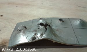
Just had a successful test used 0.030 mm dia x 1.6mm long copper bridgewire with .8 grm etn, dont know compression figures as in a rush but
compressed .7 then used .1 grm loose alloy tube 8mm id x20mm long at the end of 7 meters of rg6 coax and 200mm speaker twin core.
Charged capacitors for 11seconds volt measurement would be over 4500 volts didn't have gauge just used times tested in shed then hit piezo button nice
bang and a dent nearly through the 2mm s/s plate nice
[Edited on 10-6-2015 by nux vomica]
[Edited on 10-6-2015 by nux vomica]
[Edited on 10-6-2015 by nux vomica]
[Edited on 10-6-2015 by nux vomica]
|
|
|
Hennig Brand
International Hazard
Posts: 1284
Registered: 7-6-2009
Member Is Offline
Mood: No Mood
|
|
A positive result is nice. So the bridgewire was around 0.63 mils in diameter or 54 AWG right? Seems extremely thin, but if it works it works. Must be
very difficult not to break when handling. Was the bridgwire copper? It would have been nice to know more about the specifics of the test, such as
capacitor bank voltage prior to firing. Your assumption about the voltage could be right, but maybe not.
"A risk-free world is a very dull world, one from which we are apt to learn little of consequence." -Geerat Vermeij
|
|
|
nux vomica
Hazard to Others
Posts: 267
Registered: 18-7-2013
Member Is Offline
Mood: No Mood
|
|
I made a error on the wire dia have changed it in post to 0.030 mm or 1.225 mill (1 mill is 0.0245 mm so 0.030mm / 0.0245 equals 1.225 mill ) its
copper from flash transformer I cant measure voltage over 2800 volts at the moment as I am useing a 5 volt analog meter with 5 m ohm resistance and
power supply wont go over that level if connected, so I have run power for set times then touched wires on cap bank to measure the voltage.
Cheers nuxy.
[Edited on 11-6-2015 by nux vomica]
|
|
|
Hennig Brand
International Hazard
Posts: 1284
Registered: 7-6-2009
Member Is Offline
Mood: No Mood
|
|
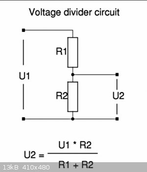
edit: Oh I see, the power supply is low current as suspected, which could also mean that it won't take too much abuse before it becomes damaged. Good
news it that it is fairly easy to build a decent power supply. It makes a nice little project in itself too.
Use a voltage divider which gives a lower proportional voltage for measuring. Even regular 1/4watt resistors can be used if enough of them are
connected in series. Often times they are only rated for a few hundred volts each IIRC, but if you add ten in series the series string can easily
handle a few thousand volts. High voltage resistors are also available, such as thick film resistors, if you want to go that route. I made a voltage
divider that has about 40Mohms resistance and my multimeter is attached to it at the appropriate place so that 4000V on the capacitor bank reads as
25V, but it could be any voltage you choose. The meter I am using is only rated for 1000V DC so there was no way I could use it to measure the 4000V
directly.
[Edited on 11-6-2015 by Hennig Brand]
"A risk-free world is a very dull world, one from which we are apt to learn little of consequence." -Geerat Vermeij
|
|
|
nux vomica
Hazard to Others
Posts: 267
Registered: 18-7-2013
Member Is Offline
Mood: No Mood
|
|
| Quote: Originally posted by Hennig Brand | | A positive result is nice. So the bridgewire was around 0.63 mils in diameter or 54 AWG right? Seems extremely thin, but if it works it works. Must be
very difficult not to break when handling. Was the bridgwire copper? It would have been nice to know more about the specifics of the test, such as
capacitor bank voltage prior to firing. Your assumption about the voltage could be right, but maybe not. |
I should listen to the quote about assumption being the mother of all fuxkups. 
|
|
|
Hennig Brand
International Hazard
Posts: 1284
Registered: 7-6-2009
Member Is Offline
Mood: No Mood
|
|
I have made a few assumptions in my time too and reaped the rewards.
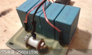
From the above picture it looks as though your power supply is being supplied by only two AA batteries. That in itself tells a lot about the limited
current supplying capability of the power supply. Power supplies have losses, usually quite significant especially with small power supplies, but lets
assume for a minute that yours has no losses (Power In = Power Out). Lets assume you can pull 1A from the two AA batteries at 3V. Using conservation
of energy, power in is 3V * 1A = 3W, so at 4500V the current drawn could be a maximum of 3W / 4500V = ca. 0.67mA. At 4500V the 5 Mohm Volt meter would
draw, 4500V / 5 000 000 ohm = 0.9mA (0.9mA > 0.67mA). I went through these same problems when I was using the bug zapper supplies.
"A risk-free world is a very dull world, one from which we are apt to learn little of consequence." -Geerat Vermeij
|
|
|
nux vomica
Hazard to Others
Posts: 267
Registered: 18-7-2013
Member Is Offline
Mood: No Mood
|
|
Had another test also successful l used same setup with copper bridgewire 0.030 x 1.6mm long .7 grams etn compressed to 1.49 grams cc and .1 gram
loose on top, 7 meters coax and 200mm twin speaker wire.
Haven't been able to get to electronic supply shop so don't have accurate voltage levels just charged for 11 seconds as before and pushed pezio button
detonation was instantaneous and plate was more damaged than last shot nuxy
[Edited on 11-6-2015 by nux vomica]
|
|
|
| Pages:
1
2
3
4
5
6
..
11 |


