| Pages:
1
..
6
7
8
9
10
11 |
retrofit
Harmless

Posts: 7
Registered: 12-7-2015
Member Is Offline
Mood: No Mood
|
|
| Quote: | | Retrofit, I used an MOT and full wave multiplier earlier in this thread and it works but is very inefficient and big and heavy. Also your capacitor
has an awful lot of capacitance. Is it actually a pulse rated cap with low ESR and low ESL? Even with relatively low circuit resistance and inductance
most of the charge on that capacitor will not be transferred before bridgewire burst. |
The capacitor C3 is actually a bank of metallized PE film capacitors sold as self-healing, low ESL/ESR/dissipation (cheap and ambiguous as to exact
specifications, "no inductance", etc.). I condensed all the capacitors to their calculated values (including C1 and C2) rather than draw the wiring of
each one. However, the LCR meter disagrees with the calculated values. I have 3 parallel strings of 2 capacitors each, all are 4.74uF. This should
give 7.11uF, but I measure 691.0nF across the bank. The ESR value measured floats all over (no idea why), ~1.4-2.3 ohms at 100 Hz, and 0.09 ohms at
100 kHz. Measured series inductance is 3.655 H at 100 Hz and 3.316 uH at 100 kHz (with fairly long connecting leads).
Edit: Well, I pulled a bonehead. They're 474nF caps, not 4.74uF caps. The numbers seem much more reasonable now. Calculated
capacitance is 711nF, actual is 691nF. Without the meter and your comment, I probably would have missed that. Thanks!
I edited my earlier post to make a note about incorrect values. (1/2) * (711nF) * (3850 volts)^2 = 5.3 joules. 5.3 joules over 10uS is 530kW. However,
I'm still worried about that ESR value. It seems awfully high.
[Edited on 22-7-2015 by retrofit]
|
|
|
Hennig Brand
International Hazard
Posts: 1284
Registered: 7-6-2009
Member Is Offline
Mood: No Mood
|
|
No problem, yeah, that makes more sense. Also I doubt the ESR is really that high and if it is there is likely a problem with one or more of the caps.
"A risk-free world is a very dull world, one from which we are apt to learn little of consequence." -Geerat Vermeij
|
|
|
retrofit
Harmless
Posts: 7
Registered: 12-7-2015
Member Is Offline
Mood: No Mood
|
|
Back to the drawing board for the trigatron. It wouldn't fire the gap with the capacitor bank in the circuit. I reversed the polarity, placing the
positive electrode in the center of the gap and the ground to the ground side of the capacitor bank. A quick search of the literature suggested that
trigatrons are sensitive to polarity. That yielded a small weak spark, so I closed up the gap to about 2mm, but it was no better (it appeared to fire
once, but was not repeatable). Touching the wires together to discharge the bank gave a noticeably more intense spark (heavy rubber gloves and proper
tongue angle required).
Nux vomica, how do you have your piezo igniter wired into your circuit?
Edit: Closing the gap to ~0.5mm and placing the positive electrode in the center and the ground on the negative side of the bank
caused the gap to break down reliably. Perhaps too reliably, because it would occasionally spark over by itself and conduct continuously. Opening it
back up to ~1.5mm worked for reliable breakdown, which coincides with the bank being charged to around 80% of theoretical breakdown voltage for the
gap.
[Edited on 22-7-2015 by retrofit]
|
|
|
markx
National Hazard
Posts: 645
Registered: 7-8-2003
Location: Northern kingdom
Member Is Offline
Mood: Very Jolly
|
|
Quote: Originally posted by Hennig Brand  |
No advantages? There are massive advantages going from 60Hz to 15kHz. Markx, check the Magnetics ferrite transformer design guide I posted here:
http://www.sciencemadness.org/talk/viewthread.php?tid=23466&...
With a 3019P pot core going from 20kHz to 50kHz increases the power handling capability from 48 Watts to 75 Watts. If the frequency is increased to
100kHz the power handling capability goes to 108W and at 250kHz, 210W. You are correct I could have used a higher frequency and reduced transformer
size and gained efficiency, but since I only need 5W or less and for only a very short duration how much practical difference does it make? Even going
with the relatively low frequency of 15kHz allows reasonably small capacitors to be used for the voltage multiplier and also reasonable efficiency at
the required current draw. I suppose battery life could be improved with higher frequency which is a consideration. If I was designing a 500W power
supply for continuous use I would be much more concerned with efficiency and keeping the component sizes as small as possible, but I am much less
concerned with a 5W power supply that is only run for 5-10 seconds every once in a while.
I am fairly new to inverter design and what I built is definitely not optimized, but it works and so far seems reliable.
[Edited on 22-7-2015 by Hennig Brand] |
I was a bit vague in my statement....pardon me. What I meant is that 15kHz design offers no advantages in hardware complication level compared to a
50kHz system. And of course a with a low power system one does not need to keep the efficacy sky high or the size as small as possible. Rather a
stable and reliable system is what we are after. I was just trying to offer some insight on generic principles that I have gathered from my own
experience 
Exact science is a figment of imagination.......
|
|
|
Hennig Brand
International Hazard
Posts: 1284
Registered: 7-6-2009
Member Is Offline
Mood: No Mood
|
|
I see what you mean, that I could have gone to 50kHz with little extra trouble and got some benefits for doing so. I didn't have enough experience
with it to know if going to 50kHz really wouldn't have caused extra complications, which was why I erred on the side of caution and kept the frequency
low at 15kHz.
"A risk-free world is a very dull world, one from which we are apt to learn little of consequence." -Geerat Vermeij
|
|
|
Hennig Brand
International Hazard
Posts: 1284
Registered: 7-6-2009
Member Is Offline
Mood: No Mood
|
|
I just received a couple of printed circuit boards and a couple of mini trigatrons from Nux Vomica, like the ones used for his EBW fireset. He does
very nice work. Since I have purchased some of the same capacitors a while back and inverters I could now easily assemble a fireset just like his. One
can never have too many EBW firesets. 
Thank you Mr. Vomica!
"A risk-free world is a very dull world, one from which we are apt to learn little of consequence." -Geerat Vermeij
|
|
|
nux vomica
Hazard to Others
Posts: 267
Registered: 18-7-2013
Member Is Offline
Mood: No Mood
|
|
| Quote: Originally posted by Hennig Brand | I just received a couple of printed circuit boards and a couple of mini trigatrons from Nux Vomica, like the ones used for his EBW fireset. He does
very nice work. Since I have purchased some of the same capacitors a while back and inverters I could now easily assemble a fireset just like his. One
can never have too many EBW firesets.
Thank you Mr. Vomica! |
No problems henning enjoy, you are spoiled for choice now  , i am intrested to see
what your thoughts are on the different setups. , i am intrested to see
what your thoughts are on the different setups.
If there is any interest I can post the sketchup file I used to rout my boards with, I'm also working on putting all the parts on one board which will
make things more compact . Cheers Nuxy.
[Edited on 25-7-2015 by nux vomica]
|
|
|
markx
National Hazard
Posts: 645
Registered: 7-8-2003
Location: Northern kingdom
Member Is Offline
Mood: Very Jolly
|
|
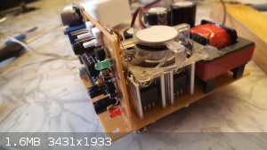
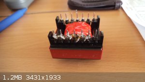
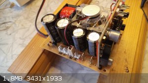
Was bored this saturday and decided to slap together a power converter based on the cheap chinese hf transformer from ebay. Turned out really well I
must say...about 300W of output power with adjustable output voltage from 12-500V dc. Can also be used as a powerful EBW charger if output is fed into
a voltage multiplier.
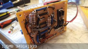
The switches are four irf3205 mosfets in a push-pull configuration. The "brain" is TL494 coupled with IR2110 to keep up with the relatively high gate
capacitance of the particular mosfets. The IC-s are powered by a separate SEPIC converter to keep the ic power voltage independent of battery voltage.
Output voltage is controlled by a non isoated feedback loop (through resistor bridge and smoothing capacitor) into error amp 1 of the TL494. There is
also the option to use error amp 2 as a current limiter to keep the circuit from overstressing itself in case of a shorted output. I did not implement
the current sense option yet, but it probably is a good idea now that I think about it 
Scope shot of voltage on mosfet drain (left) and on the gate (right) 33kHz:
There is basically no voltage overshoot on the drains....snubbers and fine tuned driving frequency do an excellent job
Going higher with the switching frequency did produce considerable distortion in the drain waveform and a loss of output power. I guess for 5$ the
transformers' core is not one of the brightest stars in the magnetic materials heaven
[Edited on 1-8-2015 by markx]
Exact science is a figment of imagination.......
|
|
|
Hennig Brand
International Hazard
Posts: 1284
Registered: 7-6-2009
Member Is Offline
Mood: No Mood
|
|
Well that is definitely a power supply and a fairly sophisticated one at that especially for an amateur, well done. Major overkill for an EBW fireset
power supply though I would judge, but to be honest I have never actually seen a power supply from one of the commercial models so I don't know for
sure.
"A risk-free world is a very dull world, one from which we are apt to learn little of consequence." -Geerat Vermeij
|
|
|
markx
National Hazard
Posts: 645
Registered: 7-8-2003
Location: Northern kingdom
Member Is Offline
Mood: Very Jolly
|
|
| Quote: Originally posted by Hennig Brand | | Well that is definitely a power supply and a fairly sophisticated one at that especially for an amateur, well done. Major overkill for an EBW fireset
power supply though I would judge, but to be honest I have never actually seen a power supply from one of the commercial models so I don't know for
sure. |
It is a step forward from the bug zappers for sure For a simple HV capacitance
charger it is perhaps overkill, but I don't mind the extra zap.
Exact science is a figment of imagination.......
|
|
|
Hennig Brand
International Hazard
Posts: 1284
Registered: 7-6-2009
Member Is Offline
Mood: No Mood
|
|
Poke fun at those bug zappers if you want to but they were merely stepping
stones and part of a learning process that ended with a fairly basic but reasonably good understanding of HV power supply design and of EBW technology
in general. You should set up a EBW system yourself. You already have a power supply and it really is a very reliable and safe way to go. It also
seems to appeal to technology nuts like us. The whole concept is very
interesting, or at least I find it so.
"A risk-free world is a very dull world, one from which we are apt to learn little of consequence." -Geerat Vermeij
|
|
|
TGT
Harmless
Posts: 46
Registered: 9-11-2014
Member Is Offline
Mood: No Mood
|
|
Is it possible to heat a small wire for electric ignition with just a car 12 volt battery? Sorry for the simple question. I have made one out of a
photo flash and it seems to work good, but wire distance is limited. May be more caps?
TGT
|
|
|
markx
National Hazard
Posts: 645
Registered: 7-8-2003
Location: Northern kingdom
Member Is Offline
Mood: Very Jolly
|
|
| Quote: Originally posted by Hennig Brand | | Poke fun at those bug zappers if you want to but they were merely stepping
stones and part of a learning process that ended with a fairly basic but reasonably good understanding of HV power supply design and of EBW technology
in general. You should set up a EBW system yourself. You already have a power supply and it really is a very reliable and safe way to go. It also
seems to appeal to technology nuts like us. The whole concept is very
interesting, or at least I find it so. |
Naaah...I'm actually thinking them electric tennis rackets were a pretty darn good idea. I mean "out of the box" solution for a fireset that only cost
pennies
Exact science is a figment of imagination.......
|
|
|
markx
National Hazard
Posts: 645
Registered: 7-8-2003
Location: Northern kingdom
Member Is Offline
Mood: Very Jolly
|
|
| Quote: Originally posted by TGT | Is it possible to heat a small wire for electric ignition with just a car 12 volt battery? Sorry for the simple question. I have made one out of a
photo flash and it seems to work good, but wire distance is limited. May be more caps?
TGT |
Of course it is possible...you just have to take into account the resistance of the cable itself and the voltage drop across it. At a certain length
the voltage drop on the cable itself will be big enough to prevent the ignition element from sufficiently heating up. At that point you have reached
the limit for that particular gauge/material cable. To increase the distance you have to use heavier cable or higher voltage. Adding parallel caps to
input will not help as it will neither up the voltage, nor affect the resistance of the circuit.
Exact science is a figment of imagination.......
|
|
|
Hennig Brand
International Hazard
Posts: 1284
Registered: 7-6-2009
Member Is Offline
Mood: No Mood
|
|
| Quote: Originally posted by markx |
Naaah...I'm actually thinking them electric tennis rackets were a pretty darn good idea. I mean "out of the box" solution for a fireset that only cost
pennies |
Thanks, you know it could have been made to work too if the current draw had been reduced by current limiting resistor(s) or inductor and loads such
as bleeder resistors and voltage divider were either taken out of circuit during charging or made much higher resistance. The truth is they were
awfully puny and there are better choices. Yeah, it seemed like a good idea at first.
They could be used for a disposable/consumable system with no blasting line, since the capacitor(s) required to fire the EBW detonator can be quite
small (lower voltage and capacitance) and long term power supply longevity is certainly not a factor since it will not survive the blast anyway.
"A risk-free world is a very dull world, one from which we are apt to learn little of consequence." -Geerat Vermeij
|
|
|
Gargamel
Hazard to Others
Posts: 166
Registered: 9-3-2013
Member Is Offline
Mood: No Mood
|
|
Capacitors in series - voltage distribution OK?
Have you guys ever measured the true voltage distribution over your caps?
The resistance of my measuring equipment (cheapo DMM 1MegOhm+ devider network, giving 10MegOhm) would be enough to severely affect balance, but if the
capacitance is large enough I could charge them without any bleeder and take the measurement quickly.
Capacitors in series suck. Only we have no (cheap) choice.
Besides, have you ever tried to match your capacitors, and if, how did you do it? My DMM has no capacitance function. I wonder if a cheapo capacitance
meter in the 15-20$ range is of any use.
|
|
|
Hennig Brand
International Hazard
Posts: 1284
Registered: 7-6-2009
Member Is Offline
Mood: No Mood
|
|
Nux and I have both been using series connected capacitors for a while now and it has been working quite well for both of us. Many Tesla coil
enthusiasts, likely thousands, have been using series connected capacitors as well. It may not be ideal, but it can work very well. Why don't you try
it? You may find that it works satisfactorily.
Good quality pulse caps, of the same type, are normally fairly well matched in terms of ESR, ESL and capacitance.
[Edited on 10-8-2015 by Hennig Brand]
"A risk-free world is a very dull world, one from which we are apt to learn little of consequence." -Geerat Vermeij
|
|
|
nux vomica
Hazard to Others
Posts: 267
Registered: 18-7-2013
Member Is Offline
Mood: No Mood
|
|
Gargamel these are the capacitors I use they aren't particularly expensive for four of them. http://m.ebay.com/itm/2-EPCOS-5uF-1300V-1kV-275V-250V-100V-radial-polypropylene-capacitors-/291095298708?nav=SEARCH
Cheers nuxy
[Edited on 10-8-2015 by nux vomica]
|
|
|
Gargamel
Hazard to Others
Posts: 166
Registered: 9-3-2013
Member Is Offline
Mood: No Mood
|
|
I got a large batch of 1,6KV/330nF rather cheap, but I like to see what's going on with them. If you they suffer from overvoltage, this might happen
slowly, loosing capacitance over time. I want something reliable.
Also my power source consisting basically of an enlarged bugzapper style blocking oscillator does not like all these loads, the voltage drops to much.
I need something stronger first.
I've got a CCFL inverter ready, if this thing does not work the way I want it, I'll get a TV transformer.
One question concerning your trigatrons:
Do your trigger circuits and main circuits share a common ground?
Your batteries too?
|
|
|
nux vomica
Hazard to Others
Posts: 267
Registered: 18-7-2013
Member Is Offline
Mood: No Mood
|
|
If you put three 330nf in series you only get 4800 volts 110nf you would have to parallel up a lot of caps to get to a decent uf figure.
[Edited on 10-8-2015 by nux vomica]
|
|
|
aldofad
Hazard to Self
Posts: 56
Registered: 30-6-2013
Member Is Offline
Mood: No Mood
|
|
This is an EBW I made time ago.
http://youtu.be/Ks6GFzZj8Vc
4500 V DC, rectified from a 10.000 V AC neon transformer. 1 micro F capacitor. PETN exploded correctly every time.
|
|
|
Gargamel
Hazard to Others
Posts: 166
Registered: 9-3-2013
Member Is Offline
Mood: No Mood
|
|
| Quote: |
4500 V DC, rectified from a 10.000 V AC neon transformer. 1 micro F capacitor. PETN exploded correctly every time. |
What kind of wire and capacitor did you use?
Don't worry Nux, I've got a box full of them.
How do you guys wire your trigger electrodes?
Right now I envision to put my main circuit and my trigger circuit on a common ground, so that there are only 3 electrodes. The spark would shoot from
a trigger electrode sitting very near to the positive main electrode to the common ground eletrode. That way it could ionize a large part of the gap.
The ground elektrode leads through the EBW to ground/capacitor -.
I could also use 4 electrodes and a completely separated circuit, shooting a spark across the main path.
My feeling is that the 3 electrode version would be more reliable.
|
|
|
aldofad
Hazard to Self
Posts: 56
Registered: 30-6-2013
Member Is Offline
Mood: No Mood
|
|
3 capacitor of type Type 940C, Polypropylene Capacitors
Regarding the wire, I simply used a microfilament taken from inside a common pin cable, that's just because I'm plenty of those.
|
|
|
Grantr
Hazard to Self
Posts: 57
Registered: 19-9-2015
Member Is Offline
Mood: No Mood
|
|
I have read this thread a few times and have somewhat of an idea of how to make a unit. Attached is a schematic of how I think it goes together.
For the HV power source I plan to use
this:http://www.ebay.com/itm/Applied-DC-3-6V-6V-400KV-Boost-Step-up-Power-Module-High-voltage-Generator-1pc-/221786184145?hash=item33a37c99d1
For the caps 4 of these:http://www.ebay.com/itm/2-EPCOS-5uF-1300V-1kV-275V-250V-100V-radial-polypropylene-capacitors-/291095298708?hash=item43c6a1c294
I know the caps have to all be tied in series to handle 4kv so I will have 5200v at 1.25UF. To keep it safe, I plan to charge to 4500v.
For the bleeder resistors would I use one 1Mohm resistor across each pair of caps? What voltage rating would the resistors need to be?
What size resistors form the HV source?
Attachment: bridge wire circuit.pdf (85kB)
This file has been downloaded 470 times
|
|
|
Aurium
Harmless
Posts: 46
Registered: 4-10-2015
Member Is Offline
Mood: Energetic
|
|
Grant,
You wont really need a bleeder resistor for an EBW setup. Just make sure you discharge the capacitors before you touch them.
There isn't a need for resistors from the HV module to the caps.
Now, from the circuit schematic you provided, I can't help but notice that you'r knowledge of electronics is, at best, basic.
At the same time you'r dealing with very high voltages, a potentially deadly combination.
If you want my advice, get an electronics kit from ebay and start playing around with the basics, using low voltage. Once you feel confident enough
them go ahead and experiment with HV, carefully.
Thrust me. A couple of months of experimenting with low voltages is enough to give you allot of crucial knowledge.
|
|
|
| Pages:
1
..
6
7
8
9
10
11 |


/Pololu-3-Conductor-JST-to-Male-Pin-Cable-30cm-(White%252BBlack%252BRed)-600x600.jpg&imgrefurl=https://www.bananarobotics.com/shop/Pololu-3-Conductor-JST-to-Male-Pin-Cable-30cm-(White-Black-Red)&h=600&w=600&tbnid=lT39ByVohNDIgM:&docid=rKm4M2a6EIdjpM&ei=jN3JVfzICMf-UJaWl7gL&tbm=isch&ved=0CCAQMygAMABqFQoTCPy-rsb3oMcCFUc_FAodFssFtw)