| Pages:
1
..
4
5
6
7
8
..
11 |
nux vomica
Hazard to Others

Posts: 267
Registered: 18-7-2013
Member Is Offline
Mood: No Mood
|
|
Old marvin is a classic i remember watching him on a black and white tv as a kid 
[Edited on 24-6-2015 by nux vomica]
|
|
|
Hennig Brand
International Hazard
Posts: 1284
Registered: 7-6-2009
Member Is Offline
Mood: No Mood
|
|
Giving away your age I see.  I am not one of the old and wise here, but I am not
one of the kids either, I am about half way in between at this point I guess. I am not one of the old and wise here, but I am not
one of the kids either, I am about half way in between at this point I guess.
You mentioned using Delrin on the last page, it is excellent material for making bobbins for high voltage transformers, IIRC. Instead of layer winding
(one on top of the other), like how I wound the 500V transformer for my power supply, a bobbin can be made on a lathe from Delrin round stock by
cutting sections out along its length for the windings and leaving insulating dividers. After winding it is vacuum potted in epoxy resin or some other
suitable insulator that can be applied as a liquid, will cure and hold up well. Here is a picture of the type of bobbin I am talking about. The
picture is of a HV (ca. 50kV) output transformer for a stungun.
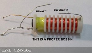
edit: I just remembered that it was glass filled Delrin that was suggested to me by an electronics designer for making high voltage transformer
bobbins. I can't remember any more specifics.
[Edited on 27-6-2015 by Hennig Brand]
"A risk-free world is a very dull world, one from which we are apt to learn little of consequence." -Geerat Vermeij
|
|
|
nux vomica
Hazard to Others
Posts: 267
Registered: 18-7-2013
Member Is Offline
Mood: No Mood
|
|
Quote: Originally posted by Hennig Brand  | Giving away your age I see. I am not one of the old and wise here, but I am not
one of the kids either, I am about half way in between at this point I guess.
You mentioned using Delrin on the last page, it is excellent material for making bobbins for high voltage transformers, IIRC. Instead of layer winding
(one on top of the other), like how I wound the 500V transformer for my power supply, a bobbin can be made on a lathe from Delrin round stock by
cutting sections out along its length for the windings and leaving insulating dividers. After winding it is vacuum potted in epoxy resin or some other
suitable insulator that can be applied as a liquid, will cure and hold up well. Here is a picture of the type of bobbin I am talking about. The
picture is of a HV (ca. 50kV) output transformer for a stungun.
edit: I just remembered that it was glass filled Delrin that was suggested to me by an electronics designer for making high voltage transformer
bobbins. I can't remember any more specifics.
[Edited on 27-6-2015 by Hennig Brand] |
Hey dinosaurs ruled the earth once 
Ive seen round ferrite cores before on transformers but why split the secondary up , phasing , winding density . nuxy
[Edited on 27-6-2015 by nux vomica]
|
|
|
Hennig Brand
International Hazard
Posts: 1284
Registered: 7-6-2009
Member Is Offline
Mood: No Mood
|
|
This would only be if you were going to omit the voltage multiplier and make a 5 or 6 thousand volt transformer. Yeah, the core in that picture is a
ferrite rod and the transformer is meant to act in flyback mode I believe. A different core could be used, such as an E-Core. The special bobbin,
winding style and vacuum potting in epoxy allows much better separation and insulation between windings which is designed to prevent arcing between
windings, especially between the primary and secondary. I am not a transformer expert and have done most of my learning online.
I meant no disrespect with the comments about your age. We are all getting older, I feel like I blinked twice and I went from being a teenager to
closer to 40. How the hell did that happen? If I could go back knowing what I know now I would, but to go back and be as ignorant as I was then, no
thank you. "Youth is wasted on the young." - George Bernard Shaw
[Edited on 27-6-2015 by Hennig Brand]
"A risk-free world is a very dull world, one from which we are apt to learn little of consequence." -Geerat Vermeij
|
|
|
nux vomica
Hazard to Others
Posts: 267
Registered: 18-7-2013
Member Is Offline
Mood: No Mood
|
|
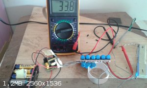
I just got a result with my inverter voltage multiplier I was stuck on 2000v reading when I remembered about using larger capacitor values for slower
frequency's so I joined 3 more rows underneath and if I take out the voltage from the end of the fourth row I get 5438v .
I am lazy these days and bought the inverter on fleabay http://www.ebay.com.au/itm/221596931989?_trksid=p2060353.m1438.l2649&ssPageName=STRK%3AMEBIDX%3AIT and I run it on 12v
The voltage divider is r1 40,000,000 ohms, r2 250,000 0hms to give you 31.056v at the measureing point ,the voltage calculation is 5000v divided by
31.056v to gives you 160.9 volts so 33.8 x 160.9 =5438 volts.
Now to try it out 
Cheers nuxy.
[Edited on 27-6-2015 by nux vomica]
|
|
|
Hennig Brand
International Hazard
Posts: 1284
Registered: 7-6-2009
Member Is Offline
Mood: No Mood
|
|
Well that certainly is a cost and labor effective way to go. I am tempted to order one of those myself. I wonder what the operating frequency is for
your inverter. If the frequency and capacitor values are too low the output voltage will drop out when even a small load is applied.
"A risk-free world is a very dull world, one from which we are apt to learn little of consequence." -Geerat Vermeij
|
|
|
nux vomica
Hazard to Others
Posts: 267
Registered: 18-7-2013
Member Is Offline
Mood: No Mood
|
|
| Quote: Originally posted by Hennig Brand |
I meant no disrespect with the comments about your age. We are all getting older, I feel like I blinked twice and I went from being a teenager to
closer to 40. How the hell did that happen? If I could go back knowing what I know now I would, but to go back and be as ignorant as I was then, no
thank you. "Youth is wasted on the young." - George Bernard Shaw
[Edited on 27-6-2015 by Hennig Brand] |
Don't give it a second thought I don't mind a bit of shit stirring the politicaley correct thought police are wasting there time on me.
yeh to know what I know now and go back, id probably go back slap myself around and then tell myself to pull my socks up and try harder at school you
dum shit.
|
|
|
nux vomica
Hazard to Others
Posts: 267
Registered: 18-7-2013
Member Is Offline
Mood: No Mood
|
|
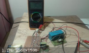
Whent and connected the epicos capacitor bank to the inverter setup was getting 37v could only get to 30v for picture ? so it work's but I think I
shorted something out cos got a loud bang thst scared the crap out of me  bugger
wil check it out tomorrow . bugger
wil check it out tomorrow .
[Edited on 28-6-2015 by nux vomica]
|
|
|
Hennig Brand
International Hazard
Posts: 1284
Registered: 7-6-2009
Member Is Offline
Mood: No Mood
|
|
Seems like you might be overcharging, 37V across R2 would be close to 6000V on the capacitor bank. The other thing to keep in mind is that series
connected capacitors even of the same type are not perfectly identical and will not share the charge/voltage equally. One of the functions of bleeder
resistors on the capacitors is to function as bypass resistors which act to even out the charge/voltage and help keep a balance. If you capacitor bank
is rated for 5200V, then only going to 80% of that or maybe even less especially when connected in series would probably be wise. Regarding the loud
bang it could have been on the board somewhere with the voltage multiplier. I ground the copper traces off of my board between the two voltage
multipliers, etc, because I was getting arc over at high voltages.
"A risk-free world is a very dull world, one from which we are apt to learn little of consequence." -Geerat Vermeij
|
|
|
nux vomica
Hazard to Others
Posts: 267
Registered: 18-7-2013
Member Is Offline
Mood: No Mood
|
|
| Quote: Originally posted by Hennig Brand | | Seems like you might be overcharging, 37V across R2 would be close to 6000V on the capacitor bank. The other thing to keep in mind is that series
connected capacitors even of the same type are not perfectly identical and will not share the charge/voltage equally. One of the functions of bleeder
resistors on the capacitors is to function as bypass resistors which act to even out the charge/voltage and help keep a balance. If you capacitor bank
is rated for 5200V, then only going to 80% of that or maybe even less especially when connected in series would probably be wise. Regarding the loud
bang it could have been on the board somewhere with the voltage multiplier. I ground the copper traces off of my board between the two voltage
multipliers, etc, because I was getting arc over at high voltages. |
Yes letting it get to 37v was probably pushing it, the multiplier network was where I suspected the bang came from as well ,when you play with
electricity you will always get the magic smoke sometime
What value are your bleeder resistors hennig?.
cheers nuxy.
[Edited on 28-6-2015 by nux vomica]
|
|
|
Hennig Brand
International Hazard
Posts: 1284
Registered: 7-6-2009
Member Is Offline
Mood: No Mood
|
|
I have four pairs of capacitors in a series string with a half Watt, 10Mohm, HV resistor across each capacitor pair for a total of 40Mohms. There are
formulas and rules of thumb for selecting bypass resistors. If the resistance is too high is doesn't even out the voltage/charge as well and if too
low it puts a large load on the power supply, drains the capacitors very quickly and wastes precious battery power. It isn't really that critical as
long as a reasonable value is chosen though. The 10Mohm resistors I am using are a fairly standard value used by the Tesla coil people for this same
purpose on their capacitor banks. Since the charging rate is fairly slow even higher value resistors could easily be used though. The other benefit is
that the bypass resistors act as bleeder resistors and drain the capacitors completely within a reasonably short time after charging is stopped.
[Edited on 28-6-2015 by Hennig Brand]
"A risk-free world is a very dull world, one from which we are apt to learn little of consequence." -Geerat Vermeij
|
|
|
nux vomica
Hazard to Others
Posts: 267
Registered: 18-7-2013
Member Is Offline
Mood: No Mood
|
|
Hennig am I right in saying your bleeder resistors only go between each pair of capacitors so if I only have 4 in series do you need a resistor in
series with the capacitor series?
Woh thats a tounge twister .
[Edited on 29-6-2015 by nux vomica]
|
|
|
Hennig Brand
International Hazard
Posts: 1284
Registered: 7-6-2009
Member Is Offline
Mood: No Mood
|
|
One across each pair in the series string, in parallel with each pair. You would have one in parallel with each capacitor. I also have 10X100kohm
resistors in series (1Mohm total) between the power supply and the capacitor bank to limit charging current and to provide isolation between the power
supply and capacitor bank at discharge. I also have the voltage divider of course for voltage monitoring, which I believe is about 40Mohm as well. The
resistance values I have chosen are likely not ideal, but it should give you an idea. Higher resistance values would put less load on the power supply
and depending on how much higher might work nearly as well.
"A risk-free world is a very dull world, one from which we are apt to learn little of consequence." -Geerat Vermeij
|
|
|
nux vomica
Hazard to Others
Posts: 267
Registered: 18-7-2013
Member Is Offline
Mood: No Mood
|
|
| Quote: Originally posted by Hennig Brand | | One across each pair in the series string, in parallel with each pair. You would have one in parallel with each capacitor. I also have 10X100kohm
resistors in series (1Mohm total) between the power supply and the capacitor bank to limit charging current and to provide isolation between the power
supply and capacitor bank at discharge. I also have the voltage divider of course for voltage monitoring, which I believe is about 40Mohm as well. The
resistance values I have chosen are likely not ideal, but it should give you an idea. Higher resistance values would put less load on the power supply
and depending on how much higher might work nearly as well. |
Thanks hennig for the info cheers nuxy.
|
|
|
nux vomica
Hazard to Others
Posts: 267
Registered: 18-7-2013
Member Is Offline
Mood: No Mood
|
|
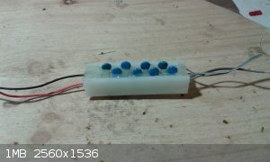
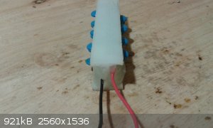
Decided to rebuild and permanently pot the voltage doubler as I blew a diode when I had the bang earlier ,I only need 4 stages and don't need the
extra caps as I thought before so I machined a piece of delrin at work on the milling m/c then hot glued the assembly in the H section to insulate it
from further mishaps ,I also need to put in the 1meg resistor as the epicos caps charge in 3 to 4 seconds, I would like to slow things down so its a
bit easier to just go over what voltage you want then let the bleeders drop the voltage to what you want.
cheers nuxy
[Edited on 30-6-2015 by nux vomica]
|
|
|
PHILOU Zrealone
International Hazard
Posts: 2893
Registered: 20-5-2002
Location: Brussel
Member Is Offline
Mood: Bis-diazo-dinitro-hydroquinonic
|
|
I'm sure sortly you will come to those
500 kV switch
I know that video for decades now, but it is still fascinating to me how the electricity flows not by the shortest way...if follows the ionisation
channel of arc warmed air...reason why it lifts up and elongates before shutting down.
PH Z (PHILOU Zrealone)
"Physic is all what never works; Chemistry is all what stinks and explodes!"-"Life that deadly disease, sexually transmitted."(W.Allen)
|
|
|
Hennig Brand
International Hazard
Posts: 1284
Registered: 7-6-2009
Member Is Offline
Mood: No Mood
|
|
Very interesting video, good demonstration, thanks for sharing.
"A risk-free world is a very dull world, one from which we are apt to learn little of consequence." -Geerat Vermeij
|
|
|
Gargamel
Hazard to Others
Posts: 166
Registered: 9-3-2013
Member Is Offline
Mood: No Mood
|
|
Concerning your capacitor banks:
Do you think it's OK to put them in series and charge them to almost their tested voltage?
I mean, you never know if the voltage is distributed evenly. Maybe some have a greater leak current then others.
Or one of them fails, in this case it will ruin the others too.
Concerning the bugzappers:
| Quote: |
After about three successful tests I noticed that the bug zapper supplies were charging the capacitor bank up to lower and lower voltages until they
wouldn't even charge the bank up to 2000V anymore |
Any idea why they loose power that way? Normally I would assume a sudden death if semiconductors die, not a slow decrease of power.
If it's capacitors or resistors, those could be replaced by stronger/better quality types.
OT:
| Quote: |
Weak bug zappers are outlawed when I come from from an animal welfare point of view. Only bug zappers of a minimum 1/2CV^2 are allowed on sale. The
cheap one leave the bug riding the lightning too long before death and are very cruel! |
IMHO there's only one kind of insect I like to kill with these, and that's culex mosquitos in the home or workplace. For these you don't need much
power. Just so much that they stick to the racket. Dump em in the sink/toilet - goodbye. To much power and you'll burn them in a way that their
residues spoil the racket over time.
|
|
|
Hennig Brand
International Hazard
Posts: 1284
Registered: 7-6-2009
Member Is Offline
Mood: No Mood
|
|
| Quote: Originally posted by Gargamel | Concerning your capacitor banks:
Do you think it's OK to put them in series and charge them to almost their tested voltage?
I mean, you never know if the voltage is distributed evenly. Maybe some have a greater leak current then others.
Or one of them fails, in this case it will ruin the others too.
|
Putting the capacitors in series is not ideal, but with reasonably well matched capacitors, suitable bypass resistors and by not overcharging it works
quite well. It is common practice by many of the Tesla coil enthusiasts to put these kinds of capacitors in series strings much longer than we have
done. The big thing to prevent capacitor damage is to not overcharge the capacitor bank. Discharging the capacitor bank into very low inductance, low
resistance, loads can put a lot of strain on the capacitors too and will cause accelerated degradation (very short blasting line or blade of
screwdriver, etc). I have been probably pushing the limits a bit by charging my 4000V bank to 3800V, but these types of capacitors can normally handle
considerably more than their rated voltage. It would probably be best to charge to a somewhat lower voltage however.
Regarding the bug zapper supplies, they were not able to supply a suitably high current and I also believe they were fighting against each other
(outputs out of phase) to some extent when hooked up together in series. I imagine the tiny windings in the tiny transformers were becoming damaged
when they eventually started to fail, but I didn't put much energy into investigation. They really weren't very suitable for the application, too
puny.
[Edited on 8-7-2015 by Hennig Brand]
"A risk-free world is a very dull world, one from which we are apt to learn little of consequence." -Geerat Vermeij
|
|
|
Gargamel
Hazard to Others
Posts: 166
Registered: 9-3-2013
Member Is Offline
Mood: No Mood
|
|
| Quote: |
Regarding the bug zapper supplies, they were not able to supply a suitably high current |
And if you increase your bleeders? And my add another multiplier stage?
This will take very long to charge though...
I'm just lazy that's all. I know there are better solutions, but I'd like to have something small, portable.
Kemo M062 with additional multiplier would be another idea.
I just searched the hell about suitable capacitors, this really expensive.
The combination nux vomica has choosen - 4x Epcos 5uF 1300V is really the cheapest I could find, ~13€. Every other combination is much more
expensive.
If that is not enough, one could put another 4 in parallel.
Thank you for posting all this appetizers. You just made me hungry
edit:
Hennig, do you have an ESR value for your 1µ/1000V caps?
[Edited on 8-7-2015 by Gargamel]
|
|
|
nux vomica
Hazard to Others
Posts: 267
Registered: 18-7-2013
Member Is Offline
Mood: No Mood
|
|
| Quote: Originally posted by Gargamel | | Quote: |
Regarding the bug zapper supplies, they were not able to supply a suitably high current |
And if you increase your bleeders? And my add another multiplier stage?
This will take very long to charge though...
I'm just lazy that's all. I know there are better solutions, but I'd like to have something small, portable.
Kemo M062 with additional multiplier would be another idea.
I just searched the hell about suitable capacitors, this really expensive.
The combination nux vomica has choosen - 4x Epcos 5uF 1300V is really the cheapest I could find, ~13€. Every other combination is much more
expensive.
If that is not enough, one could put another 4 in parallel.
Thank you for posting all this appetizers. You just made me hungry
edit:
Hennig, do you have an ESR value for your 1µ/1000V caps?
[Edited on 8-7-2015 by Gargamel] |
You can use these http://www.ebay.com/itm/DC-3V-to-7kV-Boost-High-voltage-Generator-Booster-Ignition-Coil-Power- to get your high voltage.
4 of the epicos caps are enough you don't really need over 1 uf.
This is a link for further back in the thread http://www.sciencemadness.org/talk/files.php?pid=404525&... about the esr of hennigs capacitors.
cheers nuxy
|
|
|
Hennig Brand
International Hazard
Posts: 1284
Registered: 7-6-2009
Member Is Offline
Mood: No Mood
|
|
Using a lot of capacitance is pointless. The energy that is delivered to the bridgewire has to be delivered in well under a microsecond normally. It
is power (energy delivered / time) that is important not a huge amount of stored joules/energy. If you look at the ESR of the capacitor bank and add
it to the resistance of the switch, the cables, connections and bridgewire (all circuit resistance) and know that the time constant for capacitor
discharge is the product of the capacitance in Farads and resistance in Ohms (tau = RC) or the time in seconds it takes to discharge to 37% of full
charge it becomes clear. Charge on the capacitor bank is equal to the product of the capacitance in Farads and the charge voltage (Q = CV). Of course
it is more complicated than this because there is not only resistance to consider but also circuit inductance and capacitance (impedance), but even
just looking at the RC time constant, and charge equation, shows that what is needed is high voltage and low ESR, not huge amounts of capacitance. I
am only using a 0.5uF capacitor bank and most of the commercial models use 1uF and those commercial models are designed to be able to fire multiple
caps simultaneously in series/parallel configurations. Not only are these types of capacitors expensive, but storing large amounts of joules in high
voltage capacitors can be just plain dangerous too, never mind the fact that it is pointless from a performance perspective. There has to be a certain
amount of capacitance, but the point of diminishing return is reached very quickly much more quickly than most people imagine.
I actually haven't used the capacitors that I bought yet, I am still using the snubber capacitors that I salvaged from old variable frequency drive
(VFD) motor controllers found at a scrap yard. They likely have very similar specs to the ones in the data sheet though, since they are of the same
general type.
[Edited on 9-7-2015 by Hennig Brand]
"A risk-free world is a very dull world, one from which we are apt to learn little of consequence." -Geerat Vermeij
|
|
|
Gargamel
Hazard to Others
Posts: 166
Registered: 9-3-2013
Member Is Offline
Mood: No Mood
|
|
I'm aware of that.
The idea behind putting another string parallel is to halve ESR and ESL.
| Quote: |
If you look at the ESR of the capacitor bank and add it to the resistance of the switch, the cables, connections and bridgewire (all circuit
resistance) |
Have you ever calculated if the ESR of the capacitors itself is so critical?
I mean, if the rest is of rather high resistance, what's the point...?
Where's the most serious bottleneck for the sharpest possible rise?
|
|
|
Hennig Brand
International Hazard
Posts: 1284
Registered: 7-6-2009
Member Is Offline
Mood: No Mood
|
|
The most important resistance variable other than the capacitor(s) in a reasonably well designed system is the transmission line and unless a very
poor choice is made when selecting a cable its resistance is so low, and more difficult to change, as to not be nearly as much of a factor as that of
the capacitor(s). The switch and connections, etc, can also be significant, especially if designed poorly. Choosing the right type of capacitor is by
far one of the most, if not the most, important variable. Of course if so determined, or as the result of a serious lack of understanding, high
resistance and high inductance could be added to a system which would prevent the system from functioning properly even with a capacitor bank with the
lowest ESR and ESL possible. It is of course a system with all components contributing, but capacitor selection is an area where by far some of the
biggest overall effects on the system can be made.
Inductance is normally the biggest limiting factor to current rate of rise in actual systems, from what I have seen.
Have a look at this, from earlier in this very thread:
http://www.sciencemadness.org/talk/viewthread.php?tid=23466&...
edit:
Yeah, once you are into pulse rated type capacitors the difference from one type to another may not be that great overall. Going from an electrolytic
with 5 ohms of ESR to a pulse cap (e.g. metal film or foil) with 5 milliohms of ESR makes a huge difference, but going from a pulse cap with 10
milliohms to one with 5 milliohms when the blasting line has 0.5 ohms of resistance is not nearly as significant. Low ESR is important for capacitor
longevity as well though, not just speed, since the current and current rate of rise involved is massive. Low ESR capacitors dissipate less
heat/energy and will not get destroyed nearly as easily or quickly in pulsed power applications as capacitors with significantly higher ESR. Even
relatively small amounts of resistance in a capacitor can cause great mechanical stresses and damage with large currents and fast current rise.
Low ESL is also very important for fast current rate of rise.
[Edited on 9-7-2015 by Hennig Brand]
"A risk-free world is a very dull world, one from which we are apt to learn little of consequence." -Geerat Vermeij
|
|
|
Hennig Brand
International Hazard
Posts: 1284
Registered: 7-6-2009
Member Is Offline
Mood: No Mood
|
|
Blasting Line / Transmission Line / Firing Line
Even regular lamp cord and speaker wire seem to have reasonably suitable specifications, especially since both are so common. The following was taken
from Wikipedia:
"Ordinary lamp cord has an inductance of 0.1–0.2 μH/foot, likewise for shielded cord,[6] so a run of up to about 5 feet (10 total feet of
conductor) will have less than 1% inductive loss in the audible range. Some premium speaker cables have lower inductance at the cost of higher
capacitance; 0.02-0.05μH/foot is typical, in which case a run of up to about 25 feet (50 feet of conductor) will have less than 1% inductive loss."
I collected a few datasheets on some common coaxial cables a while back, but never bothered to post them. It is good information to have when one is
trying to make system comparisons. I see that I have saved the Wiki article on speaker wire as well as a pdf, hopefully as long as I give credit it is
ok to post it.
There are better cables as well, not listed here, that the commercial people sometimes use.
Attachment: RG-6U Data Sheet.pdf (99kB)
This file has been downloaded 413 times
Attachment: RG-8U Data Sheet.pdf (95kB)
This file has been downloaded 349 times
Attachment: RG-8X Data Sheet.pdf (95kB)
This file has been downloaded 379 times
Attachment: RG-11U Data Sheet.pdf (96kB)
This file has been downloaded 337 times
Attachment: RG-58U Data Sheet.pdf (92kB)
This file has been downloaded 363 times
Attachment: RG-59U Data Sheet.pdf (93kB)
This file has been downloaded 343 times
Attachment: RG-213U Data Sheet.pdf (94kB)
This file has been downloaded 343 times
Attachment: Speaker wire - Wikipedia, the free encyclopedia.pdf (424kB)
This file has been downloaded 498 times
[Edited on 9-7-2015 by Hennig Brand]
"A risk-free world is a very dull world, one from which we are apt to learn little of consequence." -Geerat Vermeij
|
|
|
| Pages:
1
..
4
5
6
7
8
..
11 |


