| Pages:
1
..
40
41
42
43
44
..
47 |
testimento
Hazard to Others
  
Posts: 351
Registered: 10-6-2013
Member Is Offline
Mood: No Mood
|
|
Does anyone have knowledge or experience on lead acetate electroplating PbO2 on graphite?
|
|
|
UncleJoe1985
Hazard to Self
 
Posts: 88
Registered: 30-9-2008
Location: Sunnyvale, CA
Member Is Offline
Mood: No Mood
|
|
use tin as a substrate?
| Quote: | | Does anyone have knowledge or experience on lead acetate electroplating PbO2 on graphite? |
I've made 2 attempts using the easier to obtain acetate.
The results are extremely crude due to not controlling the parameters to be within spec.
1st attempt (simple proof of concept):
coating was extremely flaky and crystal like, with minimal adhesion (could easily wipe it off)
Not surprising since I used no agitation to remove bubbles, room temperature, current density was too high (15mA/cm2), used too much
CuSO4 that it seemed to displace the lead from solution, cathode current density too low (why does it recommend it to be 2x the anode
current density - to prevent lead from plating out?)
2nd attempt - this time I used a heat gun to heat the solution and provide slight agitation
Result:
No longer flaky and better adhesion after drying, but very spongy instead of solid. I measured the resistance between 2 points 1cm apart and it was
~200 ohms. The graphite rod I used was 10cm x 1cm.
Next: use lower current density, do better job of removing bubbles, use less CuSO4
|
|
|
UncleJoe1985
Hazard to Self
 
Posts: 88
Registered: 30-9-2008
Location: Sunnyvale, CA
Member Is Offline
Mood: No Mood
|
|
OMG, I'm an idiot for using CuSO4 
That would ruin the plating solution by precipitating the lead out as sulfate! And I used so much CuSO4.
I was wondering what all that white crud at the bottom was. Guess I'll try again with copper acetate.
I think I intuitively understand why copper plates out before lead at the cathode. To explain it in simple physics principles, copper is less reactive
than lead, meaning it's harder to ionize. That would mean the Cu ions have a higher electrostatic potential energy. Since the lowest potential energy
state is favored, the electrons go to Cu2+.
But what about at the anode? Does oxidation of copper to copper oxides compete with Pb2+ + 2 H2O -> PbO2 + 4
H+ + 4e- (correct me if I'm wrong)
Can anyone point me to the relevant electrode potentials involved?
[Edited on 10-5-2015 by UncleJoe1985]
|
|
|
Jstuyfzand
Hazard to Others
  
Posts: 166
Registered: 16-1-2016
Location: Netherlands
Member Is Offline
Mood: Learning, Sorta.
|
|
What do you all think of this video? Seems pretty good!
https://www.youtube.com/watch?v=bZMWEYiTtso
|
|
|
Laboratory of Liptakov
International Hazard
    
Posts: 1334
Registered: 2-9-2014
Location: Technion Haifa
Member Is Offline
Mood: cool.gif
|
|
Is possible pure PbO2 pressed ? Pressure 12 000 Kg on cm2. And making 10 cm long rod from pure PbO2 ? Diameter 15 mm. How is electric conduction -
resistance for PbO2 ? And If is impossible pressed pure PbO2, is possible adding some material for increase solid ? For example, 7% nitrocellulose is
confirmed as very good solid - agent. For any fine-powder materials. What using 5% epoxide ? Or some different additivum for increase solidity? Anode
will be for prepare NaClO4, of course. Will be nitrocellulose do it problems ? Thanks, ...LL...
|
|
|
PHILOU Zrealone
International Hazard
    
Posts: 2893
Registered: 20-5-2002
Location: Brussel
Member Is Offline
Mood: Bis-diazo-dinitro-hydroquinonic
|
|
Quote: Originally posted by Laboratory of Liptakov  | Is possible pure PbO2 pressed ? Pressure 12 000 Kg on cm2. And making 10 cm long rod from pure PbO2 ? Diameter 15 mm. How is electric conduction -
resistance for PbO2 ? And If is impossible pressed pure PbO2, is possible adding some material for increase solid ? For example, 7% nitrocellulose is
confirmed as very good solid - agent. For any fine-powder materials. What using 5% epoxide ? Or some different additivum for increase solidity? Anode
will be for prepare NaClO4, of course. Will be nitrocellulose do it problems ? Thanks, ...LL... |
I don't know for the pressed PbO2 stick/rod and properties...
What I know:
Nitrocellulose will be unstable cement because in basic media (what the cell will increase (bleach is already stongly basic for stability and to avoid
toxic Cl2, Cl2O, ClO2 gas generation)) it will be hydrolysed into cellulose...thus setting NO3(-) free (good or bad?)...
Now, I don't know how cellulose behaves into a bleach-chlorate-perchlorate cell...but that's easy to find out (by experiment))...will it remain
integer or will it be chewed/schreded into pieces?
The following document:
Cellulose solvents and dissolution medias seems to mention that NaOH (7-10%) is able to dissolve cellulose...
You can also make Sweitzers type of solvent or Cellulose xanthan and the precipitate the cellulose into the PbO2 rod...maybe you could work with
cellophane another form of polymerized cellulose.
Epoxyde should remain stable into basic media...only into strongly acidic media it would be hydrolysed (but acidic is uncompatible with bleach...so
should be OK).
PH Z (PHILOU Zrealone)
"Physic is all what never works; Chemistry is all what stinks and explodes!"-"Life that deadly disease, sexually transmitted."(W.Allen)
|
|
|
Laboratory of Liptakov
International Hazard
    
Posts: 1334
Registered: 2-9-2014
Location: Technion Haifa
Member Is Offline
Mood: cool.gif
|
|
PbO2 anode
Thanks, epoxide as binder can be maybe a good material. During next study is clearly , that surface must be perfectly, without micro holes in the
surface. Thus, electro deposition on some substrate is necessary process. Unfortunately. Still more thanks, I making it on this. ..LL...
|
|
|
yobbo II
National Hazard
   
Posts: 709
Registered: 28-3-2016
Member Is Offline
Mood: No Mood
|
|
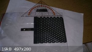
Lead dioxide anode for sale 30 dollars + shipping
read all about it here
http://www.amateurpyro.com/forums/topic/1629-making-potassiu...
|
|
|
ecos
Hazard to Others
  
Posts: 464
Registered: 6-3-2014
Member Is Offline
Mood: Learning !
|
|
what is the thickness of the coating and the anode size?
|
|
|
Ziggy4
Harmless

Posts: 1
Registered: 19-7-2017
Member Is Offline
Mood: No Mood
|
|
I have a thought that should apply to this thread. Upon my own interest in perchlorate synthesis, and reading this thread, and ideas about using inert
plastics and solvents like MEK etc. to create a slurry of lead dioxide then coating some metallic substrait with it to use as an anode has me thinking
that possibly softening plexiglass with solvent and esssentially rolling it in PbO2, then electroplating more of it onto it electrolytically would
work too. I also read Sweede's blog about the subject, and his offset weighted agitator to facilitate degassing of the electrode. He was using
surficants to help with that too. How about using an ultrasonic cleaning tank as the plating bath to agetate and mix the entire soln? I found a couple
studies on this method and one that uses a probe to deliver the ultrasonic energy past the electrode perpendicularly. The results were very favorable.
http://www.sciencedirect.com/science/article/pii/S0009250914...
And http://www.sonochemistry.info/electro.htm
Hopefully I didn't step out of line here since I am brand new to this forum, and very interested in many topics here. I just couldn't hold back on
this possibility though and so I joined in order to make this post and see what you all think.
|
|
|
markx
National Hazard
   
Posts: 645
Registered: 7-8-2003
Location: Northern kingdom
Member Is Offline
Mood: Very Jolly
|
|
Ladies and gentlemen!
Allow me to present the first practical results regarding the realization of an idea I have had sprouting around in my head for the better part of the
current decade: "electrodeposition of lead dioxide coatings with soluble Pb+2 generated in situ"
As we are well aware, the lead dioxide electrodeposition process tends to be rather inconvenient due to the coupious amounts of soluble lead componds
involved (lead nitrate, acetate or plumbate). Not having the personal inclination towards engaging in close contact with these substances during the
electrolyte preparation stage, I had the idea of starting from more benign materials and forming the required soluble lead in the electrodeposition
process as a byproduct.
The starting materials being : metallic lead, ammonium nitrate, nitric acid
The process itself would be conducted in a cell having ammonium nitrate solution acidified with nitric acid as the electrolyte and three metallic
electrodes submersed into the liquor. Two of the electrodes would be metallis lead and one the substrate on which the electrodeposition of lead
dioxide shall take place.
The electrodes would have a current divider constructed between them to separate the required electrochemical processes to the respective electrodes
and the cell would be driven in a "semi alternating current" mode. The latter is accomplished by a mosfet H bridge, wich allows to reverse the
currents and redirect the processes onto different electrodes.


Fig.1 the simplified illustration of the process and setup
The idea is to dissolve lead from Pb electrode nr 1 during period t1 by routing current from the h-bridge output through the current divider diodes to
electrodes 1 and 3 and thus creating a resident net concentration of soluble lead in the cell liquor. This takes place at an uncontrolled current
density as the anodic solution of lead does not need to be currnt controlled in this application.
After that the current from the h-bridge output is reversed and routed again through the cell during a period of t2, but the current divider giving it
a different path this time: the central substrate electrode nr 2 being anodically porarised against electrode nr 1.
Thus partial electrodeposition of lead dioxide should start on the central inert substrate electrode, accompanied by the cathodic deposition of
metallic lead on electrode nr 1 from which the lead was originally dissolved in previous period.
The current density is being reduced during this process by the 270 ohm resistor in the current divider, as this step needs to be conducted at low
currents (in vincinity of 3mA/cm2) to minimize internal stresses in the formed PbO2 layer.
So it was proceeded with preparing eletrolyte with the following composition :
200g/l ammonium nitrate
40ml/l 68% nitric acid
*surfactant (dish soap) in trace amount was added to supress possible lead bearing spray during elecrodeposition stage and form a stable foam instead.
Electrodes:
1: metallic lead
2: 316 type stainless alloy (abrasively cleaned and pretreated electrolytically to enhance adhesion*)
3: metallic lead
H bridge parameters:
frequency: 2Hz
duty: 3/97 (t1/t2)
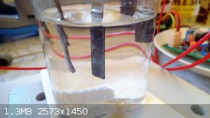
Fig.2 The cell with 50ml of electrolyte and the three electrodes suspended in it.
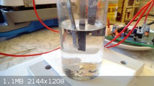
Fig. 3 One can see lead whiskers at the bottom of cell originating from cathodic overdeposition of lead during t1 period.
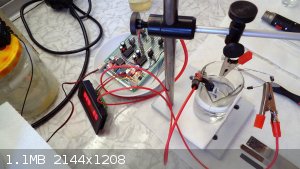
Fig.4 A more generic view of the setup (I apologize for the crude setting)
The deposition process was continued for 30 minutes under room temperature (21C) and at the aforementioned parameters. The electrodeposition of lead
dioxide at the central stainless substrate electrode started as different colored batches and stripes on the surface and the proceeded to take on a
dark, almost black glossy appearance over the entire submersed surface area of the central electrode surface. Gas evolution on central electrode was
minimal, but more pronounced during the first minutes and died down after that to only some bubbles sticking to electrode surface. These were removed
periodically, by lifting the electrode out of the cell momentarily and submersing it back in.
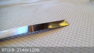
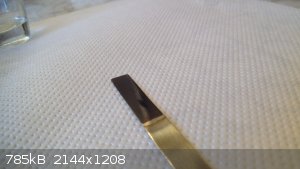
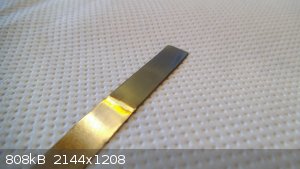
Fig. 5 The resulting lead dioxide layer on the central stainless substrate after 30min of deposition time
The resultant layer is of a bluish black coloration, has a glossy appearance and seems to be well adhered. At least visually what one could classify
as a most impressive result.
Closer observation under a USB microscope reveals that the sample is quite uniformly coated and seems intact.
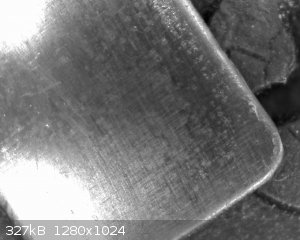
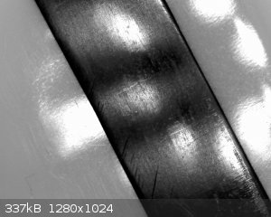
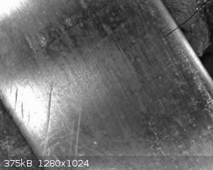
Fig. 6 The coating as seen under magnification of USB microscope
[Edited on 18-3-2018 by markx]
Exact science is a figment of imagination.......
|
|
|
markx
National Hazard
   
Posts: 645
Registered: 7-8-2003
Location: Northern kingdom
Member Is Offline
Mood: Very Jolly
|
|
Here one can observe the results of a "thicker" coating of presumably beta PbO2 that failed to adhere to substrate due to internal stresses that
develop during the layer formation process.
The layer was formed via the method described in previous post, but the plating conditions were altered as following:
t1/t2: 2/98
frequency: 10Hz
plating duration: 120min
current density: around 3mA/cm2
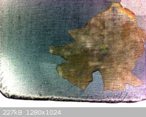
The higher freqency seems to allow for a thicker coating of PbO2 to form without stress cracking.
The coats formed at 2Hz frequency were subject to stress cracking only after 40min of electrodeposition vs. the same occuring at about 120min plating
duration at 10Hz.
Exact science is a figment of imagination.......
|
|
|
j_sum1
Administrator
       
Posts: 6218
Registered: 4-10-2014
Location: Unmoved
Member Is Offline
Mood: Organised
|
|
Surprised no one has commented yet markx. This is impressive work. If they test out ok under use then this is worthy of prepub. That finish looks
really tidy.
|
|
|
woelen
Super Administrator
        
Posts: 7976
Registered: 20-8-2005
Location: Netherlands
Member Is Offline
Mood: interested
|
|
At first when I read about this, I was thinking in the lines of "a difficult way to get some PbO2 on an electrode", but this setup actually really is
smart 
I myself have thought about similar things, but I always ended up with a 2-stage process. First taking a lead anode and a cathode of any material, and
pushing a lot of current through this, making the anode dissolve. You always lose some lead though on the cathode again. The second step then is
replacing the cathode by a fresh piece of material and using that as anode. That's a lot of plugging and hard to control.
In this setup you will finally get a certain fairly stable Pb(2+) concentration and deposition of lead on the cathode (rightmost electrode) and
deposition of PbO2 on the center electrode.
I am looking forward to see how the electrodes, made in this process, perform when used for electrolysis. If you can make some perchlorate from
chlorate with this setup, then that would be really interesting. Perchlorates are quite hard to make electrolytically and using the chlorate melting
method is quite risky, with risk of explosion or uncontrolled runaway and foaming of molten KClO3/KClO4. So, any progress in this direction is
welcome.
|
|
|
markx
National Hazard
   
Posts: 645
Registered: 7-8-2003
Location: Northern kingdom
Member Is Offline
Mood: Very Jolly
|
|
Quote: Originally posted by j_sum1  | | Surprised no one has commented yet markx. This is impressive work. If they test out ok under use then this is worthy of prepub. That finish looks
really tidy. |
Thanks for the kind words! 
It is a really facinating subject and has been haunting me for the longest time....there seems to be great potential in this approach and I try to
follow it to the extent that my abilities and resources allow me to.
To be honest, the current substrate material is not really the best option to choose for a functional and durable anode in agressive electrosynthesis
conditions (halide bearing solutions e.g.), but it allows me to study the effect of the parameters related to the "novel" electrodeposition process
and that in itself is quite satisfactory at the time.
I did test the small anodes in an improvised perchlorate cell containing relatively pure (carefully recristallised) KClO3 solution as the electrolyte
and to my amazement they held up for several hours of torture before I could see the iron starting to slowly dissolve from beneath the areas of most
current density and dicoluring the solution slightly yellow. The coating itself remained intact (did not discolor, deform or peel off in the cell).
But after removing the anode from perchlorate cell, flushing with water and wiping with a paper towel, the coating broke partly off in the most
afftected areas: corners, edges. A rather predictable outcome as the stainless steel corroded beneath the oxide and broke the adhesive bond.
In defence of this awaited failure I must say that these coatings used in the perchlorate cell were really thin: deposited during 15 and 30 min of
plating time in the lead cell and despite their fragile nature they still managed to hold up for far longer than I could have predicted.
A proper thicker coating will no doubt resist for far longer and perhaps even yield a working anode on a stainless substrate (now that would be
outstanding)....although I would preferably switch to titanium once the optimum plating conditions are worked out. This of course creates another
obstacle regarding the passivation blocking layer that need to be applied on a Ti substrate before PbO2 coating can be deposited, but prior art exists
and we all love a good challenge 
Exact science is a figment of imagination.......
|
|
|
markx
National Hazard
   
Posts: 645
Registered: 7-8-2003
Location: Northern kingdom
Member Is Offline
Mood: Very Jolly
|
|
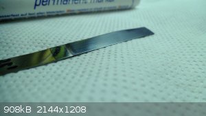
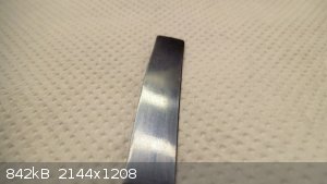
Here one can observe the formation of PbO2 forming through different colored deposit layers on the verge of the electrolyte contact point with the
stainless substrate:
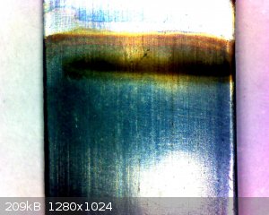
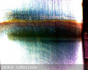
The upper part is the uncoated stainless substrate and lower part is unifrom layer of PbO2 formed on it at following conditions:
t1/t2: 2/98
frequency: 10Hz
deposition time: 60min
@ 21C electrolyte temperature
[Edited on 24-3-2018 by markx]
Exact science is a figment of imagination.......
|
|
|
markx
National Hazard
   
Posts: 645
Registered: 7-8-2003
Location: Northern kingdom
Member Is Offline
Mood: Very Jolly
|
|
The sample from last post happily bubbling away in a small perchlorate cell (KClO3 solution):
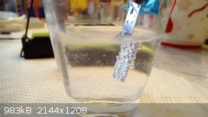
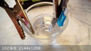
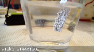
Unfortunately the coating is not perfect enough to shield the substrate metal and it starts to corrode after about two hours of operation.
Titanum still seems to be the only viable option for a durable anode of this type.
This brings me to the aforementioned obstacle regarding choices of passivation prevention coating for titanium....I guess the tin oxide option is one
of the most doable routes? Does anyone have any other reasonably simple options to suggest for this purpose?
I guess manganese oxide could also be one of the things to try....
Exact science is a figment of imagination.......
|
|
|
markx
National Hazard
   
Posts: 645
Registered: 7-8-2003
Location: Northern kingdom
Member Is Offline
Mood: Very Jolly
|
|
The result of trying to deposit PbO2 on a mechanically cleaned Ti substrate without an intermediate layer to counteract passivation:
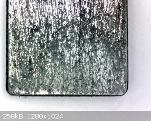
As can be seen the deposition is uneven and takes place on only the centers that passivated slow enough to allow for a conductive PbO2 layer to form
before the current flow ceased.
t1/t2: 2/98
frequency: 10Hz
deposition time: 35min
current density: unknown due to the passivated surface
electrolyte temperature: 21C
The blotchy layer is strongly adhered and can not be wiped off the surface.
You know what the weirdest part is.....this abomination actually conducts:
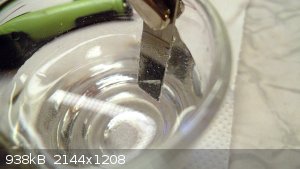 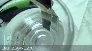
Going to see for how long though....
[Edited on 26-3-2018 by markx]
Exact science is a figment of imagination.......
|
|
|
markx
National Hazard
   
Posts: 645
Registered: 7-8-2003
Location: Northern kingdom
Member Is Offline
Mood: Very Jolly
|
|
As could be expected the Ti substrate anode is passivating at a rather progressive rate....
The initial current through the perchlorate cell was around 10mA
at 60min the current was 7mA
at 100min the current was 4,5mA
at 170min the current was 2mA
I project that around 200min the anode shall be passivated permanently....
[Edited on 26-3-2018 by markx]
Exact science is a figment of imagination.......
|
|
|
markx
National Hazard
   
Posts: 645
Registered: 7-8-2003
Location: Northern kingdom
Member Is Offline
Mood: Very Jolly
|
|
Yup.....I see a dead anode 
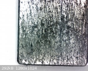
By 190min the current has fallen below 1mA and gas evolution has practically stopped on the surface.
The PbO2 layer looks quite identical to what it was in the beginning, but clearly the titanium substrate has passivated to a point where current can
no longer pass to the lead dioxide deposit.
Exact science is a figment of imagination.......
|
|
|
markx
National Hazard
   
Posts: 645
Registered: 7-8-2003
Location: Northern kingdom
Member Is Offline
Mood: Very Jolly
|
|
Here one can observe another interesting sample of lead dioxide deposition on "bare" Ti substrate:
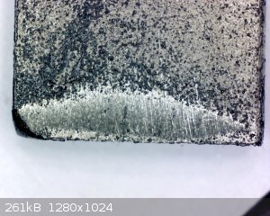
In this case I thoroughly sanded the lower edge of a Ti strip to clean metal and left the upper part as it was....under a deposit of years worth of
oxide. It was immediately placed into the PbO2 deposition bath under the same conditions as before:
t1/t2: 2/98
frequency: 10Hz
deposition time: 30min
electrolyte temperature: 21C
What is interesting is that most of the deposition centers occur in the pitting of the uncleaned and presumably thoroughly passivated upper part of
the strip and the abrasively cleaned lower part of Ti is virtually void of any deposit.
I find that highly intriguing.....does the titanium oxide layer under some favorable conditions create a preferred site for the deposition of lead
dioxide?
I also cleaned another strip of the same Ti stock thoroghly by sanding it completely to bare metal and placed it into the lead dioxide bath for
30min....virtually no deposition occurred on the surface.
Now look at the sample below:
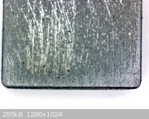
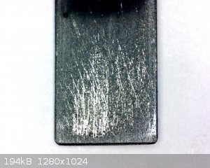
In an attempt to create a slightly oxidised surface favoring deposition, I thoroughly sanded this sample to bare metal and then electrochemically
etched it in ammonium heptamolybdate solution (30g/l) in alternating current mode of 50% anodic duty and 5Hz frequency for 20 min.
During that treatment the titanium first showed signs of passivation coloring, which appeared as different colored stripes of red, green and brown on
the surface. After about 5 minutes the surface of Ti turned a matte black and remained as such for the whole duration of the treatment. The black
layer was not adherent and could be wiped/washed off with some effort, revealing an ever so slightly beige colored surface.
In such state it was placed into the lead dioxide bath under the same conditions as previous Ti sample and at first it seemed to be passivated. After
10min it was apparent that deposition of PbO2 is taking place quite evenly over the entire submersed surface of the sample. There was an obvious
abundance of initial deposition centers compared to previous samples. The initially even deposition then progressed into an uneven one, favoring some
regions of the substrate, but still it was more uniform than in previous attempts. After 2 hours of deposition I ended up with the sample that can be
seen in the last pictures.
Exact science is a figment of imagination.......
|
|
|
markx
National Hazard
   
Posts: 645
Registered: 7-8-2003
Location: Northern kingdom
Member Is Offline
Mood: Very Jolly
|
|
Status update:
For practical purposes it seems I have solved at least the problem of creating a passivation blocking intermediate layer on Ti.
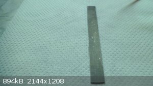
Fig. 1 Take a piece of raw Ti with desired dimensions and sand clean to expose bare metal surface
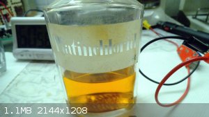
Fig. 2 Acquire chloroplatinic acid solution from convenient sources.
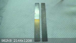
Fig. 3 Cover Ti substrate with chloroplatinic acid solution and heat carefully to 300-400C, obtain Pt clad titanium substrate.
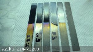
Fig. 5 Plate over with PbO2 at preferred conditions.
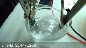
Fig. 6 Subject the anodes to torture in perchlorate cell conditions.
Exact science is a figment of imagination.......
|
|
|
j_sum1
Administrator
       
Posts: 6218
Registered: 4-10-2014
Location: Unmoved
Member Is Offline
Mood: Organised
|
|
Markx, I think you have made stunning progress here.
It would be great if you could write up the full procedure including electronics and put it in prepub.
|
|
|
markx
National Hazard
   
Posts: 645
Registered: 7-8-2003
Location: Northern kingdom
Member Is Offline
Mood: Very Jolly
|
|
Quote: Originally posted by j_sum1  | Markx, I think you have made stunning progress here.
It would be great if you could write up the full procedure including electronics and put it in prepub. |
I'm honored by the proposal 
But I would like to first work out a more or less working solution for this topic and then proceed to summarizing it in a compact form....
As far as current experimentation shows the PbO2 coatings deposited by the bath composition that I have used so far are not stable in the perchlorate
cell conditions. The coatings tend to deform and flake off from the surface of the anode.
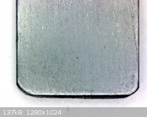
Fig. 1 Initial coating on Pt clad Ti substrate (60min deposition at 10Hz)
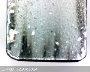 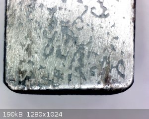
Fig. 2 Same coating after 30h in perchlorate cell conditions (facing away from cathode vs. facing to cathode respectively from left to right)
As one can clearly see the PbO2 coating is completely flaked off and rendered ineffective. The Pt clad substrate is still conductive and shows no
signs of passivation, which is a great succes in its own so far.
What is even better....the substrate can be chemically etched clean and reused to deposit a new coating.
To achieve that one has to immerse it into solution of citric acid+ammonium citrate+ acorbic acid for a few minutes. The proportions are not critical
and all of the PbO2 remnants shall be dissolved completely leaving the substrate unharmed and ready dor a new coating.
To combat the internal stresses and flaking of the coatings I decided to modify the deposition bath composition by adding 1g/l of Silipon RN 31
(sodium lauryl sulfate). This seems to have reduced the deposition rate of the PbO2, at least by visual assessment, but allows to deposit a uniform
and much thicker coating without developing stress cracking.
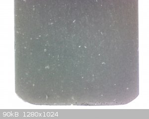 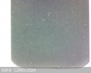 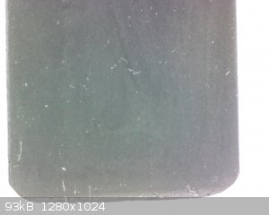
Fig. 3 Deposits on Pt clad Ti substrate from the Silipon modified bath at 60/120/180 min deposition time at 10Hz from left to right respecitvely
As can be seen the deposit is of a matte apperance as opposed to shiny and looks totally uniform without any stress cracking or other defects across
the entire surface. Pervious bath composition allowed for a maximum of 120 minutes of deposition before stress cracks appeared on the surfave of
coatings.
I also measured the deposition rate by weighing the sample after every hour ant the rate was pretty much constant at 20mg/h. Quite low, but if it
allows to build a stress free thick coating, then it might be the way to a durable anode.
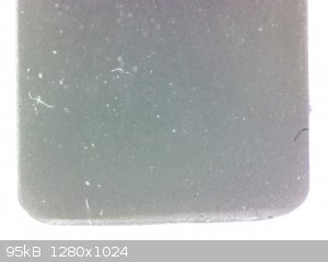
Fig. 4 Deposit at 240 minutes....still totally uniform and no cracking or defects (deposition rate holds constant at 20mg/h)
The white fibres that can be seen on surface originate from paper towel I use to dry the deposit after removing from deposition bath. They get snagged
on suface and can not be removed completly....also they seem to codeposit as can be seen on last image 
[Edited on 30-3-2018 by markx]
Exact science is a figment of imagination.......
|
|
|
markx
National Hazard
   
Posts: 645
Registered: 7-8-2003
Location: Northern kingdom
Member Is Offline
Mood: Very Jolly
|
|
The coating at 300 minutes. The corner broke off because I dropped it onto the floor  Makes a great illustration of the thickness though... Makes a great illustration of the thickness though...
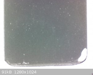
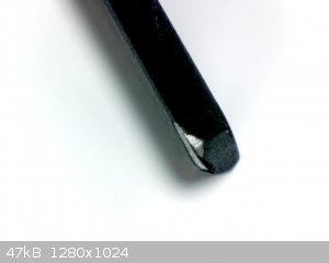
Exact science is a figment of imagination.......
|
|
|
| Pages:
1
..
40
41
42
43
44
..
47 |