| Pages:
1
..
41
42
43
44
45
..
47 |
markx
National Hazard

Posts: 645
Registered: 7-8-2003
Location: Northern kingdom
Member Is Offline
Mood: Very Jolly
|
|
360 minutes....all healed up 
Exact science is a figment of imagination.......
|
|
|
markx
National Hazard
Posts: 645
Registered: 7-8-2003
Location: Northern kingdom
Member Is Offline
Mood: Very Jolly
|
|
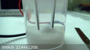
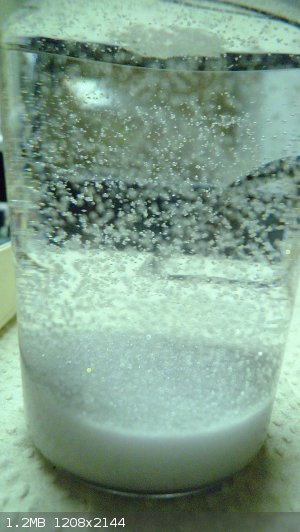
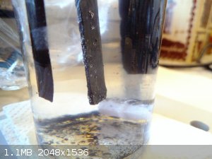
While I am waiting for my PbO2 layer to grow thicker I decided to experiment with just the bare Pt clad Ti substrate as the anode in a small
perchlorate cell:
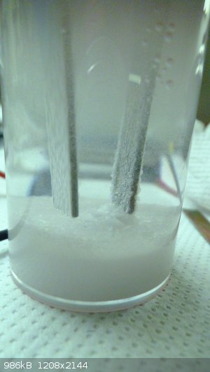 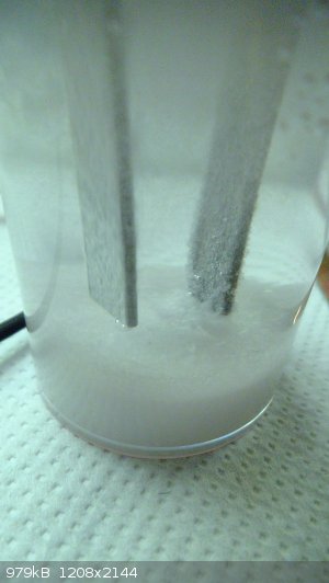
Anode is on the right side of the pictures. As one can observe there is magnificent potassium perchlorate formation taking place. It grows on the
anode as white layer of cristals and flakes off forming a nice pile under it. The thicker bottom layer is undissolved KClO3.
What was also interesting is that there was virtually no perchlorate formation visible on anode if the applied voltage was below 5V. There was current
passing the cell and vigorous gas evolution on both electrodes, but no visible perchlorate cristals on anode. Immedaiately after raising the cell
voltage to 5V or slightly above, there began a visible formation of KClO4 on the anode.
Quite interesting....I guess the anode was not polarized enough to permit the electrosynthesis of ClO4- at the lower voltages (4,5V) and concequently
also at lower current density?
That pile of KClO4 really is growing by the minute, constant visual percepitation is taking place around and on the anode.
There is 5,5V currently applied across the cell and 5,1W of power being consumed by the setup, which should bring us around 0,9A being passed (takeing
into account slight switching losses). The surface area of the anode is 5,6cm2 and that brings us to a current density of around 160mA/cm2, which
should be quite safe for a homemade Pt clad abomination 
[Edited on 1-4-2018 by markx]
Exact science is a figment of imagination.......
|
|
|
Diachrynic
Hazard to Others
Posts: 219
Registered: 23-9-2017
Location: western spiral arm of the galaxy
Member Is Offline
Mood: zenosyne
|
|
This is very exciting! I'm curious about your further experiments, markx. This is very very cool.
we apologize for the inconvenience
|
|
|
markx
National Hazard
Posts: 645
Registered: 7-8-2003
Location: Northern kingdom
Member Is Offline
Mood: Very Jolly
|
|
Short update:
I spent upwards of 14h growing the anode to a beefier state in terms of coating thickness and managed to deposit about 340mg of PbO2 from the SLS
modified bath:
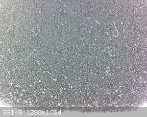
Fig. After 14h of deposition (slight dendritic formations visible)
The current density was doubled for the last 4 hours, but this resulted in dendritic growth as can be seen on the picture.
The coating was totally fine in terms of uniformity and lack of stress cracking after 14h of deposition time...looked really promising.
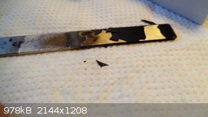
Fig. 2 After 20h in perchlorate cell. The coating is totally destroyed and flakes off in bulk.
Sigh....that was a disappointment, but at least I know now that it does not work this way. Time to introduce some changes and try again.
There seems to be a cristalline transformation taking place in the PbO2 coating under perchlorate cell conditions: a coating that is well adherent and
without defects seems to expand and develop huge compressive stress that deforms the layers and forces the coating to flake off in bulk. It does not
erode of dust off the anode, but instead peels off in deformed huge flakes.
The Pt clad substrate is totally fine, conductive and unharmed. I shall etch it clean and redeposit under different conditions.
After quite a bit of searching there seems to be mentioned in several sources that fluoride doped PbO2 offers better adhesion to substrates and also
deposits as a finer grained coat....
Exact science is a figment of imagination.......
|
|
|
markx
National Hazard
Posts: 645
Registered: 7-8-2003
Location: Northern kingdom
Member Is Offline
Mood: Very Jolly
|
|
I think that my deposition bath has become contaminated by all that experimentation and the possible additives in the technical grade lead that I use
as anodes (also the surfactants are for sure decomposing and altering the properties).
I do not seem to get the kind of dense start coatings I used to observe as the bath was fresh. Also there is a precipitate forming and last coatings
were pretty loose and of low density.
I trust there is a time for resetting the bath and starting with a new fresh filling.
Also I managed to dig up an old stock of strontium fluoride that I can possibly use as a plating additive for the fluoride doped deposit. It has quite
low solubility though, but the acidity of the bath composition should partly compensate for that shortcoming.
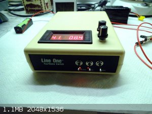
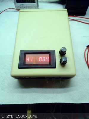
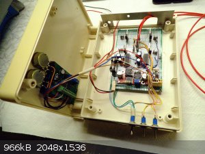
Also I really must find the time to incorporate the electronics of the H bridge into a manageable casing. The loose bundle of wires is really
interfering with my ability to concentrate on performing the experimentation
Exact science is a figment of imagination.......
|
|
|
markx
National Hazard
Posts: 645
Registered: 7-8-2003
Location: Northern kingdom
Member Is Offline
Mood: Very Jolly
|
|
A few shots of the KClO4 "stockpile" that I have managed to produce with the miniature cell during the tryouts ot the anodes and substrates so far
(perhaps in the range of 15-20g total):
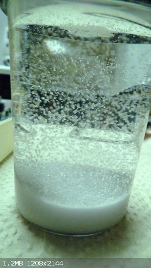
It looks very pretty and is inherently insoluble in water.....a rather strong indication that it is what it is claimed to be (omitting the chlorate
impurities)
I also tore down the barbaric H-bridge bundle and it shall be correctly incorporated into a proper casing:
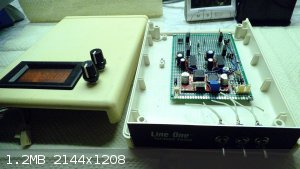
Now that looks already more like it
[Edited on 5-4-2018 by markx]
Exact science is a figment of imagination.......
|
|
|
markx
National Hazard
Posts: 645
Registered: 7-8-2003
Location: Northern kingdom
Member Is Offline
Mood: Very Jolly
|
|
Update:
I rigged the h-bridge system to a permanent DC voltage source (adjustable sepic converter) to be able to deposit for longer durations without messing
about with the Li cells after every hour....that part works well and can be left to function for days.
I also dumped the old bath and made a new one with the same composition:
200g/l Nh4NO3
40g/l HNO3
Silipon RN 31 SLS (0,5-1,0g/l)
Well....it deposits....nicely....but the internal stresses in the coating tend to deform and crack it if SLS content is below 1g/l and deposition time
goes over 240min.
I also tried to raise the bath acid content to much higher level (150g/l HNO3): that reduces deposition rate considerably and produces a highly
hydrophobic coating of PbO2, but still the internal stress remains.
Also none of the coatings tend to hold up in anodic perchlorate cell conditions for prolonged time (the Pt clad substrate is all that remains
operational after 24h of electrosynthesis).
I guess there is a combination that produces a durable coating, but so many variables to choose from....sigh...I do not even know which direction to
head to?
Leaning on the claims of several sources the internal stress situation has been conquered by depositing an initial alpha PbO2 layer from alkaline
plumbate bath and then proceeding to deposit an outer shell of beta PbO2 from acidic bath. A rather annoying extra procedure that defies my initial
goal of producing a coating with minimal effort and avoiding excessively unpleasant bath compositions. I will probably try it out though....
Another route would be to use different bath compositions in the single stage H-bridge driven setup. Theoretically any salt of an acid that has a
soluble lead counterpart can be used in the h-bridge setup (acetate, methanesulfonate, chlorate, iodide, tetrafluoborate etc.)
Yet another way would be to try out different plating additives that are known or can be suspected to have an influence on the coating stress
development (surfactants, dodecyl trimethyl ammonium type of compounds etc.)
Amazing how complex "simple" things can get in a heartbeat !
[Edited on 12-4-2018 by markx]
Exact science is a figment of imagination.......
|
|
|
Sulaiman
International Hazard
Posts: 3558
Registered: 8-2-2015
Location: 3rd rock from the sun
Member Is Offline
|
|
I'm just guessing here, but it seems to me that the root of your problem is the platinum.
If you an master plating with PbO2 then why not try less inert substrates ?
Lead sheet ?
CAUTION : Hobby Chemist, not Professional or even Amateur
|
|
|
markx
National Hazard
Posts: 645
Registered: 7-8-2003
Location: Northern kingdom
Member Is Offline
Mood: Very Jolly
|
|
Quote: Originally posted by Sulaiman  | I'm just guessing here, but it seems to me that the root of your problem is the platinum.
If you an master plating with PbO2 then why not try less inert substrates ?
Lead sheet ? |
Different substrate is an option. But eventually I would still like to grow the anode onto a Ti substrate...for perchlorate electrosynthesis this is
probably one of the best routes because of the inherent corrosion resistance of titanium (unfortunately that property also requires a passivation
proof coating undeneath the lead dioxide).
I did try stainless substrates in the beginning and although they produced very excellent thin coatings, the internal stress problem still remained.
Also I must mention that the stainless substrates also required electrolytic pretreatment to initiate a uniform and well adherent electrodeposition of
PbO2....namely they had to be coated with a blue interference layer in the ammonium molybdate bath under pulsed AC conditions.
Omitting that step would produce the formation of brightly colored PbO2 deposits (ranging from red to violet) which turned into loose brown flakes as
the coating thickened or even a black sooty deposit that could be wiped off the substrate.
The colored PbO2 deposit on untreated stainless substrate:
http://www.sciencemadness.org/talk/files.php?pid=510797&...
On wee bit brighter note we have this fugly monstrosity currently growing in the cell:
This weird coating formed on Pt clad Ti substrate as I let the high acid (150g/l HNO3) cell work despite the initial deformation and partial flaking
of coating. The picture shows resultant coating after 24h in the deposition cell under following conditions:
Frequency: 5Hz
t1/t2 : 1/99
temp: 21C
current density: 3-4mA/cm2
Apparently the initially deformed and flaked areas have grown over and a rather massive coat is forming. I currently did not see any cracking or
obvious deformations hinting to it as I pulled it out of the cell to incpect more closely. The coat has gathered some obvious volume over night and
looks very dense and smooth...almost shiny on microscopic level. But it is quite uneven....like a natural rock formation. There are no obvious
dendritic formations and the unevenness across the anode surface is totally random, not concentrated in just areas of obviously higher current
density. A weird mostrosity, I shall let it grow and see what comes out of this particular "mishap"
[Edited on 12-4-2018 by markx]
Exact science is a figment of imagination.......
|
|
|
Sulaiman
International Hazard
Posts: 3558
Registered: 8-2-2015
Location: 3rd rock from the sun
Member Is Offline
|
|
A new PbO2 anode video from AllChemystery
PbO2 onto a spinning carbon rod.
https://www.youtube.com/watch?v=tXSpqy2TNWo
[Edited on 12-4-2018 by Sulaiman]
CAUTION : Hobby Chemist, not Professional or even Amateur
|
|
|
markx
National Hazard
Posts: 645
Registered: 7-8-2003
Location: Northern kingdom
Member Is Offline
Mood: Very Jolly
|
|
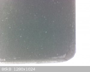
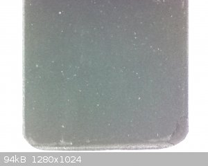
Update:
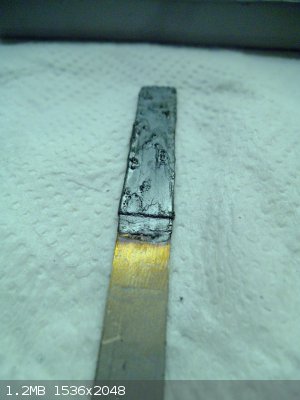
Fig. 1 General view of the "monstrosity" coating after 72h of deposition.
It is fugly, but rather massive and relatively compact. The mass of deposited coating is within error 2,2g.
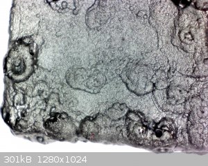 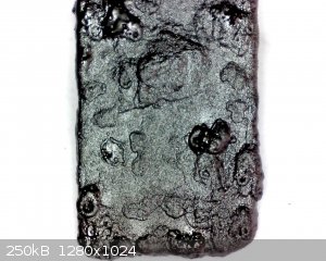
Fig. 2 The coating under magnification: quite extraordinary structure, it very much resembles a solidified mass of lava.
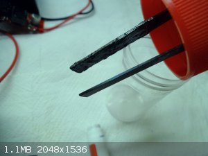 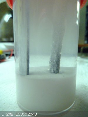
Fig. 3 Assembled to test cell and bubbling away under 5W of input power and 4,6V across the cell.
I see a uniform gas formation and no loose particles emanating from the anode after 15min of operation....somewhat of a good sign that it will not
break apart instantly, but lets see what happens overnight...
Exact science is a figment of imagination.......
|
|
|
markx
National Hazard
Posts: 645
Registered: 7-8-2003
Location: Northern kingdom
Member Is Offline
Mood: Very Jolly
|
|
Update:
The "monstrocity" coating was a failure. Alhough it seemed very promising during the first hours of operation, it still started to flake off and did
so in very bulky pieces during a rather short period. Again the only working component was the Pt clad sbstrate that remained.
I decided to give a try to depositing alpha lead dioxide from alkaline plumbate bath and acetate bath. See if that would work as an intermediate layer
between the Pt and beta oxide coat.
 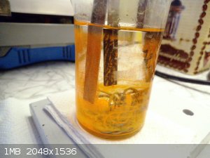 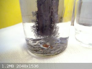
Fig.1 From left to right (alpha?)PbO2 coatings obtained from acetate bath, alkaline plumbate bath in operation, lead whiskers formed on acetate bath
cathode.
The acetate bath was simply 20% acetic acid solution into which Pb electrodes were submersed (Pt clad Ti as the center substrate electrode) and also
Pb strips at the bottom of beaker to enhance the soluble lead levels.
Bath was operated at 5Hz frequency and 97% anodic duty. Deposition onto Pt clad Ti substrate was very slow and partly the oxide coating formed as a
loose brownish dusty layer which could be wiped off. But underneath that loose layer there was a strongly adherent brownish coat. It was very thin,
almost translucent, as can be seen on the leftmost picture.
The samples on the picture conform to 24h and 72h of deposition time in the acetate bath.
The attempt at the plumbate bath was made by immersing lead strips in 5M NaOH solution in the hopes of driving at least some metal into the soluble
complex form (unfortunately no litharge was available). The reaction does occur, but it takes days to dissolve any appreciable amount of metal. In the
hope to speed up the reaction a small amount (about 2ml) of 30% hydrogen peroxide was added to the bath (80ml) dropwise and under stirring. That
brought about an immediate reaction which formed precipitate of lead oxides in the solution, confirming that some soluble lead complex had formed in
the bath. The lead oxide precipitate quickly redissolved in the alkaline conditions, but bubbling from the surface of lead metal at the bottom of the
beaker persisted for several days. After that a slow formation of Pb3O4 began in the beaker and it percipitated as a thin layer on the walls and
bottom of the cell. The liberally chosen amount of peroxide was probably too much. I trust the orange sediment on the second picture is quite obvious.
The formation of red lead oxide was slow and seemed to stop after a few days. Lead electrodes were immersed in the solution (Pt clad Ti as center
electrode) and the bath was set up to operate at 5Hz frequency and 97% anodic duty.
Contrary to the acetate bath a rather fast formation of a well adherent PbO2 layer began immediately on the center electrode. No visible gas formation
is observed, but the layer is clearly depositing....
[Edited on 25-4-2018 by markx]
Exact science is a figment of imagination.......
|
|
|
rolynd
Harmless
Posts: 16
Registered: 13-12-2004
Location: At Home
Member Is Offline
Mood: No Mood
|
|
ingenious setup for in situ generation!
your main problem though seems to be centered around
a) adhesion to substrate
b) internal stress/ductility of the coating
I have not tried to deposit PbO2 but maybe I have some insights into the stress/ductility issues that can be transferred to this problem .cant help
with the adhesion problem though,maybe proper undercoat and/or prep plays a big role here esp on titanium which is hard to get good adhesion on.
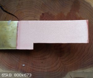
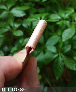
I have had very good success using a pulse/pulse reverse waveform regimen on thicker copper deposits to impart ductility. I used a arduino controlled
cheap h-bridge chip and set it to 10millisecond fwd(deposition) followed by 500microseconds(0,5milliseconds) reverse (deposit removal) . The resulting
copper deposit (about 0,5mm(500micron) on a brass strip was ductile enough that I could bend it 180° without cracking or separation from the brass
substrate. If I deposit the same thickness from the same bath under straight DC or single pulse the resulting deposit is much harder, it takes
considerably more force to bend the strip and the coating will crack at a bend of about 30° and separates from the brass substrate. so a simple
change from a straight or pulsed plating regimen to a pulse/pulse reverse waveform regimen was able to change the deposit quality profundly in terms
of ductility/internal stress. I cannot say if this can be transferred 1:1 to the deposition of Pb - this was copper after all - and lead may behave
differently. But as your 3 electrode setup is practically a pulse deposition vs a pulse/pulse reverse setup rearding deposition on the target anode I
think it would be worth a try. You probably will have to use a regular 2 electrode setup with lead salts already present in the solution though to
test this out.
brass strip with 0,5mm copper deposit ,pulse/pulse reverse waveform regimen
image1

the same, bent 180° without cracking or separation
image2

this is 0,5mm copper deposit from same bath but under single pulse . it started cracking at 30° bend and was then bent further to better show crack
and separation .same happens under straight dc conditions.
image3

the arduino and h-bridge chip used for that.
image4

It might well be that lead behaves differently than copper under those conditions and may require an adjustment to the specific timing of the used
waveform regimen - if you want to try this take my settings as a starting point and possibly experiment from there. Its just another idea to try
since you did use only pulse deposition so far and the effects on copper are clearly visible. I also attached a file I found on pulse reverse
electrodeposition of PbO2 electrodes which briefly covers this subject. good luck!
[Edited on 31-5-2018 by rolynd]
[Edited on 31-5-2018 by rolynd]
Attachment: JEAC_3835.pdf (1.7MB)
This file has been downloaded 537 times
|
|
|
mysteriusbhoice
Hazard to Others
Posts: 473
Registered: 27-1-2016
Member Is Offline
Mood: Became chemistry catboy Vtuber Nyaa
|
|
I have created relatively good graphite substrate PbO2 electrodes with brush electrolysis of lead acetate solution at 12v
I have experimented with 3v and 5v but the precipitant PbO2 would flake off and produce black gunk on the brush while it seems 12v produces a coating
which doesnt peel off in the abrasive brush electrolysis process.
Running the anode in an solution of sodium chlorate and sulfuric acid worked well.
The only con of this method is the extremely laborous process of RUB RUB RUB RUB RUB!!!!
edit:
im thinking of using sand/abrasive soaked with a bit of lead acetate with a rotating motor to consolidate a good coating that will be refined and
ensure that only PbO2 that adheres to the surface will stay on and all else will fall off the electrode while plating.
[Edited on 22-10-2019 by mysteriusbhoice]
|
|
|
markx
National Hazard
Posts: 645
Registered: 7-8-2003
Location: Northern kingdom
Member Is Offline
Mood: Very Jolly
|
|
| Quote: Originally posted by mysteriusbhoice | I have created relatively good graphite substrate PbO2 electrodes with brush electrolysis of lead acetate solution at 12v
I have experimented with 3v and 5v but the precipitant PbO2 would flake off and produce black gunk on the brush while it seems 12v produces a coating
which doesnt peel off in the abrasive brush electrolysis process.
Running the anode in an solution of sodium chlorate and sulfuric acid worked well.
The only con of this method is the extremely laborous process of RUB RUB RUB RUB RUB!!!!
edit:
im thinking of using sand/abrasive soaked with a bit of lead acetate with a rotating motor to consolidate a good coating that will be refined and
ensure that only PbO2 that adheres to the surface will stay on and all else will fall off the electrode while plating.
[Edited on 22-10-2019 by mysteriusbhoice] |
Very interesting results! So you basically brush plated with lead acetate solution onto a graphite substrate using a 12V dc supply? Any idea about the
thickness of the formed oxide coating? How long did you operate the anode in chlorate solution and did it you yield any perchlorate in the process?
I have not been able to produce a lead dioxide coat that could resist prolonged operation in chlorate solutions....although in sulfuric acid my
samples worked without any problems.
I kind of gave up on that venture and moved on to thermal platinum deposition. Apart from the dangers of having to deal with soluble platinum the
process does produce workable and scalable anodes that give good yields in perchlorate electrosynthesis.
Exact science is a figment of imagination.......
|
|
|
Σldritch
Hazard to Others
Posts: 309
Registered: 22-3-2016
Member Is Offline
Mood: No Mood
|
|
Really nice work markx, i was just wondering, did you try putting titanium at a negative potential to get rid of Titanium Dioxide? Seems so obvious
but i can't see that you mentioned it anywhere.
|
|
|
markx
National Hazard
Posts: 645
Registered: 7-8-2003
Location: Northern kingdom
Member Is Offline
Mood: Very Jolly
|
|
| Quote: Originally posted by Σldritch | | Really nice work markx, i was just wondering, did you try putting titanium at a negative potential to get rid of Titanium Dioxide? Seems so obvious
but i can't see that you mentioned it anywhere. |
As far as i’ve observed cathodic potential does not really reduce titanium dioxide back to nonexistance but merely changes the cristalline structure
into a state that is able to conduct charge under said potential. At least in aqueous solutions. Mechanical removal is quicker and more effective,
especially if the metal is coated under decades worth of reinforced scale.
Exact science is a figment of imagination.......
|
|
|
Σldritch
Hazard to Others
Posts: 309
Registered: 22-3-2016
Member Is Offline
Mood: No Mood
|
|
| Quote: Originally posted by markx |
As far as i’ve observed cathodic potential does not really reduce titanium dioxide back to nonexistance but merely changes the cristalline structure
into a state that is able to conduct charge under said potential. At least in aqueous solutions. Mechanical removal is quicker and more effective,
especially if the metal is coated under decades worth of reinforced scale. |
Interesting, but my thougths were more towards first doing mechanical removal and then putting it at negative potential for a moment to get rid of the
thin layer formed in the water. Maybe it would stick better, but there would also be a risk of lead forming which could nullify titaniums ability to
work as a valve metal. I can think of a bunch of more things that could happen but i do not want to indulge too much in speculation before i can try
it myself.
|
|
|
markx
National Hazard
Posts: 645
Registered: 7-8-2003
Location: Northern kingdom
Member Is Offline
Mood: Very Jolly
|
|
I deposited an intermediate Pt layer on Ti before the lead dioxide deposition process was applied. For all intentive purposes the ultrathin Pt layers
endured much better and outperformed any lead dioxide deposit that I’ve tried so far. I further pursued the approach and came up with a set of
parameters that would reproducably allow to create an inert anode capable of producing perchlorate at a very reasonable yield/cost ratio and having a
an acceptable lifetime of around 700h.
Exact science is a figment of imagination.......
|
|
|
nitro-genes
International Hazard
Posts: 1048
Registered: 5-4-2005
Member Is Offline
|
|
Only theoretical interest, wouldn't want any further trouble with the law...but...
US3294667A - Magnetite-stabilized lead anode
The patent basically deals with a lead anode that is said to be "stabilized" by a magnetite coating. The patent also mentions electrolysis of
saturated brine solutions with no visible corrosion of the anode. Such an anode could possibly be relatively easily made without any toxic soluble
lead salts needed. Just melting some lead metal (340 C) and stir in magnetite powder until it becomes a mouldable paste (magnetite should start to
oxidze further in air >400C).
Can't see directly how this stabilization would work chemically/physically. This is probably just to good to be true, anyone ever tried?
|
|
|
yobbo II
National Hazard
Posts: 709
Registered: 28-3-2016
Member Is Offline
Mood: No Mood
|
|
Magnetite can be used for making chlorate. It only makes perchlorate at 11% efficiency according to a patent. 11% is not that bad if the anode were to
last a long time.
...."For all intentive purposes the ultrathin Pt layers endured much better and outperformed any lead dioxide deposit that I’ve tried so far."...
Do you mean you used the platinum coated Ti on it's own (no lead dioxide) and it lasted longer than any other lead dioxide anode?
I think the way to go for perchlorate is pt bullion as per pinko or yob.
|
|
|
markx
National Hazard
Posts: 645
Registered: 7-8-2003
Location: Northern kingdom
Member Is Offline
Mood: Very Jolly
|
|
| Quote: Originally posted by yobbo II |
Magnetite can be used for making chlorate. It only makes perchlorate at 11% efficiency according to a patent. 11% is not that bad if the anode were to
last a long time.
...."For all intentive purposes the ultrathin Pt layers endured much better and outperformed any lead dioxide deposit that I’ve tried so far."...
Do you mean you used the platinum coated Ti on it's own (no lead dioxide) and it lasted longer than any other lead dioxide anode?
I think the way to go for perchlorate is pt bullion as per pinko or yob.
|
Correct....the oxide layers always fell apart and eroded away within the first 24h, exposing the Pt coat that remained operational for about 700h when
prepared at correct temperature. A solid bullion is of course the most foolproof solution, but the cost tends to be prohibitive. With the
hexacloroplatinic acid pyrolysis one can stretch a tremendous lifespan out of a minute quantity of Pt, so it was a win win for my purposes.
Exact science is a figment of imagination.......
|
|
|
nitro-genes
International Hazard
Posts: 1048
Registered: 5-4-2005
Member Is Offline
|
|
Just for fun I tried to produce graphite and graphite substrate lead dioxide anodes completely OTC... with some success. They are a lot of work
though, only suitable for miniature cells and compared to commercially available MMO anodes, Ti-substrate LD or platinum they probably suck, but that
was not main goal here. Anyway...here it goes:
A preweighed amount of a cyclohexanone/MEK based PVC cement was dried fully and then weighed again to determine the amount of low MW PVC polymer
present, and was found to be 25% by w/w..
Magnetite/hematite was made from steelwool that was burned thoroughly with a blowtorch until it fell apart easily. The result was a silver-grey powder
that after light crushing with a teaspoon in a bowl, consisted of small magnetite fibers.
To make the miniature anodes (70 mm long, 12 mm wide, 4-5 mm thick):
5 g finely powdered graphite powder (dry lubricant) was mixed with 0.56 g of the burned steelwool and 2.9 g of the PVC based glue (12% binder),
forming a soft clay-like consistency. While mixing occasionally, most of the volatile MEK was allowed to evaporate off until the consistency of
slightly wetted sand (seemingly loose powder, though sticks on compacting) was reached. The powder was then pushed into a mold made from a piece of
12mm thick plywood with a 70mm x 12 mm slot sawed out using a fretsaw. Baking paper was put into the mold to prevent anything from sticking and the
powder compacted using a hammer and another piece of 12 mm plywood as a dowel. The anodes were dried over the radiator for a week, until no more smell
of cyclohexanone was noticable. Depending on how far you let the cyclohexanone evaporate before hammering, binder percentage, and how hard you hammer,
the resulting resistance over the entire anode is 3-5 ohm. The burned steelwool is essential, without it the anode will form large cracks and weak
spots on drying, but too much and the resistance will increase. Despite the fact that these anodes are slightly porous by themselves they hardly erode
during sodium chloride electrolysis and they are not porous enough that he electrolyte will reach the connection to the anode itself, Mechanically
they are very strong and almost impossible to break by hand. When used in a 50 ml sat. sodium chloride cell at 3.5-4 volts will give about 0.3-0.4
Amps of current (<40 mA/cm2) and when chloride levels are kept high and cathode placing is right for even current distribution, they will go on for
a very, very, very long time as they erode only at an estimated 1 mg/ 10 amp hours or so.
One of these graphite/magnetite/PVC anodes was plated with roughly 1 mm of b-lead dioxide (25% lead nitrate, copper nitrate, pH of 1, 10mA/cm2 for
12h at 60 C. which seems to hold very well, probably due to the porosity of the anodes made this way (and perhaps the magnetite). The conductivity is
much higher after the lead dioxide coating, probably due to the lower resistance of the LD coating compared to the substrate anode itself. I'm
thinking the relatively high resistance of the graphite /magnetite/PVC anodes may be advantageous since (unlike highly dense graphite as a substrate)
almost all of the current will pass through the LD, leaving the substrate anode intact for longer. Sort of the middle ground between an inert ceramic
substrate anode (which is hard to coat evenly) and dense graphite substarte anode.
There is only one funny thing . The resulting LD anode was used in a 50 ml cell
with a 39% solution of sodium chlorate as electrolyte. Cell was run at 6V-0.9 A at a temperature of 40-45C with a stainless steel cathode. Strangely,
after 2 days of running the cell not a single mg of perchlorate had formed, while it is able to produce chlorate just fine.The anode has not shown any
kind of wear and seems to produce only oxygen.
What is going on here?! From what I have read fluoride additions are not requisite for complete conversion of chlorate to perchlorate, only increasing
current effiency. Things that I though of are:
- Is there maybe increased cathodic reduction going on due to the fact that I used salt with 100 mg/KG iodide added?
- Is the magnetite/presence or soluble iron in the electrolyte aiding to cathodic reduction?
- The lead nitrate was made by dissolving lead metal of unknown purity, could bismuth contamination or something screw up the LD anode for perchlorate
synthesis?
If the presence of iron and/or iodide in the electrolyte or a magnetite anode would be such a good catalyst for perchlorate reduction, might be of
some use in perchlorate removal from wastewater at least...
Anyway, any help would be appreciated. Any ideas why no perchlorate was formed?
[Edited on 17-4-2020 by nitro-genes]
|
|
|
markx
National Hazard
Posts: 645
Registered: 7-8-2003
Location: Northern kingdom
Member Is Offline
Mood: Very Jolly
|
|
You may want to keep on going with the electrolysis longer than 48h. In my experiments with Pt based anodes the formation of perchlorate was almost
always delayed by about 2 days. Sometimes a bit less, but 48h was about the rule of thumb for the starting point. I contributed the effect to Pt
surface needing a certain "preconditioning" period before it starts to yield perchlorate, but this might be a more generic effect not strictly bound
to the anode material.
Also by using a KClO3 solution instead of the sodium chlorate, one may visually observe the moment when effective perchlorate formation begins....the
product grows on the anode and flakes off continuosly. It is quite impressive to behold.
Exact science is a figment of imagination.......
|
|
|
nitro-genes
International Hazard
Posts: 1048
Registered: 5-4-2005
Member Is Offline
|
|
interesting comment on the reconditioning of the anode...
Not really any plans for the perchlorate myself, the physics and chemistry of these anodes is just fascinating, being able to oxidize chloride all the
way to perchlorate in solution! Yesterday I decided to crank the power all the way up in the perchlorate cell, and behold, today almost all chlorate
has been converted to perchlorate.
By rearranging the cathode position, the cell was run at 6V and 1.6 A, a current density close to the optimum of 0.22 A/cm2. More things changed
though. When freshly plated, the GSLD anode did not look a deep black as expected, but a plastic like, matt dark grey colour. After running the anode
very hard for 24 hours, the anode had turned to a deep black. Some stuff also seemed to have erroded away from the anode and covered the cathode with
a dark powdery coating that seems as conductive as the SS itself. I'm guessing lead metal itself, or maybe bismuth or antimony.
I couldn't find a "minimum voltage" for the Lead dioxide plating procedure, so I used about 1.6 V, maybe this was on the low side for LD plating?
Maybe some mixed lead(II)/Lead(IV) oxides plated along? Alternatively, maybe some bismuth oxides plated along with the lead dioxide itself. If this is
the case, the lead nitrate bath will probably produce better anodes the next time, since bismuth(III) would probably be plated first as compared to
lead(IV). Maybe worth looking at...would bismuth nitrate also plate into a conductive layer? Maybe not suitable for perchlorates, though maybe for
chlorates yes...
So...success! Though if it was the higher current density, the SS cathode being covered with lead/bismuth or the reconditioning of the anode still
needs to be worked out.
[Edited on 20-4-2020 by nitro-genes]
|
|
|
| Pages:
1
..
41
42
43
44
45
..
47 |


