ElizabethGreene
Hazard to Others

Posts: 141
Registered: 15-10-2012
Member Is Offline
Mood: No Mood
|
|
Construction of an inexpensive adjustable speed magnetic stirrer
Construction of an inexpensive adjustable speed magnetic stirrer
By Elizabeth Greene <Elizabeth.a.Greene@gmail.com>
Abstract:
This paper describes the construction of an inexpensive adjustable speed magnetic stirrer for use with a non-ferrous hotplate or oil bath. Design
decisions, Pitfalls, Schematics of the speed controller, and a bill of materials are included.
Action Shot:
<iframe sandbox width="420" height="315" src="//www.youtube-nocookie.com/embed/m9tMG6z5KPo?rel=0" frameborder="0"
allowfullscreen></iframe>
Description:
A rectangular magnet is attached to the top of an inexpensive double ball-bearing CPU fan. The fan is driven by a PWM motor speed controller and
powered by a 500 mW wall-wart power supply. JB-Weld adhesive is used to secure the magnet, and great care was taken to balance the assembly. A
square of non-skid padding is attached to the bottom of the stirrer to prevent it from vibrating off the workbench.
Design Decisions and Pitfalls:
This fan was specifically selected for its dual ball-bearing construction. The unit was originally constructed with a junk-drawer sleeve-bearing fan.
This unit failed very quickly.
The chosen fan is nominally rated for 3,000 rotations per minute. This speed would make the finished device unusable, sending both the stir bar and
solutions flying across the lab. A simple potentiometer was attempted for speed control, but the stirrer would not rotate at any speed with the
potentiometer connected.
Failing the simple speed control option, the second option was to use an Arduino to output a PWM signal to a simple motor driver circuit. The
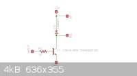
following circuit was built and tested on a breadboard.
Figure: Schematic of the dead-simple motor driver circuit.
To drive the circuit, the Arduino AnalogWrite function was used. See http://arduino.cc/en/Reference/AnalogWrite. Permanently dedicating an Arduino microcontroller to this project violates the “Low-Cost”
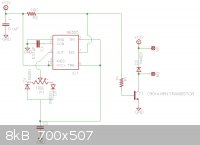
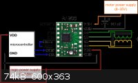
objective of this project. Additionally, the movers broke my Arduino touch screen shield.  A third option, a dedicated PWM generator, was designed, tested, and built. A third option, a dedicated PWM generator, was designed, tested, and built.
Figure: A low-cost PWM DM motor speed control circuit
An Altoids tin was selected as a project enclosure. This was lined with duct-tape to prevent shorting out the controller. Any container of suitable
size would suffice, but the likelihood of exposure to heat and chemical spills suggests the use of a metal enclosure.
Cyanoacrylate “Super-Glue” adhesive was tried as the adhesive for the fan-to-drive-magnet junction. This failed repeatedly during testing. The
first failure was at approximately 75% speed, impacting the wall behind the workbench. After reattaching, the magnet snapped off when the stirrer was
accidentally dropped onto a wooden workbench. Hot-Glue was discarded as an option due to heat and chemical compatibility. Roughing the surface of
the drive magnet and fan with 80-grit sandpaper and securing the magnet with JB-Weld adhesive provides a satisfactory solution.
The magnet must be centered very carefully on the fan to prevent excessive vibration. This is a painstaking process, and the JB-Weld allows plenty of
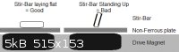
time to make final adjustments. Before applying the adhesive, use a stir-bar to verify the magnet’s polarity. Improper orientation will cause the
stir-bar to stand on end.
An attempt to use two magnets for greater magnetic flux was made, but this was too much load on the fan bearings. It would not rotate at low speeds.
Self-Criticism:
The author has assumed there is a fuse built-in to the wall-wart power supply. This is a foolish and unsafe assumption, and a discrete fuse will be
added.
The author’s electronics skills are very limited, and skill in drawing schematics even more so. Those attempting construction of this project are
strongly recommended to breadboard the circuits before construction.
Bill of Baterials:
Note: Radio-Shack part numbers are included in parenthesis below, but other vendors may be significantly less expensive. Excluding the Fan, Magnet,
and 12V power brick, all of the electronic components to breadboard this project are included in the Radio Shack “Electronics Learning Lab” Kit.
• Inland brand “80mm Performance Fan”. (Micro-Center $2.99 http://www.microcenter.com/product/381171/80mm_Dual_Ball_Bea... )
• Magnet Source 3/8” x 7/8” x 1 7/8“ Permanent Ceramic Magnet (MagnetSource.com CB60N)
• JB-Weld Adhesive (Home Depot)
• 12 volt 500 mA wall-wart power supply (#273-357)
• NE555 timer IC (#276-1723)
• 1 NPN Transistor (#276-1617)
• 3 1N4001 Diodes (# 276-1653)
• 2 0.1uF Ceramic capacitors (#55047557)
• 1 0.01uF Ceramic capacitor (#55047551)
• 1 10K Ohm resistor (#271-306 assortment Pack)
• 1 1K Ohm resistor (Included in above assortment)
To permanently construct the motor controller off the breadboard, the following additional components are required.
• Altoids tin or other project enclosure
• Printed circuit board or perfboard (#276-148)
• 100K ohm potentiometer (#271-092)
• SPST toggle switch (#275-324)
• Solder, soldering iron, & hookup wire.
• Non-Slip drawer liner for “feet” (Source unknown)
Suggestions for Future Work:
A motor is a series of electromagnets energized in such a way to make a magnetic rotor rotate. It seems rube-goldbergian to physically attach this
apparatus to a magnet for the purposes of rotating a third magnet. A more efficient design would use a number of electromagnet coils turned on and
off in the correct sequence cause the stir bar to rotate. This apparatus could be physically constructed in a relatively inert substance like glass
or ceramic to make a silent and vibration free stir-plate or stir-hockey-puck. It may be possible to adapt a stepper-motor controller IC for the
difficult work of generating the correct polarity, sequence, and timing for this apparatus. To the author’s dismay, a patent search found an
example of this idea in patent 3554497 and a number of similar products on the market.
A larger drive current could be used safely by limiting the PWM duty cycle. This would allow significantly higher starting and low-speed torque.
A humming sound can be heard when the device is in use, particularly at low speeds. Increasing the frequency of the PWM drive to > 20kHz should
shift this humming sound out of the range of human hearing.
With the addition of another drive transistor, a second fan/magnet could be added to agitate large solutions or an oil bath.
References:
Simple PWM DC Motor Driver Circuit
http://letsmakerobots.com/files/userpics/u4383/simple_dc_mot...
NE555 PWM Motor Controller Circuit
http://homemadecircuitsandschematics.blogspot.com
Homemade Show: 2$ Magnetic Stirrer Tutorial
http://www.youtube.com/watch?v=Ak2a_WLZD-E
[Edited on 24-7-2013 by ElizabethGreene]
|
|
|
annaandherdad
Hazard to Others
Posts: 387
Registered: 17-9-2011
Member Is Offline
Mood: No Mood
|
|
Thanks, Elizabeth, I've been thinking about exactly this problem myself (how to make your own magnetic stirrer for cheap), and you've done all the
research for me.
Any other SF Bay chemists?
|
|
|
bfesser
|
Thread Moved
23-7-2013 at 16:59 |
bfesser
Resident Wikipedian
Posts: 2114
Registered: 29-1-2008
Member Is Offline
Mood: No Mood
|
|
<strong>ElizabethGreene</strong>, this is another excellent write up; I hope you don't mind that I moved it to
<strong>Prepublication</strong>.
I have a few short suggestions and comments:
I agree that an Arduino would be overkill; it's always nice to see a 555 in use!
I have a can of <a href="http://www.homedepot.com/p/Spray-Liquid-Tape-in-Black-6-oz-Can-6-Cans-Master-LTS-400/202906380#.Ue8zlY21H8Y"
target="_blank">"spray liquid electrical tape,"</a> <img src="../scipics/_ext.png" /> I wonder if this would be a good way to insulate
the inside of an Altoids tin. I'll try it and report back.
I like your idea of using a stepper motor driver to drive a stirrer of no moving parts. I had one of these stirrers, produced by <a
href="http://www.ika.com/owa/ika/catalog.product_detail?iProduct=3907500&iCS=1&iProductgroup=188&iSubgroup=1"
target="_blank">IKA</a> <img src="../scipics/_ext.png" />, but it unexpectedly died. One downside of these stirrers is serviceability.
It would be great if you would pursue the stepper driver idea.
I noticed the minor typographic error below: I look forward to reading your next paper. Keep up the good
work!
[Edited on 7/24/13 by bfesser]
|
|
|
ElizabethGreene
Hazard to Others
Posts: 141
Registered: 15-10-2012
Member Is Offline
Mood: No Mood
|
|
bfesser:
Thanks for the correction, I edited the post. For the solid state stirrer, I'm thinking about a 555 timer pulse generator...
(Courtesy of the Forest Mimms engineer mini-notebook)
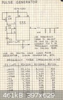
With the output over to the input of one of these Pololu stepper motor drivers. http://www.pololu.com/catalog/product/1182
 At $9.95, they aren't cheap, but it does 99% of the work for this project. At $9.95, they aren't cheap, but it does 99% of the work for this project.
The part I don't understand is winding the coils for the drive electromagnets. From reading How Stepper Motors work I get that the up and down windings go in series and the left and right go in series. I've even got the basics of the
mechanical assembly sorted out. Four bolts (steel) driven into a carrier (wood or aluminium) with the heads hacksawed off.
What I don't know is "How many turns of what gauge wire" to make the coils. I'll either have to learn more about that or determine a valid
combination experimentally.
... FWIW, I'm working on emptying another Tin of Altoids.
|
|
|
watson.fawkes
International Hazard
Posts: 2793
Registered: 16-8-2008
Member Is Offline
Mood: No Mood
|
|
No need for that. Just buy empty ones: http://www.specialtybottle.com/tinrectangular39by245hinged.aspx. Unless, you need the sugar.
Same company has lots of other sizes of tins. They also have amber bottles, etc.
|
|
|
Organikum
resurrected
Posts: 2329
Registered: 12-10-2002
Location: Europe
Member Is Offline
Mood: busy and in love
|
|
The professional lab stirrers I opened all used split pole motors, I guess there might be good reason for this, The basic characteristics make such a
motor a good choice, in special the torque and the more elastic coupling to the magnetic field not to overrun the stirbar.
These motors come for free in every microwave which come for free everywhere. The drive the fan often there are even two of them.
Solid state stirrers are not trivial, I own an early adaption of the system and it is not really good (except that it can be used underwater). Driven
by square wave with four coils it is jerky and so tends to throw the stirbar in the corner, nevertheless it is not powerful enough when it gets
viscous.
You need more then 4 coils and/or ramped up power (or sinus) to drive the coils. Thats whats in the patents and articles about the matter. Together
with a feedback circuit and variable coil drive an arduino would not be wasted on such a project.
/ORG
|
|
|
bbartlog
International Hazard
Posts: 1139
Registered: 27-8-2009
Location: Unmoored in time
Member Is Offline
Mood: No Mood
|
|
I might try to build this. My electronic skills are if anything even more limited than yours and this would be a nice starter project. Thanks for the
writeup!
The less you bet, the more you lose when you win.
|
|
|
ElizabethGreene
Hazard to Others
Posts: 141
Registered: 15-10-2012
Member Is Offline
Mood: No Mood
|
|
Organikum:
"Tends to throw the stir bar in the corner" - Could you explain this a different way? Is it unbalancing the stir bar in such a way as to throw it off
the stir area completely?
When I graphed out what the power flow should look like on paper I came up with a sine wave for one pair of coils and a cosine wave for the
perpendicular set. Unfortunately, when I looked for a simple variable frequency sine wave generator they all required variable capacitors or other
fiddly bits. Those variable capacitors are not in my toolbox, and dual ones are rare as hen's teeth. That means we are off in microcontroller land.
A PIC and an L298 driver meet the "Cheap" requirement, and are on my brainstorming sheet. This is largely due to my acquisition of a Radio shack PIC
programmer soldering kit on clearance for $15. 
Another thing I'm considering is intuiting the position of the stir bar based on the magnetic field. That could feedback to the mcu to let it know if
a step was missed. I'd be lying if I said I completely understood the maths or the electronics behind that.
Off to home depot! 
|
|
|
enhzflep
Hazard to Others
Posts: 217
Registered: 9-4-2006
Member Is Offline
Mood: No Mood
|
|
Fantastic project and write-up ElizabethGreene. :thumbs-up:
I've considered something like this on and off for a while now. While it still wouldn't be as cheap as a 555 timer, you can buy arduino _very_ cheap
on ebay.
I'm tempted to make something based from your project using one of these. The advantage, of course is (a) the easy ability to monitor the hall-effect
sensor in the fan (yellow wire) to have precise stirring RPM, also to have stirring profiles which allow for the rate of stirring to change over time.
Perhaps there could be utility in adding a start/stop timer. Another use could be to wait until the solution had reached a pre-determined
tempterature.
Anyway, I've bought these units, delivered, for about $4.50 to australia from china. They work an absolute treat. A 128x160 262k color screen can be
had for peanuts too (a hair over $5)
I apologise if this isn't really seen as appropriate or constructive. I'm still flabbergasted at the price differential between genuinue arduinos,
locally sourced clones and ebay specials. Hope someone else finds utility for this info. It's certainly brought me much joy.
Arduino Pro Mini 5v 16Mhz (US $2.84 + delivery)
http://www.ebay.com/itm/190840405723
1.8" SPI interface LCD screen inc SD card socket (US $2.66 + delivery)
http://www.ebay.com/itm/200917828584
|
|
|
annaandherdad
Hazard to Others
Posts: 387
Registered: 17-9-2011
Member Is Offline
Mood: No Mood
|
|
Sometimes a project like this is worth doing just for what one would learn by doing it. Some of the people on SM are quite sophisticated when it
comes to building equipment like this, but I'm not one of them. Still, I'm sure I could learn as I go. Another important factor for me is that i'm
working with some young people, and they would learn as much or more than I would. For these purposes the cost isn't so important, and, although I'm
put off by the cost of commercial heaters/stirrers, I'd be willing to spend more money making one of my own if the educational value were enough.
Any other SF Bay chemists?
|
|
|
smaerd
International Hazard
Posts: 1262
Registered: 23-1-2010
Member Is Offline
Mood: hmm...
|
|
Very nice elizabethgreene
When I made one of these I had major balancing issues and scrapped the project only to buy a used model later. Nice to see that you got it to work
though.
|
|
|
kmno4
International Hazard
Posts: 1495
Registered: 1-6-2005
Location: Silly, stupid country
Member Is Offline
Mood: No Mood
|
|
Slightly forgotten thread about DIY stirrers:
http://www.sciencemadness.org/talk/viewthread.php?tid=3056&a...
Слава Україні !
Героям слава !
|
|
|
papaya
National Hazard
Posts: 615
Registered: 4-4-2013
Member Is Offline
Mood: reactive
|
|
Quote: Originally posted by ElizabethGreene  | Organikum:
When I graphed out what the power flow should look like on paper I came up with a sine wave for one pair of coils and a cosine wave for the
perpendicular set. Unfortunately, when I looked for a simple variable frequency sine wave generator they all required variable capacitors or other
fiddly bits. Those variable capacitors are not in my toolbox, and dual ones are rare as hen's teeth. That means we are off in microcontroller land.
|
Why not take a 50/60Hz sine wave from your socket, and placing a capacitor in parallel to the other winding to get the phase shift up to cosine ?
Speed will be uncontrollable, but if that works... Or you take a huge synchronous motor with already adjusted capacitors, etc, take out rotor and put
your flask inside 
|
|
|


