bob800
Hazard to Others

Posts: 240
Registered: 28-7-2010
Member Is Offline
Mood: No Mood
|
|
necessity of isolation transformers
I asked this question on a dedicated electronics forum, though it was somehow "off limits" so I didn't receive any useful responses. Somehow I doubt
that will be the case here  . .
I'm planning on building a solid-state tesla coil as described here, but the author does not describe his 150V power supply (the one on the drain of the IRFP450).
Would it be safe to assume that he simply used rectified mains power? I have a 800V 35A bridge rectifier which I could connect to a variac to adjust
the DC voltage to 150V.
Or would this be too dangerous without an isolation transformer? Would it damage my oscilloscope if I connected it to the unisolated section?
|
|
|
Metacelsus
International Hazard
Posts: 2531
Registered: 26-12-2012
Location: Boston, MA
Member Is Offline
Mood: Double, double, toil and trouble
|
|
I have driven an IRFP450 off the rectified output from variac without any trouble. However, I was using 45 VDS and had a 25 kHz, 92.5% duty
cycle square wave driving the gate. The average power was 500 W. (This was for a flyback driver.)
[Edited on 20-12-2013 by Cheddite Cheese]
|
|
|
WGTR
National Hazard
Posts: 971
Registered: 29-9-2013
Location: Online
Member Is Offline
Mood: Outline
|
|
Let me share a short story.
Many years ago I built this rather nice oscillator using vacuum tubes. Instead of using a big, bulky, transformer; I
thought, "Hey, why do I need a transformer for power? I can just hook a bridge rectifier right across the 120VAC from the
wall, and get about 170VDC out of it."
Feeling really smart, I did exactly that, thinking that I had solved an age-old problem with filtering half-wave-rectified
power.
Everything powered up just fine; I hooked up the antenna...and then I hooked up the ground wire. I never really found the top
half of the bridge, but what was left of the bottom half consisted of fused silicon. I had to sit and think for a bit before
I could figure out why that had happened.
The neutral line in the house was grounded. I grounded one of the outputs of the bridge. This essentially shorted out one of
the diodes in the bridge, and dumped full line current through another. The results were nothing short of spectacular.
In conclusion, I wouldn't advise using a bridge rectifier without an isolation transformer. You can always put two 12V
transformers back-to-back to provide isolation, if you don't have a direct 1:1 transformer.
|
|
|
bob800
Hazard to Others
Posts: 240
Registered: 28-7-2010
Member Is Offline
Mood: No Mood
|
|
 I hope none of your vacuum tubes were damaged! I hope none of your vacuum tubes were damaged!
Thanks for the replies--I think I'll cut open my 2 MOTs and place both primary coils in one of them.
|
|
|
IrC
International Hazard
Posts: 2710
Registered: 7-3-2005
Location: Eureka
Member Is Offline
Mood: Discovering
|
|
Draw out the circuit showing 4 diodes and their connection. It will be clear why the bridge will blow. Isolation must be used for a bridge circuit on
the AC line. In fact since the circuit ground is common to the line I think isolation should be used for the sake of safety anyway. The scope will be
fine with the probe ground on earth or neutral and the tip on whatever it is you are measuring relative to neutral.
Big isolation transformers are heavy and costly but needed for a high power circuit using a bridge and you would be much safer running the coil.
Having the circuit ground lethally hot relative to earth is never a good idea. All those old TV's sans power transformer had the chassis isolated in
the plastic cabinet with all knobs insulated as well. Touching the chassis inside would toss you across the room as well as potentially being lethal.
Also you should consider in a line powered device the outlet you are going to plug into. I have seen so many with line and neutral being reversed,
ground being disconnected and other nightmare variations. Meaning test your outlet to know it is properly wired before plugging your coil in.
"Science is the belief in the ignorance of the experts" Richard Feynman
|
|
|
quantumchromodynamics
Hazard to Self
Posts: 67
Registered: 25-9-2013
Location: with much determination, nowhere in particluar
Member Is Offline
Mood: tired but still trying
|
|
it can work quite well
If you design the tank properly; by this I mean a composition of a monster electrolytic, some poly prop, and some tantalum, and some TVSs, and Zeners,
one can build a very nice smooth low pass tank. One trick is to mount the IGBTs right on top of the caps with absolutely minimal connection length.
Use big flat copper plates if you can. A half wave rectifier will work fine and you don't need isolation transformers or line filters or anything.
Some people go nuts with isolation transformers, protection filters, terry filters, etc. I have found that if you spend the time and build a good tank
and a well tuned coil prophylactics are not necessary. Please realize, it is very time consuming and quite an job to get a coil running at best
efficiency. Most folks simply get some arcs going. When a coil is in tune very little noise feeds back into the power system. Always current limit the
line power with a big fat resistor. A word of advice, when working on such things, throw a fuse into the tank circuit. Fuses are cheaper than IGTBs.
Also, IRFP450s are not very good IGBTs. Cheaper faster better IGBTs exist.
|
|
|
IrC
International Hazard
Posts: 2710
Registered: 7-3-2005
Location: Eureka
Member Is Offline
Mood: Discovering
|
|
Quote: Originally posted by quantumchromodynamics  | | If you design the tank properly; by this I mean a composition of a monster electrolytic, some poly prop, and some tantalum, and some TVSs, and Zeners,
one can build a very nice smooth low pass tank. One trick is to mount the IGBTs right on top of the caps with absolutely minimal connection length.
Use big flat copper plates if you can. A half wave rectifier will work fine and you don't need isolation transformers or line filters or anything.
Some people go nuts with isolation transformers, protection filters, terry filters, etc. I have found that if you spend the time and build a good tank
and a well tuned coil prophylactics are not necessary. Please realize, it is very time consuming and quite an job to get a coil running at best
efficiency. Most folks simply get some arcs going. When a coil is in tune very little noise feeds back into the power system. Always current limit the
line power with a big fat resistor. A word of advice, when working on such things, throw a fuse into the tank circuit. Fuses are cheaper than IGTBs.
Also, IRFP450s are not very good IGBTs. Cheaper faster better IGBTs exist. |
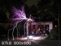
quantumchromodynamics, Quite frankly I am astounded by the level of gibberish you posted. Yes indeed monster electrolytics are exactly what you want
in the 'tank circuit', an LC circuit oscillating at radio frequencies. Yes indeed blow off the isolation and by all means pay no attention to the
polarity of your line cord with your entire circuit ground to the coil connected to one side of the AC mains. Not. Some of us just don't know jack
about building Tesla coils even if the pic below is mine more than a quarter of a century ago. No need indeed to listen to my advice.
"Science is the belief in the ignorance of the experts" Richard Feynman
|
|
|
WGTR
National Hazard
Posts: 971
Registered: 29-9-2013
Location: Online
Member Is Offline
Mood: Outline
|
|
Certainly, quantumchromodynamics , you can get by with an unisolated half-wave rectifier, but you have
to be sure that your hot and neutral wires aren't switched. A lot of the old AC/DC tube radios played this rather
dangerous game, and sometimes you'd get a buzz if you touched the cabinet. It's not very safe. Really, if one
has a couple of 120V:12V step-down transformers laying around, just connect them back to back (step-down to
step-up). It will work as long as they can handle the power, and are truly isolated (primary not connected
to secondary).
Yes, bob800, the tubes were fine.
|
|
|
Marvin
National Hazard
Posts: 995
Registered: 13-10-2002
Member Is Offline
Mood: No Mood
|
|
It's woefully bad advice, best ignored, but it's not gibberish. He's talking about SSTCs so by "tank" he clearly means reservoir-switch-primary
circuit which in a spark gap coil (operating differently to an SSTC) would be the tank.
Awesome coil IrC.
|
|
|
IrC
International Hazard
Posts: 2710
Registered: 7-3-2005
Location: Eureka
Member Is Offline
Mood: Discovering
|
|
I knew he meant a reservoir of stored charge Marvin, no doubt your right about that. Yet the use of terminology was careless. In electronics a 'tank'
has specific meaning. Also he irritated me by so cavalierly telling another member to forgo safety concerns when in an online forum none of us know
the level of competency of any other members (or any readers passing by). Historically SCM has lost at least one member I know of (phosgene), and
possibly others who thought they were invulnerable masters of the sciences. You just never know. In the pic I was operating the coil at around 20
percent power. Later on that night I had a 240 V input 5 KVA Variac go up in flames at around 37 percent power. I ended up using a Lincoln Arc welder
as a variable core reactor from then on to feed my two pole Pigs. To this day I still feel sad about that Variac it was the best one I ever owned and
it was costly.
Thanks for the compliment. Believe it or not it only took under 3 hours to wind that 6" PVC pipe with Litz wire for a length of 5 feet. I perfected my
method of winding giant coils by hand using a rotating arbor mounted on two saw horses.
I built an extra coil about 3 feet in diameter which you can see on the ground by the front door which I later mounted in the air connected to the top
of the Tesla coil. Took a while to wind that one.
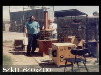
If you look closely at the front of the box (chair in front) you can see where my now DOA Variac used to mount. The guy in the white shirt is Robert
Golka which you have probably seen on some old Nova show about Project Tesla, but that is another story. Right behind that box is a bank of three 0.02
uF 120,000 volt Plastic capacitors mounted on Plexiglass supports.
[Edited on 12-20-2013 by IrC]
"Science is the belief in the ignorance of the experts" Richard Feynman
|
|
|
quantumchromodynamics
Hazard to Self
Posts: 67
Registered: 25-9-2013
Location: with much determination, nowhere in particluar
Member Is Offline
Mood: tired but still trying
|
|
stop blabbering...
and learn some electronics...
[Edited on 21-12-2013 by quantumchromodynamics]
|
|
|
IrC
International Hazard
Posts: 2710
Registered: 7-3-2005
Location: Eureka
Member Is Offline
Mood: Discovering
|
|
Hopefully you will not end up getting Polverone sued when your cavalier anti safety advise to members causes someone to be injured.
Longer sparks does not prove you know more electronics. It merely means your coupling factor K was lower creating greater resonant rise since sparks
was your goal. Around 0.04 to 0.06 looking at your pictures. Mine was 0.12 to 0.16 because I was actually experimenting with broadcasting power
requiring greater energy transfer between primary and secondary. If you studied Tesla you would realize he went to great lengths to minimize sparks
because broadcasting power was his goal.
My comments about K were made assuming the coil is at resonance. With looser coupling the BW is lower (sharper resonance peak) thus allowing greater
resonant rise. Tighter coupling widens the bandwidth due to the corresponding increase in the number of modes allowed to exist simultaneously. However
not enough power is driven into the secondary with loose coupling to yield a large amount of broadcast power. If you read Tesla's Colorado Springs
notes you will see where he could stick lights into the ground at ever increasing distances, lighting them, as he increased the K factor while doing
everything he could to eliminate sparks forming. Sparks coming off the top of the coil result in a circulating current (between coil and ground) which
effectively rob most of the energy being broadcast.
Tesla in his own words considered production of sparks a failure resulting in his going back and reworking the system to eliminate the problem. In
short Teslas goal was broadcast power not a lightning display. My goal was the same.
[Edited on 12-21-2013 by IrC]
"Science is the belief in the ignorance of the experts" Richard Feynman
|
|
|
quantumchromodynamics
Hazard to Self
Posts: 67
Registered: 25-9-2013
Location: with much determination, nowhere in particluar
Member Is Offline
Mood: tired but still trying
|
|
a question about an isolation transformer
A little bitty chopper type DC coil does not need an isolation transformer to be safe.
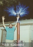
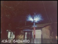
What long arcs do show is a coil that is in tune. This coil is tuned to run with a single ground striking leader. Think weapons application...
Tesla is my freaking hero. There is more to tuning a coil than most folks realize. Tesla was quite the expert.
I apologize to the board for being upset.
Science!
|
|
|
Marvin
National Hazard
Posts: 995
Registered: 13-10-2002
Member Is Offline
Mood: No Mood
|
|
Your coil is another awesome demonstration of electrical engineering. But spark gap driven equipment does not speak about electronics skill or
safety, and fine, IrC started that first but it's sweeping, ignorant and dangerous statements like the quote above that remove all your credibility in
electronics.
If electronics has an exposed part that is live to earth or has a failure mode that results in a live part to earth then it is not safe.
|
|
|


