| Pages:
1
2
3
4
5 |
azo
Hazard to Others

Posts: 163
Registered: 12-2-2008
Member Is Offline
Mood: No Mood
|
|
Dann i have a SEM 12"square magnetic stirrer hot plate the hot plate is aluminum teflon coated and underneath the heating plate is where the magnet
sits transfering magnetizm through the plate i can remove the bottom easy and take photos for you if needed and i also have a circuit diagram which
looks simpler than the last on posted if this helps.
IT IS PLC CONTROLED
regards azo
|
|
|
MagicJigPipe
International Hazard
Posts: 1554
Registered: 19-9-2007
Location: USA
Member Is Offline
Mood: Suspicious
|
|
Wait. Teflon decomposes at around 260*C. Why would anyone put that on a hotplate unless they didn't plan on going above 240*C or so? That doesn't
make sense to me.
"There must be no barriers to freedom of inquiry ... There is no place for dogma in science. The scientist is free, and must be free to ask any
question, to doubt any assertion, to seek for any evidence, to correct any errors. ... We know that the only way to avoid error is to detect it and
that the only way to detect it is to be free to inquire. And we know that as long as men are free to ask what they must, free to say what they think,
free to think what they will, freedom can never be lost, and science can never regress." -J. Robert Oppenheimer
|
|
|
not_important
International Hazard
Posts: 3873
Registered: 21-7-2006
Member Is Offline
Mood: No Mood
|
|
| Quote: | Originally posted by chemrox
I'd like a reasonably simple way of measuring rotation rate of a lab stirrer. I have in mind the over head motor type as this gives me the torque I
need. |
Put a small disk of stiff opaque material (metal, plastic) on the shaft, near the motor. Punch a hole/slot in the disk, or paint it black with a
white or silver stripe. Pick an photointerrupter like those here
(data sheets)
http://www.sharpsma.com/Page.aspx/americas/en/134f6b9b-800e-...
or here (pricing, PDF)
http://dkc3.digikey.com/PDF/T082/2348.pdf
and use it to detect the hole (transmissive) or reflective spot (reflective - surprised?) For reflective you need to check data sheets to determine
the distance at which black cause output - you'll likely want a fairly short detection distance.
Count the pulses on you freq counter, or get a counter kit - check electronic surplus dealers, or program a single chip microcontroller to count
pulses and drive a LED numeric display bar like these
http://dkc3.digikey.com/PDF/T082/2467.pdf
The uP has the advantage that you can have it divide by 60 to get RPM, and possibly use it to control the motor to get a more stable speed.
A real simple method would be to use the optical interrupter, feed the pulses to an op amp configured as an integrator to drive a volt/milliamp meter
to give analogue speed reading. Tweak the gain of the integrator to get the scale correct for the meter divisions.
I don't remember your areas of experience, so these may not fit what you feel you can do; if so, sorry.
|
|
|
kmno4
International Hazard
Posts: 1495
Registered: 1-6-2005
Location: Silly, stupid country
Member Is Offline
Mood: No Mood
|
|
A heart of motorless stirrer: electromagnets (two pairs) 
It is my own (working) construction, copyied (with small diffrences) from stirrer made in a factory 
BTW: Has anybody seen amateur motorless stirrer ?
I mean scheme of electronic part and main part - electromagnets ?
I do not mean stirrers from patents - I know almost all and most of them seems to have no right to be working at all........

|
|
|
12AX7
Post Harlot
Posts: 4803
Registered: 8-3-2005
Location: oscillating
Member Is Offline
Mood: informative
|
|
You'll want to get rid of those nuts to free up clearance, but it's a good start otherwise. You need a quadrature oscillator, which can be as simple
as a squarewave oscillator (555 wired for adjustable frequency) and a frequency divider (D, J/K or T flip-flop and some AND gates). To drive the
coils, some power transistors -- be sure to include protection diodes!
Tim
|
|
|
kmno4
International Hazard
Posts: 1495
Registered: 1-6-2005
Location: Silly, stupid country
Member Is Offline
Mood: No Mood
|
|

I have made whole stirrer, also with elctronic circuit.
There were a few versions, mainly for driving coils circuit (bridge, half-bridge, with bi- and unipolar transistors). Yes - each transistor
has protecting diode* (MOSFETs often possess built-in such one).
Oscillograms show that without diodes, voltage peak is limited only by U<sub>CEbr</sub>.
I am just interested in other amateur (working) constructions of motorless stirrers.
*Instead of diodes, transils can be used. But I have a lot of diodes and none transils
[Edited on 30-6-2008 by kmno4]
|
|
|
obsessed_chemist
Hazard to Self
Posts: 65
Registered: 23-3-2007
Member Is Offline
Mood: electronegative
|
|
Truck/Car Alternator Stator with motor driver as mag stirrer:
Has anyone here considered the use of a large automobile/truck alternator's stator (the stationary, outer windings) as the magnet source? I believe
that the red insulation on the windings is the same as that used on transformer windings. Alternators are designed for high temp operation scenarios,
and their winding insulation might be resistant to mineral oil, not to mention heat, just like modern transformers that are submerged in mineral oil -
an alternative to the PCB oil once used.
Thus, the Stator could be centered and submerged in a mineral oil bath, and could be of an appropriate size so as to accomodate the diameter of
whatever flask is submerged in the oil bath. Obviously, the mineral oil has it's temperature limitations before it begins smoking/becomes a danger.
This way, the stator's position could be adjusted laterally (up/down), in relation to the flask that sits in the middle of it, by adjusting how deep
the stator is suspened in the oil bath while it is surrounding the fixed flask/beaker. I'm assuming that the bulk concentration of the
cylindrically-shaped stator's magnetic flux eminates from it's center, and so that this would be the area where the mag stir bar would spin at when
the stator is powered up. The magnetic stir bar could - in theory - be then made to either ride against the bottom of the flask, as in the traditional
stirrer, or it could be made to levitate in the mixture while spinning. The latter application could be useful when it is necessary to thoroughly mix
two separate phases.
Oh, and the Stator would be driven by a three-phase brushless dc motor ESC (Electronic Speed Controller) designed for RC motors. I believe to recall
having seen ones in the 12-16V range rated at up to 100A. A small servo/motor tester designed to bench-test brushless dc RC car/plane motors would be
needed to control the motor driver rpm induced upon the stir bar, as well as turn on/off. This device is simply a sort of potentiometer/signal
generator if-you-will, that plugs into the motor ESC where the RC's radio receiver would ordinarily plug into it. Also, I suppose it would be
necessary to have a DC adapter to power the motor driver. In this fashion, the voltage used is well within a safe range (as opposed to utilizing a
stator from a 120V three phase induction motor.) I'm thinking this could give some serious stirring torque, and safely too.
[Edited on 8/6/2009 by obsessed_chemist]
|
|
|
Rosco Bodine
Banned
Posts: 6370
Registered: 29-9-2004
Member Is Offline
Mood: analytical
|
|
sourcing drive armature components
Slowly but surely I have been accumulating parts for a drive armature which has plenty of magnetic mojo, enough field to reach out and couple
assertively with the driven element,
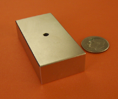
probably even a foot away.......the idea being to allow for use under a mantle or a bath of any sort without any problem. So I have some 1" square
solid cold rolled barstock
which will be precision square end cut to a length of 4 1/2 inches and have two mounting holes on 2 1/2 inch centers
to secure the block magnets through the armature bar and
the hub, allowing a 1/2 inch end gap between the block magnets. This assembly will fit onto any 1/2" drive motor shaft or a 1/2" arbor or spindle.
Two magnets may be stacked on each side, forming a sort of horseshoe or wide
U-shaped magnet assembly where the 1 inch solid piece
completes the backside magnetic circuit, and the field lines above the U-shape will arch across the space above like a rainbow, and couple solidly
with any magnetic stirbar in the
vicinity.
http://www.robotmarketplace.com/products/0-HUB21235.html

|
|
|
labfix
Harmless
Posts: 1
Registered: 18-10-2010
Member Is Offline
Mood: No Mood
|
|
I'm wondering why you didn't take the opportunity to buy a cheap and good working magnetic stirrer?
Check out the Topolino stirrer here
It's cheap and I can't imagine you can build such a magnetic stirrer by your own.
|
|
|
kmno4
International Hazard
Posts: 1495
Registered: 1-6-2005
Location: Silly, stupid country
Member Is Offline
Mood: No Mood
|
|
Quote: Originally posted by labfix  | I'm wondering why you didn't take the opportunity to buy a cheap and good working magnetic stirrer?
Check out the Topolino stirrer.
It's cheap and I can't imagine you can build such a magnetic stirrer by your own. |
0. It is not cheap.
1. Amateur construction similar to Topolino cost 10-20 euros max.
2. This is DIY not BIY ( B= buy) thread.
3. Some of us really can imagine such things like building similar (not such a) stirrers.
|
|
|
neelin
Harmless
Posts: 4
Registered: 25-10-2010
Location: Great White North
Member Is Offline
Mood: No Mood
|
|
| Quote: Originally posted by kmno4 | A heart of motorless stirrer: electromagnets (two pairs)
It is my own (working) construction, copyied (with small diffrences) from stirrer made in a factory
BTW: Has anybody seen amateur motorless stirrer ? |
No, I've been looking. Do you have a drive electronics schematic?
In the two years since this has been posted have you thought of any commodity consumer devices to scavange readymade electromagnets? Great project!
Robert
|
|
|
kmno4
International Hazard
Posts: 1495
Registered: 1-6-2005
Location: Silly, stupid country
Member Is Offline
Mood: No Mood
|
|
At last I have found time to draw it.
Sorry for "paintful" picture but I really tried....
As everybody can see, cost of electronic parts (even incuding generator) is about few euros.
Attachment: ecmst.pdf (16kB)
This file has been downloaded 1265 times
|
|
|
neelin
Harmless
Posts: 4
Registered: 25-10-2010
Location: Great White North
Member Is Offline
Mood: No Mood
|
|
| Quote: Originally posted by kmno4 |
At last I have found time to draw it.
Sorry for "paintful" picture but I really tried....
As everybody can see, cost of electronic parts (even incuding generator) is about few euros. |
Many thanks!!!
I'm new to digital electronics (but not linear), so I made a working model in LogicSim (the download Java, not the html applet) It's really cool, the light chases around in a circle representing one pole of the magnet!
Small things amuse small minds
[Edited on 2010.11.16 by neelin]
[Edited on 2010.11.16 by neelin]
[Edited on 2010.11.16 by neelin]
Attachment: Magnetic Mixer.lsim (10kB)
This file has been downloaded 1194 times
Robert
|
|
|
kmno4
International Hazard
Posts: 1495
Registered: 1-6-2005
Location: Silly, stupid country
Member Is Offline
Mood: No Mood
|
|
This circuit is rather simple: 2 X D latch and 4 NAND gates working in transmission mode and 4 ones working as negators.
I replaced CMOS-es by TTL-s: HCF4013 -> 7474, TC4011 -> 7400, remaining 4 gates were replaced by 4 transistors BC.... series. Transils were
replaced by 8 diodes between C and E. It is rather version, not improvement (8 elements instead of 2 ones).
How electromagnets can be constructed - see patent US2005088912A1 (very similar to my construction). Another examples with different shapes (and with
slightly different driving) can be found in patent CH612855A5.
|
|
|
neelin
Harmless
Posts: 4
Registered: 25-10-2010
Location: Great White North
Member Is Offline
Mood: No Mood
|
|
FWIW I had trouble finding that first patent, but I think this is the one that looks like your assembly: US#4,568,195 Feb. 4, 1986 "Magnet stirring
apparatus" Helmut Herz & Klaus Kaufmann of Germany. The multi-gang stirrers shown in the patent look surprisingly like currently available
multi/ganged induction style stirrers. Thanks for the info.
What combo of R1/R2 & C did you use on your 555 timer that worked good (i.e. what potentiometer ranged you through the 3-68hz you recommend). I
have two old UPS's that I think all parts can be scavenged except for the 555 that I already have.
I'm picking up some surplus "wall wart" power supplies tonight. I'll try peeling off the secondary windings bobbins and use them as-is with a new iron
core with the extension to make the top surface.
Robert
|
|
|
arsphenamine
Hazard to Others
Posts: 236
Registered: 12-8-2010
Location: I smell horses, Maryland, USA
Member Is Offline
Mood: No Mood
|
|
| Quote: Originally posted by neelin | | FWIW I had trouble finding that first patent, but I think this is the one that looks like your assembly: US#4,568,195 Feb. 4, 1986 "Magnet stirring
apparatus" Helmut Herz & Klaus Kaufmann of Germany. |
Check out figures 4 and 5 which show a steel?
connection between and below diametrically opposed cores. This delivers more magnetic field at the top.
|
|
|
neelin
Harmless
Posts: 4
Registered: 25-10-2010
Location: Great White North
Member Is Offline
Mood: No Mood
|
|
| Quote: Originally posted by arsphenamine | | Check out figures 4 and 5 which show a steel? connection between and below diametrically opposed cores. This delivers more magnetic field at the top.
|
I think KMNO4 was doing this already like this. The wiring diagram shows only 2 electromagnets, but they would actually be 4 coils wired to give
suitable N/S orientations.
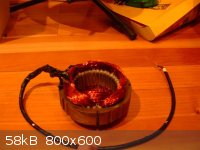
In the mean time, here's transformer off a UPS. This is not the main UPS transformer, it is the transformer that provides the charging power to the
UPS battery (12v7ah). I am surprised at how useless this is. At 9vdc 0.5a to the coil. The bottom of the photo show the original transformer, and
the upper part of the photo shows one disassembled & only the secondary coil used, dropped onto a cast iron base for a parts holder.
What am I doing wrong to generate such a feeble magnetism? If you look at a commerical Topolino mini stirrer the whole power consumption is only
5watts so they're not using a lot of power to the magnets. I though this was going to be the coolest with plenty of oomph from professionally wound
readily available coils.

Robert
|
|
|
kmno4
International Hazard
Posts: 1495
Registered: 1-6-2005
Location: Silly, stupid country
Member Is Offline
Mood: No Mood
|
|
As I wrote earlier - electromagnets are the most important part of such a stirrer
Without proper understanding it is not easy to construct such electromagnets.
Electromagnets in my model consume ~4 W (~0,3 A x ~12 V).
Driving transistors (BD135/136) work without radiators and they are barely warm.
I attach scheme of "555"generator (original version).
It is a little more complex, because of "soft start" function.
BTW.
Knowing patent number you can visit this site and copy/paste it there.
http://ep.espacenet.com/numberSearch?locale=en_EP
Attachment: gen.pdf (9kB)
This file has been downloaded 1081 times
|
|
|
obsessed_chemist
Hazard to Self
Posts: 65
Registered: 23-3-2007
Member Is Offline
Mood: electronegative
|
|
Improvement in DIY Electromagnet Stirrer
| Quote: Originally posted by kmno4 | ...electromagnets are the most important part of such a stirrer
Without proper understanding it is not easy to construct such electromagnets... |
|
|
|
obsessed_chemist
Hazard to Self
Posts: 65
Registered: 23-3-2007
Member Is Offline
Mood: electronegative
|
|
Improvement in DIY Electromagnet Stirrer
| Quote: Originally posted by kmno4 | ...electromagnets are the most important part of such a stirrer
Without proper understanding it is not easy to construct such electromagnets... |
Hi all, just thought I'd chime in. I have an idea for building an electromagnet-based stirrer. Instead of using a split-capacitor theme or fancy
electronics, why not just utilize a three phase stator with a motor driver from a small device. A brushless motor ESC used for motorized R/C vehicles
comes to mind. A motor requires at least three poles - at least to gain rotation - three being the key number here. Using only three poles makes this
simpler.

Anyway, on to my stator idea. In the realm of magnetic stirrers, in order to induce a rotating magnetic field vertically using electromagnets, we
ideally need what's known as an "axial flux motor" setup.

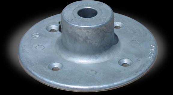
My idea: Take a steel pipe cap like the one seen above (schedule 40 or 80, perhaps, and of varying diameter based on intended use). First, grind off
the nubs on either side with a dremel. These are meant for assisting a plumber when screwing the cap on with a pipe wrench. This should leave a round
smooth surface above the rim of the pipe cap.
Next, drill a hole in the center, and then make three centered cuts, shifting the saw 60 degrees after each subsequent cut, sawing across the top
(sawing perpendicullar to the direction the hole was drilled) and continuing down either side, but stopping just at the top of the rim of the pipe
cap. This should now leave six 60 degree equal sections, like a pizza pie, but still connected at the rim, or widest part of the pipe cap.
Now, make three more cuts horizontally, and parallel to and just above the pipe cap's rim/lip, connecting the bottom of the previous cuts, removing
every other section. This should leave three sections uncut, equally spaced, or 120 degrees apart , and nearly coming to a point at the hole drilled
in the center of the cap. Looking at the top of the pipe cap should now resemble one of those old school radioactive, or bomb shelter warning signs.

With this done, the remaining vertical portions of each of the three "poles" of the pipe cap could now be wound each with a coil of thick magnet wire,
and wired into either a "Wye" or "Delta" configuration. The top portions of each section, between the the bend at the top and where they almost meet
in the center would be left unwound. Now by using a motor driver and some resistors to limit the current at each "leg" of the motor stator, one should
be left, in theory, with a cheap induction stirring device that can be submerged in water or oil baths without too much trouble.
A metal bandsaw or just an ordinary hacksaw should be able to do the job with some care taken to keep the cuts straight down the sides of the cap,
supporting it in a bench vise. A dremel tool with small cutoff wheel might be necessary to make the 3 horizontal cuts along the rim of the cap.
Obviously, rasping the cut edges smooth before winding the poles with wire would be in order.
It's hard to explain in words exactly what I mean, and I'm not good at paint shop. The "radioactive" hazard sign is the closest thing I can think of
to explain what the top of the pipe cap should look like.
I guess another way to describe what the pipe cap stator I envision from a three dimensional standpoint: Imagine a king's crenellated crown, the head
band being the base of the cap/stator, and the stalagmite-like or house-shaped crenellations, equally spaced at 120 degrees, and bending towards the
center of the crown midway. These are the poles of the stator.

The thick circular base of the cap should make a good base for the stator, balancing out the fields induced. Also, the triangular portion of the poles
coming almost to a point at the top should work well in directing the field in a geometrically appropriate, and efficient manner.
[Edited on 11/20/2010 by obsessed_chemist]
|
|
|
Stasis
Harmless
Posts: 7
Registered: 6-10-2010
Member Is Offline
Mood: Emulsified
|
|
Hey guys, just thought I'd comment based on my experiences with homemade stirrers. I've made a stirrer out of an eight-pole stator from an old washing
machine, and hooked it straight up to 240V mains voltage. The stirring torque it puts out is huge, but it has serious limitations:
1. The internal diameter of the iron core is only 8cm, my 250mL flask JUST fits inside.
2. The total resistance of the coil is 50Ω, so it puts out about 1150W of heat when connected to the mains. I need to hook it up to a light
dimmer or something, but I don't know if it would handle the power very well, and the nature of the dimmer may interfere with the rotating field.
I can post pictures if anyone's interested.
|
|
|
Stasis
Harmless
Posts: 7
Registered: 6-10-2010
Member Is Offline
Mood: Emulsified
|
|
I just tried to control the stirrer with a 400W dimmer, burnt it out within seconds... here's a picture of the coil, not in action as my 250ml flask
shattered..
|
|
|
obsessed_chemist
Hazard to Self
Posts: 65
Registered: 23-3-2007
Member Is Offline
Mood: electronegative
|
|
Hey Stasis, I was going to comment earlier, but maybe it's better that you burnt out the motor windings... 240V is just an excessive voltage to have
to utilize directly on the stirrer windings.
I imagined the motor stator that you had described as being a single phase induction motor with run-capacitor windings, since you mentioned there
being 8 poles, and it being from a washing machine. The stator shown in the picture you posted looks more like that of a universal series motor to me,
but I'm no expert. Although these type motors can be controlled with a dimmer, they're pretty much useless in our application, for technical reason I
won't delve into.
If you do decide to experiement again with a salvaged stator, try one from an old alternator, and use a motor drive to control the speed, as I had
mentioned in one of my replies above, several months back. At least this will help you avoid an electrocution hazard, since alternators typically
utilize lower voltages.
Also, if you do use a stator from a mains voltage motor again, try to power it through an isolation transformer, and go ahead and use
one that can step the voltage down to a safe range, or between 0 - 48V (Variac + Isolation Transformer would work well). Some electrical codes are
significantly relaxed or non-applicable at this voltage range since it is a lot less of an electrocution hazard. With a tiny magnetic stir bar, you
don't really need that much juice anyway. This will reduce current consumption and thus heat loss. Also, the voltage will basically have no effect on
the stirring speed. Instead, the speed of an asynchronous induction motor is based on the line voltage frequency, or the formula 120F/P -slip
(P=poles).
As soon as I have some time and the space to do so, I plan on making a prototype of the "pipe cap" stator I mentioned before. Give that a try if you'd
like. Other than the motor ESC, the rest of the materials might be lying around your garage.
[Edited on 12/4/2010 by obsessed_chemist]
|
|
|
Stasis
Harmless
Posts: 7
Registered: 6-10-2010
Member Is Offline
Mood: Emulsified
|
|
The motor itself is fine, it was the dimmer which burnt out. I knew it was going to happen, it was only rated to control 400W, and it got to around
70degC within about 20 seconds of operation.
| Quote: Originally posted by obsessed_chemist |
I imagined the motor stator that you had described as being a single phase induction motor with run-capacitor windings, since you mentioned there
being 8 poles, and it being from a washing machine. |
I'm pretty sure this is a single-phase induction motor, not quite sure what you mean by run-capacitor windings though. The stator originally had three
wires for electrical connection (red, white and blue) but I just connected the mains to red and blue and insulated off the white wire (which also had
a thermal protector in series)
I'm definitely no expert either, but from what I researched about these universal motors, it appears that the rotor has a coil structure as well as
the stator. The rotor from this motor was just the traditional squirrel cage. Again, I probably have no idea what I'm talking about...
Go on, I'm interested.
| Quote: Originally posted by obsessed_chemist |
use a motor drive to control the speed, as I had mentioned in one of my replies above, several months back. At least this will help you avoid an
electrocution hazard, since alternators typically utilize lower voltages. |
Thanks for the safety concerns, but there really is no electrocution hazard, everything is grounded to the hilt (which you probably can't see from the
photo).
| Quote: Originally posted by obsessed_chemist | | use [a transformer] that can step the voltage down to a safe range, or between 0 - 48V (Variac + Isolation Transformer would work well). With a tiny
magnetic stir bar, you don't really need that much juice anyway. This will reduce current consumption and thus heat loss. Also, the voltage will
basically have no effect on the stirring speed. Instead, the speed of an asynchronous induction motor is based on the line voltage frequency, or the
formula 120F/P -slip (P=poles). |
Thanks. I tried stepping it down to 22V with a transformer previously, the stirring was pathetic, even with my smallest stirbar. It works out to
around 9.5W of power I think, which was really useless. At 48V, it would be aorund 46W, which may or may not be sufficient. A variac would be great,
except they are horrendously expensive, and I might as well buy a hotplate/stirrer if I'm going to lay down >$250..
(Also, what is the point of having an isolation transformer in addition to the variac? Would the variac not perform this function itself??)
|
|
|
Gearhead_Shem_Tov
Hazard to Others
Posts: 167
Registered: 22-8-2008
Location: Adelaide, South Australia
Member Is Offline
Mood: No Mood
|
|
| Quote: Originally posted by Stasis |
...
(Also, what is the point of having an isolation transformer in addition to the variac? Would the variac not perform this function itself??)
|
Variacs are usually autotransformers; they don't have two windings, primary and secondary, rather they have one winding used sorta like a
potentiometer voltage divider. This means they don't provide galvanic isolation between input and output. As long as what you think are Hot
and Neutral on your AC input lines really are, then you're OK. If they are reversed, though, you could have the lethal situation of having
Hot connected to what should nominally be at AC ground potential. Since this is often connected to a metal chassis, the first time you touch both the
chassis and a true ground will unfortunately also be your last time.
-Bobby
|
|
|
| Pages:
1
2
3
4
5 |


