| Pages:
1
..
3
4
5 |
puppycock
Harmless

Posts: 11
Registered: 1-4-2010
Member Is Offline
Mood: No Mood
|
|
Low budget stirrer
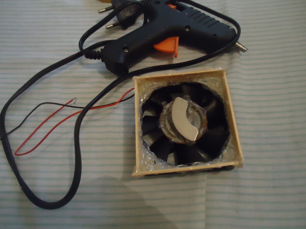
I just finished my homemade stirrer, I used:
1. DC motor from old inkjet printer
2. Magnet from broken 3.5" Hard Drive
3. Spare AC to DC 5V/2A adapter from a PSP
4. Wood and Plastic Sheet for the casing
It was pretty easy once I figured out how to adapt the magnet to the motor, first I used some rubber bands connected to a ball bearing where the
magnet was going to fit but finally I just simply glued the magnet to the motor and it fitted quite nice and is also balanced.
The motor and magnets were free, the adapter and casing costed about $5 combined.
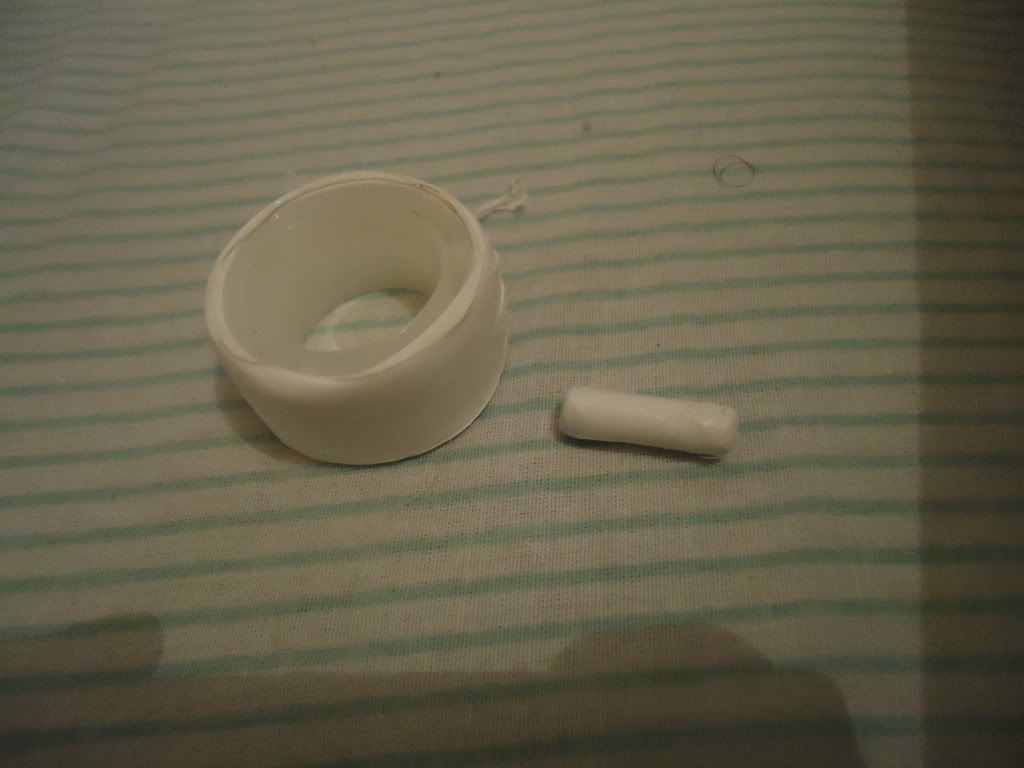
First picture shows all parts (red layer is water with colorant and clear layer is mineral oil).
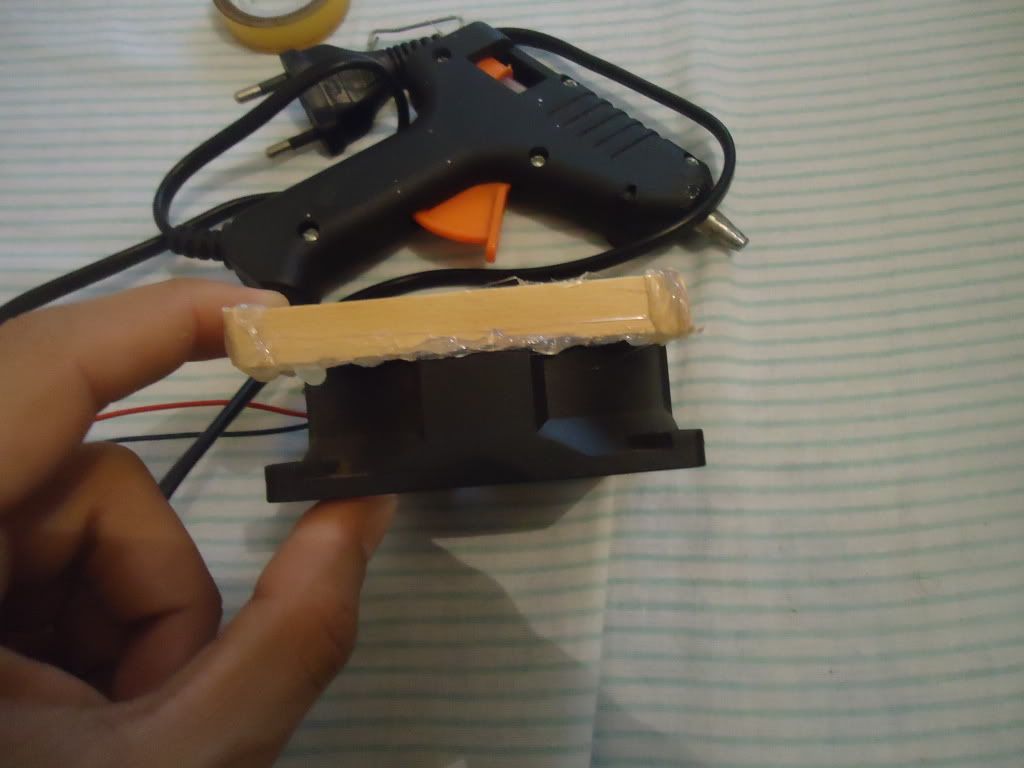
Second picture is a macro of the motor attached to the base.
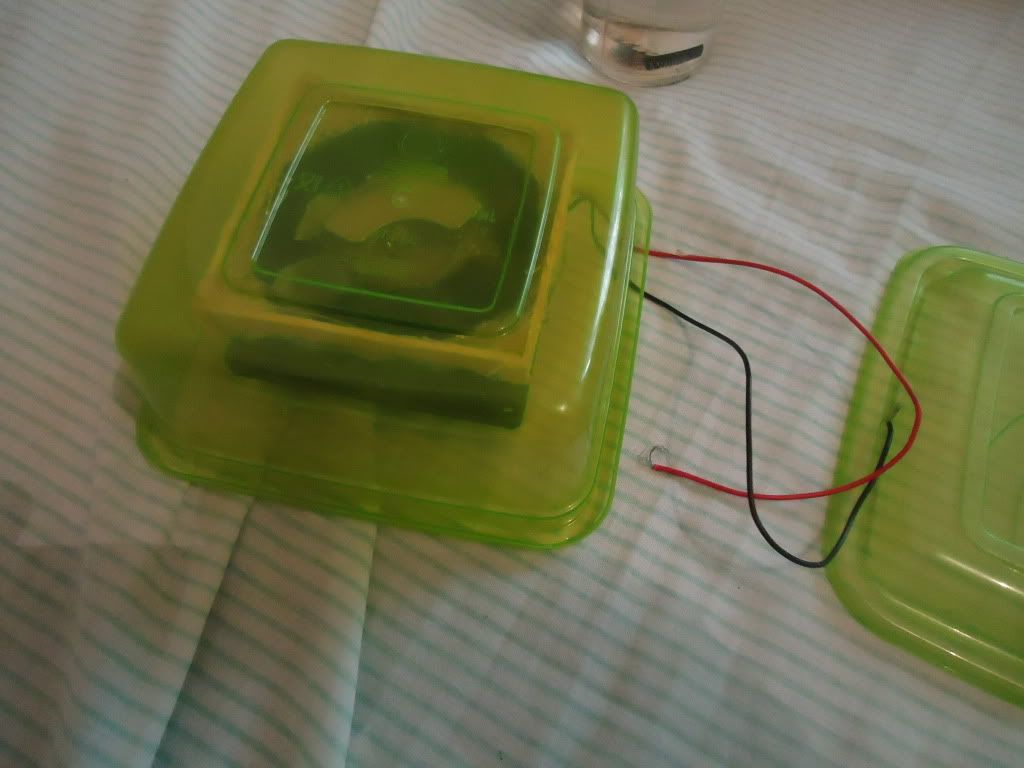
Third picture shows the stirrer working (you can no longer see the two layers).
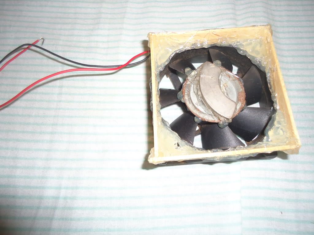
Fourth Picture is a macro to the "whirlwind" (I don't know the proper word in english) which is barely visible btw.


[Edited on 6-12-2010 by puppycock]
|
|
|
watson.fawkes
International Hazard
Posts: 2793
Registered: 16-8-2008
Member Is Offline
Mood: No Mood
|
|
Quote: Originally posted by puppycock  |
Fourth Picture is a macro to the "whirlwind" (I don't know the proper word in english) which is barely visible btw. |
"Vortex".
|
|
|
Stasis
Harmless
Posts: 7
Registered: 6-10-2010
Member Is Offline
Mood: Emulsified
|
|
| Quote: Originally posted by Gearhead_Shem_Tov |
Variacs are usually autotransformers; they don't have two windings, primary and secondary, rather they have one winding used sorta like a
potentiometer voltage divider. This means they don't provide galvanic isolation between input and output. As long as what you think are Hot
and Neutral on your AC input lines really are, then you're OK. If they are reversed, though, you could have the lethal situation of having
Hot connected to what should nominally be at AC ground potential. Since this is often connected to a metal chassis, the first time you touch both the
chassis and a true ground will unfortunately also be your last time.
-Bobby |
Ah ok, thanks for the info. Live and Neutral are always the same sides, but in saying that, it's hardly something I'd be willing to mess around with..
|
|
|
iHME
Harmless
Posts: 30
Registered: 29-10-2008
Location: the arctic circle
Member Is Offline
Mood: No Mood
|
|

My magstirrer.
LM317 as a speed controller and a hdd magnet glued on a 92mm casefan.
Simple cheap and good enough.
Here's a gallery with more indepth and build pix.
http://img72.imageshack.us/gal.php?g=img8351c.jpg
It\'s a catastrophic success.
|
|
|
Gearhead_Shem_Tov
Hazard to Others
Posts: 167
Registered: 22-8-2008
Location: Adelaide, South Australia
Member Is Offline
Mood: No Mood
|
|
| Quote: Originally posted by Stasis | | Quote: Originally posted by Gearhead_Shem_Tov |
... As long as what you think are Hot and Neutral on your AC input lines really are, then you're OK. If they are reversed,
though, you could have the lethal situation of having Hot connected to what should nominally be at AC ground potential. Since this is often connected
to a metal chassis, the first time you touch both the chassis and a true ground will unfortunately also be your last time.
-Bobby |
Ah ok, thanks for the info. Live and Neutral are always the same sides, but in saying that, it's hardly something I'd be willing to mess around with..
|
Hot and Neutral are always supposed to be wired to specific terminals, but I've come across plenty of outlets/power points where this is not
true. A house may be wired by an electrician, but that doesn't stop non-electricians from subsequently replacing fixtures or making modifications,
and each time this happens there's a chance for swapped wires.
Don't let your life depend on the assumption that this has not happened.
-B
|
|
|
dean stark
Harmless
Posts: 12
Registered: 17-3-2011
Member Is Offline
Mood: No Mood
|
|
Stator and back-EMF
A nod to Stasis, obsessed_chemist, and kmno4.
The Stator idea is f**king cool.
2mag stirrers are made along these lines. They use something called "SoftStart" which enables "catching/centering and safe acceleration of the
stirring bar".
I don't know too much about motor electronics, but is this something to do with back-EMF?
In the article "Back-EMF Motion Feedback" the author describes a process where a motor is momentarily allowed to spin freely in order to take a voltage reading in
order to correct the motor speed.
Even if EMF is induced it might be difficult to do this due to multi-phase power...
Any thoughts?
|
|
|
Aqua_Fortis_100%
Hazard to Others
Posts: 302
Registered: 24-12-2006
Location: Brazil
Member Is Offline
Mood: †
|
|
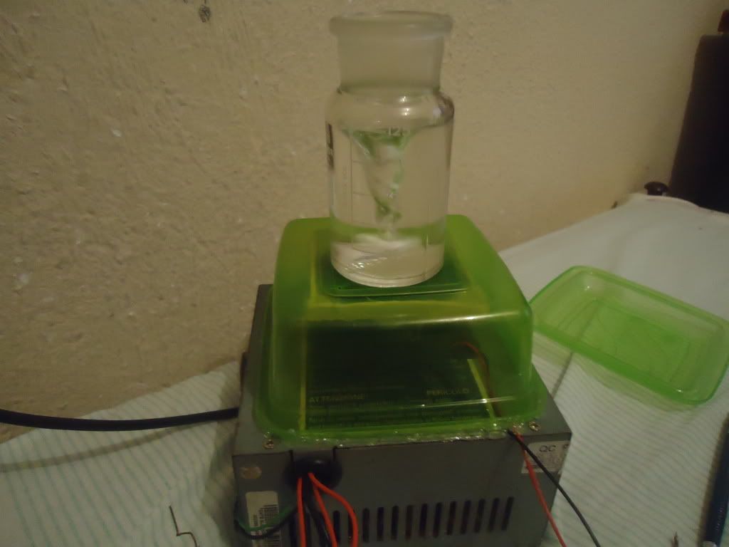
I made a while ago (all the process wasted only about 1 hour) a improvised magnetic stirrer to make some experiments with mead (fermented honey)..
Two same HD magnets were glued on a mild steel disk and this on a ordinary 12V PC cooler:
Some small wood pieces were glued in the way seen in picture to form a little gap between rotating magnet and upper surface in which the container
with stirr bar will rest.
The steel disk was necessary to shield the cooler against the magnetic field of the magnets. Without it the cooler just dont spin.
Detail:
A cheap plastic bowl was used as this 'upper surface':

glued:
and this was glued above an old ATX PC power supply (with most of it wires removed). I forgot to took photos of that step, but doesnt matter as it
will be evident below.
Next, the stirr bar.
Looking my box with an assortment of electronic components (most of it scavenged from scrap), I found an interesting small inductor:
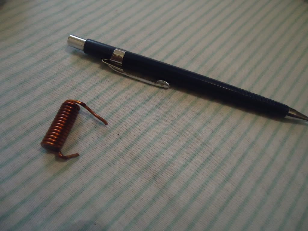
removed the copper wire:
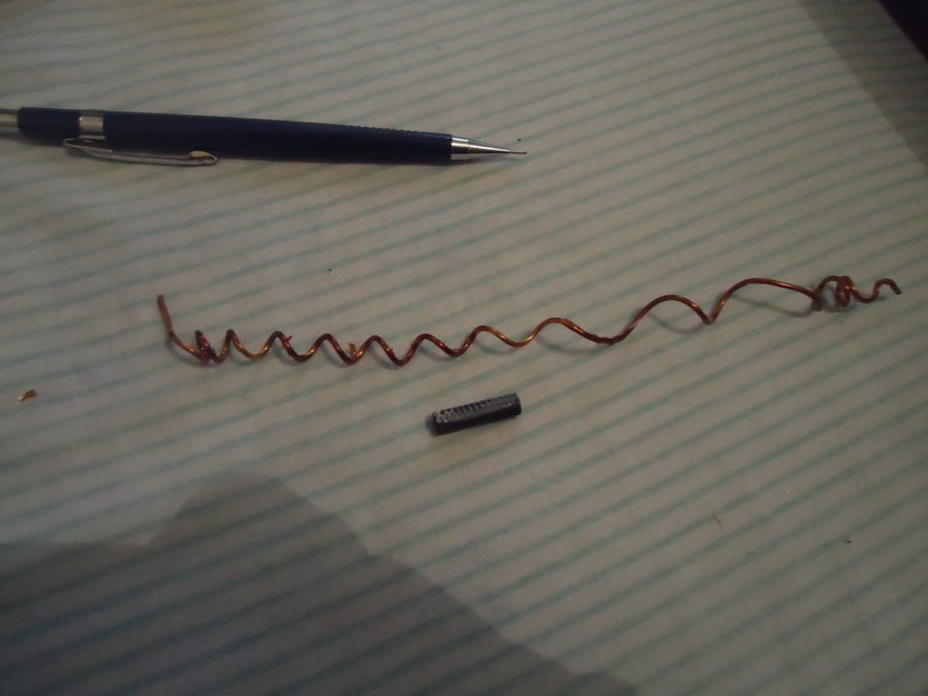
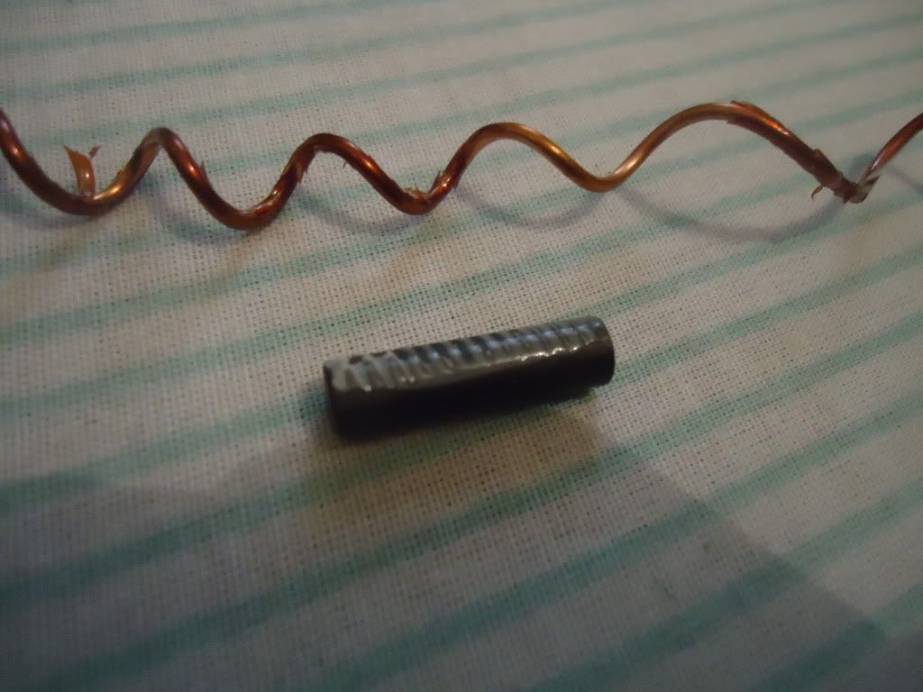
Then sanded the soft ferrite rod and washed it in hot acetone (to remove glue traces), then water, then dried it.
Next step was tight winding PTFE tape on it.
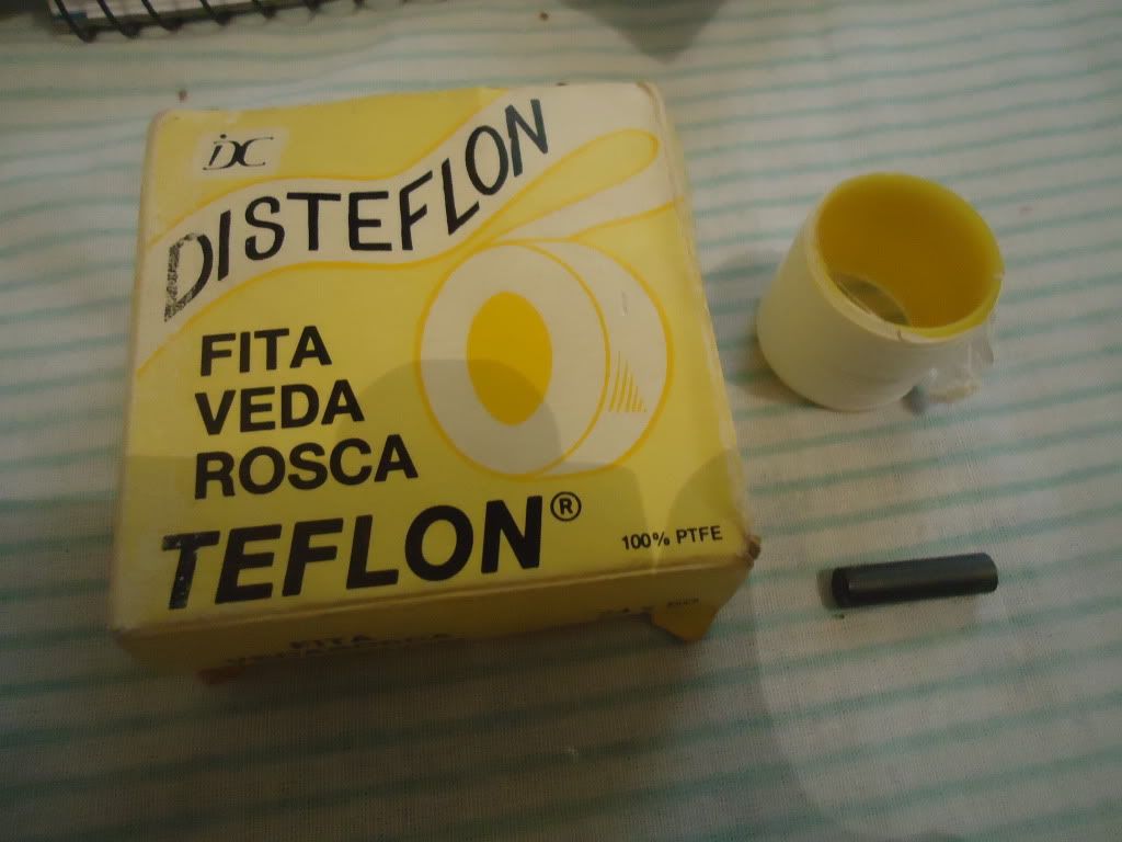
The result:
The whole thing at work:
Video I made from operation:
<iframe sandbox width="420" height="315" src="http://www.youtube.com/embed/noIIbJhec_E" frameborder="0" allowfullscreen></iframe>
[Edited on 17-10-2011 by Aqua_Fortis_100%]
"The secret of freedom lies in educating people, whereas the secret of tyranny is in keeping them ignorant."
|
|
|
Nicodem
Super Moderator
Posts: 4230
Registered: 28-12-2004
Member Is Offline
Mood: No Mood
|
|
Nice, but just a comment: It is not at all safety-wise to put the power supply under the stirrer. That is quite insane actually. Spillovers are pretty
common from mixtures stirred above a stirrer. That's why the commercial stirrers are always build in such a way that spillovers can not make it to any
electric component.
Besides, choosing a PC cooling fan as the electromotor and the PC power source is far from optimal. If you take a normal electromotor you can regulate
the RPM value by a simple one transistor current regulator that takes just a few minutes of work (did this and used the home-built stirrer for years).
An old cellular phone charger (0.5-1 A) is generally enough as a power supply for such a low power stirrer (provided you use a small ~3-5 W
electromotor for about 5 V - surprisingly they are enough for most uses on scales up to a 250 mL flask!). As an advantage, such a power source is
already suitably built, small and it keeps the network tension away from your bench. For stronger stirrers (electromotors), you can cheaply buy
stronger adaptors and if you use a cheap generic 0-12 V lab power supply you already have the RPM regulation built in by regulating tension (last time
I checked they cost no more than 25-50 EUR). Note that RPM regulation by voltage control will not work on stepping or servo motors or any other
electronically driven ones (like PC fan).
…there is a human touch of the cultist “believer” in every theorist that he must struggle against as being
unworthy of the scientist. Some of the greatest men of science have publicly repudiated a theory which earlier they hotly defended. In this lies their
scientific temper, not in the scientific defense of the theory. - Weston La Barre (Ghost Dance, 1972)
Read the The ScienceMadness Guidelines!
|
|
|
Aqua_Fortis_100%
Hazard to Others
Posts: 302
Registered: 24-12-2006
Location: Brazil
Member Is Offline
Mood: †
|
|
Thanks Nicodem, actually this is so obvious that I didnt noticed. =)
Anyway, this is not to be a problem tought, since like I said, I will use it to make mead (to stirr yeast in a closed system and make something better
suited to get me and my several girlfriends drunk  ). ).
My plan to make a stirrer ideal to chemistry hobby includes a heating unit too, like 'professional' units. So the tip you gave about motor will be
useful and I will use that in future, thanks!
"The secret of freedom lies in educating people, whereas the secret of tyranny is in keeping them ignorant."
|
|
|
gatosgr
Hazard to Others
Posts: 237
Registered: 7-4-2015
Member Is Offline
Mood: No Mood
|
|
Why not use the circuit of a bldc motor and just rewind the coils or use a ferrite material shaped to redirect the magnetic flux at the top where the
stir bar would be?
[Edited on 6-6-2016 by gatosgr]
|
|
|
battoussai114
Hazard to Others
Posts: 235
Registered: 18-2-2015
Member Is Offline
Mood: Not bad.... Not bad.
|
|
| Quote: Originally posted by gatosgr | Why not use the circuit of a bldc motor and just rewind the coils or use a ferrite material shaped to redirect the magnetic flux at the top where the
stir bar would be?
[Edited on 6-6-2016 by gatosgr] |
Seems this guy did it, though my Russian skills are non-existent
https://www.youtube.com/watch?v=sED4zU68AwQ
Batoussai.
|
|
|
| Pages:
1
..
3
4
5 |


