| Pages:
1
2
3
..
5 |
woelen
Super Administrator

Posts: 7976
Registered: 20-8-2005
Location: Netherlands
Member Is Offline
Mood: interested
|
|
Dangers/risks of Mazilli ZVS driver?
I ordered the components for making a Mazzilli driver. It looks very simple:
https://sites.google.com/site/uzzors2k/mazzilli_zvs.png
It must not be too difficult to wire up such a beast. I never heard of this fairly recent discovery and was amazed to see that this can be built for
just EUR 15 with easy to find components (local shops, or eBay).
Is there anyone here who has first hand experience with this driver? I read reports of impressive results (e.g. transferring hundreds of Watts of
power to a transformer, or even to a piece of metal without any physical contact with the metal), but I also read reports of explosions of components
and very dangerous energetic bursts, destroying the driver plus the power supply and possibly other things as well. I do not want disaster in my lab
when I power on the device.
I want to use the driver to heat mixes of e.g. SiO2 with Mg and MgO, red P with metals and oxide or sand as a heat moderator or any other fine mixes
of metals and non-metals which are hard to ignite. I have seen pictures of coils, made from 4 mm thick copper wire, having ten or so turns and having
an inner diameter of 2.5 cm or so. With this they could heat blocks of metal to a red heat.
I also have seen people make ultra hot and long plasma arcs with just a simple transformer, having 10 turns on the primary side with very thick copper
wire and having a few thousands of turns on the secondary side. Experimenting with that also looks interesting.
I have a few questions:
- How does the driver behave when there is no load? Does it just draw a small current from the power supply in that case?
- If I connect a transformer to it (e.g. 5 + 5 windings primary, 2500 windings secondary) and have no load attached to that secondary, how does the
driver behave in that case?
Actually, I really would like to limit the current capabilities of the driver in my first experiments. If I limit the current with a big power
resistor of e.g. 3.3 Ohm in series with the 12 V power supply, does it still work, abeit with lower energy?
[Edited on 30-6-14 by woelen]
|
|
|
Metacelsus
International Hazard
Posts: 2531
Registered: 26-12-2012
Location: Boston, MA
Member Is Offline
Mood: Double, double, toil and trouble
|
|
I've tried to make one. It's a lot harder than it seems (or maybe my IRFP460 MOSFETs were just bad quality) because it kept overheating (even though
it's designed not to), and my MOSFETs eventually died. I eventually changed to a 555 timer flyback driver, which for me is less powerful but more
reliable.
In my experience, the driver essentially draws the same current whether there is a load or not. I'm not sure what effect limiting the current would
have--it might not even work at all.
|
|
|
WGTR
National Hazard
Posts: 971
Registered: 29-9-2013
Location: Online
Member Is Offline
Mood: Outline
|
|
I'm posting from my phone, so this will be quick for now. Electronics is my job. I would strongly recommend starting out small, with low power, and
then scaling up. You have to verify with a scope that there aren't any high voltage spikes where there shouldn't be. Those are things that may
cause power electronics to work at low voltage, and then fail when full voltage/power is applied. Also, it's generally better to separate the power
drivers from the oscillator function. This is better design practice.
I can offer some better tips later.
|
|
|
papaya
National Hazard
Posts: 615
Registered: 4-4-2013
Member Is Offline
Mood: reactive
|
|
Long time ago I tried it and it worked (had no secondary wire and core - just 2 primaries side by side and when you put an iron nail inside it gets
red hot.. however this is only with ferromagnetic metals )! What I've learned it is really powerful, but transistors MUST be heatsinked as well as the
choice of the components is really the key. Other things - the frequency is not constant and depends on load, also it will not give you sine waves as
you might already know..
|
|
|
SM2
Hazard to Others
Posts: 359
Registered: 8-5-2012
Location: the Irish Springs
Member Is Offline
Mood: Affect
|
|
Encase in epoxy sarcophagus once verified working (non conductive electrically, of course.)
This is how our military hardens the circuit boards in thermonuclear weapons, ensuring ruggedness and heat sink. Just an I-Dear.
"Old men who speak of victory
shed light upon their stolen life
they - drive by night- and act as if they're
moved by unheard music." B. Currie
|
|
|
bob800
Hazard to Others
Posts: 240
Registered: 28-7-2010
Member Is Offline
Mood: No Mood
|
|
From your post I'm not certain as to what you're planning on powering... is it a flyback transformer or an induction heating coil? I have built
essentially the same circuit and used it for an induction heater, with moderate success. I was able to heat nails to redness in around 10-15 seconds,
and slightly larger metal pieces to orange heat with longer heating.
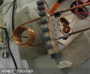
The actual ZVS driver is mounted to the right of the capacitor array. I soldered a copper tab onto each pipe, drilled a hole and then mounted each
MOSFET on the tabs. This way the water coolant served to keep both the MOSFET and workcoil cool without large heatsinks.
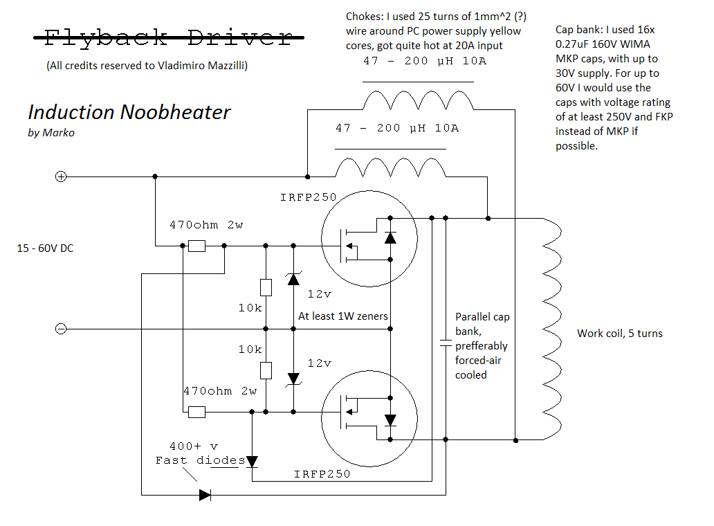
I used a slightly different circuit configuration (see schematic), with 2 inductors instead of 1 to avoid center-tapping the work coil. I would recommend this configuration.
I can post more info on the capacitors and # of turns, etc, if you are interested. Do you have a high-current capacity power supply? I used a rewound
microwave oven transformer. To take advantage of the full potential of this design you will need around 20A current.
I did not have problems with things exploding like you mentioned, However, with larger workpieces the setup sometimes began to drift off resonance,
causing a huge surge in current and loud buzzing noise. In these instances I could usually save the circuit by unplugging it immediately. For this
reason I would not recommend the circuit for higher power applications... I could never draw more than ~10A without running off resonance, but that's
probably due to the way my LC tank turned out.
This is a fun project, but if you want more useful output I would go with a half bridge/full bridge configuration (http://uzzors2k.4hv.org/index.php?page=pllinductionheater1). Also, I will say the ZVS driver works for flybacks, but again I had the same problem
with drifting off resonance...
**Also per your question about current without load, it drew only about 0.5A without a workpiece. As progressively larger workpieces were introduced
into the coil, the current draw increased to a~10A. Parallel LC tanks will always work this way (my configuration), but if you use a series
configuration there will be a large current draw without load.
[Edited on 30-6-2014 by bob800]
|
|
|
WGTR
National Hazard
Posts: 971
Registered: 29-9-2013
Location: Online
Member Is Offline
Mood: Outline
|
|
I don't plan on posing this way normally, but I'm playing with my new surface pro.
If I have some time I'll throw this together and see if it works... or someone else "knowledgeable in the art" can try it.
|
|
|
IrC
International Hazard
Posts: 2710
Registered: 7-3-2005
Location: Eureka
Member Is Offline
Mood: Discovering
|
|
Very similar in theory to the chopper power supplies of old. They used PNP Ge round body stud mount devices push pull with 60 ampere Ic ratings to
develop the high voltage to run tube mobile RF power amplifiers from the 13.8 volt vehicle source. Nowhere as efficient as these newer Hexfet designs.
However I think you would do better by picking devices with design specs better suited to repetitive avalanche operation. As example the IRFP264. For
this type of circuit it is also good to have a lower reverse transfer capacitance and as low of an RDS as possible. As has been mentioned already the
'ringing' capacitor needs ESR and dissipation ratings well suited for high dV/dt and a decently high voltage rating. I would want a supply adjustable
from 8 to 50 volts capable of 30 or 40 amperes. Start low and work your way up. Unless your going for risky power levels I cannot see running much
above 50 volts.
Wouldn't hurt to have a shrapnel shield for the Mosfets and capacitor. Hard sharp pieces of plastic at a few hundred FPS would tend to be painful.
IRFP264 IXYS MOSFET 38 Amps 250V 0.075 Rds, Dynamic dV/dt Rating, Repetitive Avalanche Rated.
Attachment: IRFP264.pdf (168kB)
This file has been downloaded 776 times
As you can see VDSS, RDS, and ID are all better suited for your circuit than the IRFP250.
"Science is the belief in the ignorance of the experts" Richard Feynman
|
|
|
woelen
Super Administrator
Posts: 7976
Registered: 20-8-2005
Location: Netherlands
Member Is Offline
Mood: interested
|
|
Hmmm... I only have limited equipment for this kind of things. I have a fixed power supply, 13.8 V/12 A max. It is very sturdy and is made from a big
transformer and a few big transistors, so I am not afraid that I kill the power supply.
I also already purchased the IRFP250 devices. They were moderately expensive, appr. EUR 1.50 per piece. The IRFP264 is much more expensive, at least
EUR 3 per piece, plus shipping. If I can expect to blow out a few of them, then this project can become expensive, but I certainly will consider the
purchase of the IRFP264.
I also can obtain IRFP260 devices for less money. What is your opinion on those?
I also saw IRFP264 transistors from Chinese sellers, for less than 1 euro per piece and free shipping. It sounds too good to be true. Are these good
quality components?
|
|
|
bob800
Hazard to Others
Posts: 240
Registered: 28-7-2010
Member Is Offline
Mood: No Mood
|
|
I can't remember off the top of my head, but I recall a discussion where some subtler advantages of a IRFP450 over an IRFP460 were discussed, even
though the Rds is better with the IRFP460(perhaps it was decreased gate capacitance, body-diode turn-on time, etc). I would think the same concept
would apply to the IRFP250/260.
I have always used '50' variants without issues, though I haven't compared them against '60's. I doubt it matters a whole lot for <1MHz speeds.
|
|
|
Burner
Hazard to Others
Posts: 100
Registered: 28-3-2014
Member Is Offline
Mood: No Mood
|
|
You can even find the IRFP450s for about 1USD each in quantities of 20 (http://www.ebay.com/itm/20PCS-IRFP450-HARRIS-TRANSISTOR-TO-2...). That makes them quite attractive.
|
|
|
IrC
International Hazard
Posts: 2710
Registered: 7-3-2005
Location: Eureka
Member Is Offline
Mood: Discovering
|
|
Quote: Originally posted by woelen  | | I also saw IRFP264 transistors from Chinese sellers, for less than 1 euro per piece and free shipping. It sounds too good to be true. Are these good
quality components? |
I'll let you know. I ordered 10 of them yesterday to play with your circuit. Usually takes a couple weeks to arrive plus the time for me to get around
to building something. My main point was by picking devices with better parameters for this type of operation you make the circuit less likely to blow
Mosfets meaning over time cost is lower. Possibly performance improves as well.
Edit: also ordered ten IRFP260's just for the heck of it. As to your question woelen about quality: I have bought over ten grand in semiconductors
from various ebay sellers in China so far this year. Twice I received rejects (likely fakes), 2SC2075, 2SC1969. Out of a very large number of
electronic parts from A to Z. Both from same seller, now on my blocked list just in case I forget one day.
[Edited on 7-2-2014 by IrC]
"Science is the belief in the ignorance of the experts" Richard Feynman
|
|
|
IrC
International Hazard
Posts: 2710
Registered: 7-3-2005
Location: Eureka
Member Is Offline
Mood: Discovering
|
|
Another thought after studying the circuit is if one does not properly consider the switching speed of the two diodes there is a danger of the Mosfets
conducting destructively. I suggest you consider the MUR 460, a 600V, 4A ultra-fast diode. Just a thought anyway.
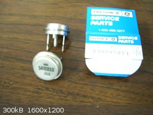
Found a couple pics of the old chopper transistors I mentioned in another post. One is PNP Ge and the other is NPN Si, included it because case style
is correct and it's hard to find images of these old devices. AFAIK only the PNP Ge types were used in the HV supplies for tube mobile gear. Also used
in the later 50's Delco-Remy car radios to get away from the old vibrator supplies. So if your junking an old Cadillac save the AM radio those chopper
transistors are becoming extinct.
"Science is the belief in the ignorance of the experts" Richard Feynman
|
|
|
12AX7
Post Harlot
Posts: 4803
Registered: 8-3-2005
Location: oscillating
Member Is Offline
Mood: informative
|
|
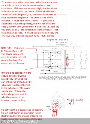
Going for voltage, this is one option:

The switching transistor can be salvaged from an old PC supply, usually a C2625 or something like that. +V can be the same +12V, or anything else.
(Actual CRT TVs and monitors use 100-160V, or probably 320V in 240VAC countries, and an internal winding; just put on your own winding, make sure of
course you find a flyback transformer that you can still get wire around the core.)
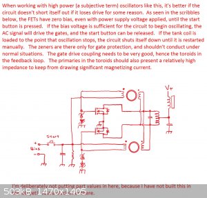
For dumb oscillator purposes, i prefer a variation something like this (you can ignore the top half of the circuit):

The 0.1 capacitor between transistor drains should be selected to resonate with the primary at the same frequency as the secondary.
Tim
|
|
|
jock88
National Hazard
Posts: 505
Registered: 13-12-2012
Member Is Offline
Mood: No Mood
|
|
You can purchase directly something along the same lines.
http://www.ebay.co.uk/itm/12V-24V-36V-Flyback-Driver-Board-Z...
|
|
|
IrC
International Hazard
Posts: 2710
Registered: 7-3-2005
Location: Eureka
Member Is Offline
Mood: Discovering
|
|
Woelen your question was about "Dangers/risks"
Being too impatient to wait for the parts on order, I decided to try the circuit using some 500 volt Mosfets which are rated at 4 amperes I had on
hand. I built the circuit to operate at lower current than the specs posted in this thread. Not only does the circuit work well, it imparts greater
energy density into the windings than other circuits I have tried over the years, when considering the power input. Meaning efficiency is far higher
than your 'typical' designs. In fact the design kicks ass fairly well, I like it. Waiting to get my orders and build a much higher current version.
Upon power up a virtual short circuit exists for both fets. As the current inrush builds magnetic field in the coil the back EMF shuts off the
opposite fet from each end of the coil. If it did not destruction is impossible to avoid. When the 'ringing' voltage is large the .68 uF capacitor
will destruct if it's dissipation is high, or voltage rating is low. If a short circuit occurs from insufficient back EMF to shut it off every cycle
(or if the fet shorts from over current or over voltage), the fet explodes. The greater the energy input the 'bigger the bang' obviously. So I see two
dangers. One is simple shrapnel from either a fet or the capacitor. Avoided very simply by a shield to keep a high velocity chunk from putting out an
eye.
The second danger is electrocution as the power level at high voltage (back EMF and/or transformer secondary) is quite high. That's it, nothing to
worry about if safe procedures are followed combined with common sense. A chunk of Mosfet at firearm velocities can be very dangerous yet minor
shielding is adequate since the mass of the plastic pieces is low.
If you look at inductive heating they typically use 8 turns center tapped of Cu tubing around 6" in diameter. Going by pictures in some of the ebay
auctions for factory built driver boards. For a circuit using a transformer primary they use 10 turns CT on a ferrite core. Being proven to work I
would call this the 'starting value' of the end design. So calculate the 'safe' inductance, using the values shown to work. If L is too low not enough
back EMF will develop to shut off the Mosfets guaranteeing destruction of the devices. If L is too large the excessive back EMF is going to explode
the capacitor or cause a destructive short in one or more Mosfets. It is as simple as this. Which also includes consideration of the voltage/current
input from your supply obviously. Start with proven values for the turns, and for current draw since this will cause either over current destruction
of the Mosfets or again excessive back EMF to develop. I imagine most having problems with parts exploding are either running too much power into the
circuit or not considering the load and the needed back EMF to turn off their Mosfets, i.e., using too few turns. Or as stated too high of a back EMF.
An oscilloscope would be useful to monitor the back EMF so one can calculate proper component ratings for safe operation. Another thing is looking at
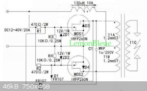
some of the factory made units I see on ebay, they are using 1 uF not the 0.68 uF indicated in this thread. I am sure a range of values will work
here, worth considering the frequency of operation since for example many TV flyback transformers operate with greatest efficiency in the 15 KHZ to 17
KHZ range. Playing around with the frequency of operation may be useful when considering what it is you plan on driving with this circuit. I am
interested in the use for inductive heating. Since I imagine Tim (12AX7) has more knowledge than other members about inductive heating circuits I
wonder what he might have to say about what the best frequency of operation is. Also what is the optimum inductance for the Cu tubing coil. I am sure
there is an optimum range for L/C ratio and wonder what his thoughts are about this.
"- How does the driver behave when there is no load? Does it just draw a small current from the power supply in that case?-
If I connect a transformer to it (e.g. 5 + 5 windings primary, 2500 windings secondary) and have no load attached to that secondary, how does the
driver behave in that case? Actually, I really would like to limit the current capabilities of the driver in my first experiments. If I limit the
current with a big power resistor of e.g. 3.3 Ohm in series with the 12 V power supply, does it still work, albeit with lower energy?"
If you study the circuit the Mosfets are biased fully on by design at power up. If no windings are connected to the Mosfets there is no drain current.
But if there is, the circuit is going to run at fairly high power depending upon power input, DC resistance and developed back EMF. It may merely be
generating a large magnetic field and high voltages from back EMF and loading will increase power draw, but I do not see how this circuit is going to
'loaf' at little power just because you have not loaded it. This design is not going to behave as a simple transformer which is not loaded on it's
secondary. You will no doubt see a range of power draw depending upon how much resistance you put in series with the input and how heavily you load
it. However I think you must consider the fact that if your developed back EMF is too low to fully shut off the Mosfets, basically you have two turned
on devices presenting a dead short to the power input over too much of the cycle or just plain 'on' meaning a dead short all the time. From this one
can conclude even at light loading it must still be running at a high enough power level to create the needed back EMF to turn off the devices and
maintain nonstop oscillation. I imagine you need to consider this in your design. Operating at low voltages is possible so long as you keep the
circuit in oscillation at all times when powered.
For clarity my last comments pertain to looking at both the circuit in the starting post, and the schematic I borrowed from the auction listed below.
http://www.ebay.com/itm/12V-24V-36V-Flyback-Driver-Board-Zer...
"Science is the belief in the ignorance of the experts" Richard Feynman
|
|
|
WGTR
National Hazard
Posts: 971
Registered: 29-9-2013
Location: Online
Member Is Offline
Mood: Outline
|
|
To both agree with IRC and clarify a few things from a different viewpoint, here goes.
For the purpose of argument for now, we can assume that full power supply voltage is applied to the circuit instantaneously(i.e., with an infinitely
fast rise-time). The RC filter network composed of the 470 ohm resistor + the MOS1/2 gate capacitance has a time constant, which causes a short
delay in the gate to source voltage (Vgs) rise. This time constant is significant only up to the gate threshold voltage (Vth), where MOS1/2 begins to
conduct. Up until this threshold is reached, drain to source current (Ids) is zero, and the voltage rise at the output of the 130uH inductor is
instantaneous. Once Vth is reached, the rate of rise in Vgs is limited by the rise in Vds (drain to source voltage), which is in turn limited by the
130uH inductor. Assuming a well-coupled transformer, T1 inductance is zero, since the flux is cancelled by both MOSFETs conducting simultaneously.
In a perfect world, with both halves of the circuit being perfectly matched and symmetrical, the MOSFETs will then go into thermonuclear meltdown.
Since we don't live in a perfect world (whew!), there is sufficient thermal noise, or there is some asymmetry somewhere that causes one half of the
circuit to conduct before the other. At this point, due to D1, and D2, and T1, there is positive feedback that drives the circuit into instability
(oscillation).
The 130uH inductor is needed, not so much for power supply filtering, but to limit the Vds rise-time on start-up. Without it full voltage will get
applied to both MOSFETs (which are already "ON"), with the MOSFETs acting as the primary current-limiting (and power dissipating) devices. An
improvement to this circuit would be to add a resistance from the output of the 130uH inductor to ground, to improve start-up performance. This
resistance would counteract the negative effects of the parasitic capacitance in the inductor, which can cause voltage to rise too quickly on the
MOSFETs on start-up. It's a minor improvement.
I do think that if the supply voltage is brought up very slowly, there will be a region of operation where the circuit will consume power without
oscillating. This would be related to the limited voltage swing at the gate at certain supply voltages.
[Edited on 7-8-2014 by WGTR]
|
|
|
IrC
International Hazard
Posts: 2710
Registered: 7-3-2005
Location: Eureka
Member Is Offline
Mood: Discovering
|
|
No doubt. Just playing around with my junk box parts makeshift version (to say non optimized in every parameter is an understatement), around 8 volts
is the lowest 'instant on' (applying power) voltage desirable, or not enough noise combined with correct conditions exists and oscillation will not
commence. Bad for the Mosfets. I have no doubt a lower voltage version would be useful in some applications with proper design. More inductance in the
supply choke for example. Wish my orders from China arrived more quickly I really want to recreate the exact circuit. Likely still a couple weeks away
at least.
"Science is the belief in the ignorance of the experts" Richard Feynman
|
|
|
quantime
Harmless
Posts: 18
Registered: 26-6-2014
Location: divergent
Member Is Offline
Mood: purple
|
|
zvs driver
I have built this driver and used it extensively for some big plasma globes I made. The ZVS is a fantastic circuit that demonstrates the basic
principles for DRSSTCs, dual resonant solid state tesla coils. Please I have spent lots of time building tank drivers and induction heaters using
resonant feedback. If you want I can probably dig one out from the pile to experiment on.
|
|
|
Oscilllator
National Hazard
Posts: 659
Registered: 8-10-2012
Location: The aqueous layer
Member Is Offline
Mood: No Mood
|
|
I have very little experience with these matters but I just wanted to weigh in here and say that I found some heavy duty diodes in a microwave. They
were attached to the enormous microwave capacitor so they must be pretty heavy duty.
I just though I should point that out because old microwaves are easy to come by, and you can easily extract the diodes, capacitor and transformer
from them. The transformer in particular can be used to make a step-down transformer capable of melting nails fairly easily.
|
|
|
woelen
Super Administrator
Posts: 7976
Registered: 20-8-2005
Location: Netherlands
Member Is Offline
Mood: interested
|
|
I also still am waiting for my order to arrive. I ordered from different suppliers and now I have the heat sinks and isolation pads, but I still do
not have the MOSFETs and other components.
IrC's experience with the non-optimal devices he had at hand are encouraging. The circuit apparently easily starts oscillating. In some way I would
like to have some protection in it, so that if it does not start oscillating very quickly, then the whole thing is switched off.
|
|
|
IrC
International Hazard
Posts: 2710
Registered: 7-3-2005
Location: Eureka
Member Is Offline
Mood: Discovering
|
|
Encouraging only because I never mentioned the half dozen blown Mosfets. The very small time interval in which a Mosfet can blow would make start up
protection difficult to achieve. I got my circuit to oscillate by understanding the need for back EMF in the correct range so that it will oscillate
but not so high damage from excessive voltage occurs. One can only imagine how many components the original designer wasted to get to the published
circuit. I would say recreating the exact circuit is the best hope for proper operation. Then carefully altering parameters slowly while measuring
several points in the circuit simultaneously. No doubt several scope channels would be useful while also measuring input voltage and current. One
advantage of the high efficiency is low dissipation and therefore little heat sinking for the Mosfets. Combine this with the unusually high transfer
of energy into the output winding makes this circuit ideal for a solid state Tesla coil. Since the devices I had on hand with fairly high voltage
ratings were rated for low current (4A) and a turn on surge is typical with this design no doubt I had some blow far more quickly than if the right
parts had been handy. Meaning you will likely not have so many Mosfets fail. Also the Rds was high and the reverse transfer capacitance was far too
high with these devices. I had them selected to replace a tube (6BQ5) which keys a 120 volt (coil) relay in RF high power amplifiers. For this with
some circuit redesign they work very well. Not so well for the circuit in this thread. But I was merely going for proof the circuit does work. Knowing
you will be using the correct devices I am sure you will have easy success. The capacitor I had on hand is an ECQ-E .68uf 400v film Capacitor. 400
volts is I think too low for the higher power version but alas all I have laying around right now in this capacitance and type. Found and ordered 50
from the link below. 50PCS 1UF 630V Metalized Film Capacitor. The auction says free shipping but this is an error. Price is $10.99 and shipping is
$1.49, total deal $12.48. I searched a good while and for 50 pieces I think this deal is great. I feel better about building the higher power version
with a 630 volt capacitor than the 400 volt ones I have on hand.
http://www.ebay.com/itm/50PCS-CBB-105J-630V-CBB21-1UF-1000NF...
"Science is the belief in the ignorance of the experts" Richard Feynman
|
|
|
woelen
Super Administrator
Posts: 7976
Registered: 20-8-2005
Location: Netherlands
Member Is Offline
Mood: interested
|
|
Thanks for the link, I also purchased 50 of these capacitors. This is really cheap and even if they are not really good, then still the loss only is
EUR 8.
Btw. I had free shipping, I could choose from three shipping options, of which one is free, but has long delivery time (appr. 25 days to the EU). I am
not in a hurry.
|
|
|
IrC
International Hazard
Posts: 2710
Registered: 7-3-2005
Location: Eureka
Member Is Offline
Mood: Discovering
|
|
I only had 2 options, $1.49 or $25. With only 1 day difference in delivery. On average it takes 2 weeks, sometimes 3. Like you I can wait if it saves
me money. A deal like this is usually factory 'blems' of some type. Fortunately the 'blem' is most often appearance such as improper marking, very
seldom is it defective parts. If it is, often it's a low percentage. Example is once I bought a bag of 1,000 2u2 25V tantalum capacitors for IIRC
around ten bucks. I found 9 of 1,000 shorted. Every other one I ever used in a circuit has functioned correctly. That purchase was in 1987 and I still
have several hundred left. Is how I build my 'junk box'. Sometimes it is a sell off of a giant lot some factory purchased but then production stopped.
Someone parts out the company and we see a bunch of great deals on the surplus market.
"The circuit apparently easily starts oscillating."
I forgot to comment on this. True if all parameters are within a narrow window. Most often destructive to the Mosfets if not. Which is why I said it
is best to first start by recreating exactly a proven circuit. Once I built a tube type Tesla coil using a pair of 813's running off a high voltage
supply at around 2 KW. Grounded grid (cathode driven pulse coil) with a 100 watt wire wound slide tap adjustable resistor from grids to ground and in
the cathode circuit. It ends up sitting in the instrument lab at a company in Phoenix, where over 2 years every once in a while the head of the lab
and a friend of his who teaches at a college would tinker with it yet never could get it to oscillate.
On a trip back down from Montana (where I had moved to from Phoenix 2 years prior) he talks me into going over to his workplace and proving it
actually works. Took me less than 5 minutes. They had no 'feel' for the correct settings of grid and cathode resistors, or when they had them close
they had the phasing of the coils wrong. Put simply there was a narrow window of parameters and they had no clue. My conclusion was many people read
and study too much yet seldom figure out how to actually do anything in the real world. Or something like that.
I was looking around on ebay today at some of the factory boards and saw the item linked below. In the TC pic it looks like he is using a PC power
supply (likely modified from 5 to 24 volts on the high current output section). I figured I would try one to see how it compares to the one I will
build when parts arrive. So I ordered it. Will be interesting to see if I can make a few mods and improve the design.
http://www.ebay.com/itm/321352599471?ssPageName=STRK:MEWNX:I...
"Science is the belief in the ignorance of the experts" Richard Feynman
|
|
|
woelen
Super Administrator
Posts: 7976
Registered: 20-8-2005
Location: Netherlands
Member Is Offline
Mood: interested
|
|
As IrC suggested, I ordered 5 IRFP264's besides the IRFP250's which I ordered some time ago:
http://www.ebay.nl/itm/171080036870?ssPageName=STRK:MEWNX:IT...
These are more expensive (EUR 1.60 per piece, free shipping, instead of EUR 0.90 per piece from a few other sellers) but this seller claims to sell
real Vishay components. Vishay is valued for its high quality products and its products also appear in high end audiophile equipment. If audio
equipment is reviewed and the reviewer opens the case and sees Vishay components inside, then that is considered a good sign.
I hope that 5 pieces will be enough for my experiments and that I will not blow them up in minutes.
[Edited on 10-7-14 by woelen]
|
|
|
| Pages:
1
2
3
..
5 |


