| Pages:
1
2
3
4
5 |
froot
Hazard to Others

Posts: 347
Registered: 23-10-2003
Location: South Africa
Member Is Offline
Mood: refluxed
|
|
Another consideration for overheating mosfets is the rise and fall slew rates of the pulses at the gates of the mosfets. The faster the slew rate the
less heat the mosfet will produce. Ideally the mosfet must be fully on or fully off in this application so anything other than vertical lines and
horizontal lines above Vgs(on) in the Vgs waveform translates to hot transistors. A perfect square wave is your goal which can be suprisingly
difficult to achieve.
We salute the improvement of the human genome by honoring those who remove themselves from it.
Of necessity, this honor is generally bestowed posthumously. - www.darwinawards.com |
|
|
IrC
International Hazard
Posts: 2710
Registered: 7-3-2005
Location: Eureka
Member Is Offline
Mood: Discovering
|
|
Quote: Originally posted by froot  | | Another consideration for overheating mosfets is the rise and fall slew rates of the pulses at the gates of the mosfets. The faster the slew rate the
less heat the mosfet will produce. Ideally the mosfet must be fully on or fully off in this application so anything other than vertical lines and
horizontal lines above Vgs(on) in the Vgs waveform translates to hot transistors. A perfect square wave is your goal which can be suprisingly
difficult to achieve. |
Good advice. I was thinking about that when I searched for ultra fast diodes. On the first page I mentioned the MUR 460, a 600V, 4A ultra-fast diode.
Can't hurt to speed things up when it comes to switching off the Mosfets. I bought 40 of this diode but still waiting for the order. I will not be
using my IRFP264's (10 arrived today) until I have these diodes, and the 630 volt 1 uF capacitors. Better to wait and build it right before risking
the more expensive devices.
"I hope that 5 pieces will be enough for my experiments and that I will not blow them up in minutes."
I like to experiment with the cheaper ones first at reduced power input. If the circuit works well then substitute the higher rated devices and go up
in power, within reason of course.
http://www.ebay.com/itm/38x34x13mm-IC-Aluminum-Black-Heat-Si...
You might also get a couple of these. Somehow I don't think putting both Mosfets on a common sink even with ceramic insulating hardware is desirable.
All of the good factory built boards I have studied keep them separate. What Irritates me is I cannot find those much reduced profile sinks I see
being used on those boards. TO-247AC meaning 17 to 18 mm width in the mounting area is required. I did find a couple but they were in assortments,
expensive, which included many types I already have laying around. While a thin mica would transfer the heat better than a thicker ceramic I think
I'll go for the greater gap between Drain and sink face. While yes I could be an idiot and go for nothing but thermal compound on isolated sinks I
much prefer knowing accidentally touching the two sinks is not going to be detrimental to my continuing quest for mad science. Also, you can call me
wimpy if you want but I don't like pain all that much.
"Science is the belief in the ignorance of the experts" Richard Feynman
|
|
|
woelen
Super Administrator
Posts: 7976
Registered: 20-8-2005
Location: Netherlands
Member Is Offline
Mood: interested
|
|
@IrC: Good to have someone over here who knows a lot of these things. I again followed what you did. I ordered 20 pieces of MUR460 diodes, for just
EUR 2.27, free shipping, again Vishay brand. It is unbelievable that these Chinese sellers can offer them so cheap, and that shipping is free. Every
seller in the EU would take EUR 3 or 4 for shipping, even inside The Netherlands I would have to pay for shipping what I now have to pay for the
diodes themselves.
The heat sinks I ordered before and I received them already. Although many sites claim to use the ZVS driver with no or only minimal heat sinking, I
decided to add some heat sinking. I ordered 2 pieces of the TO-247 compliant one from this seller: http://www.ebay.nl/itm/231195577472?var=530411657306&ssP...
It is UK-based, so probably not that interesting for you, but at least it gives you an idea of choices you can make.
|
|
|
IrC
International Hazard
Posts: 2710
Registered: 7-3-2005
Location: Eureka
Member Is Offline
Mood: Discovering
|
|
Was making a post around 6pm cst Fri and suddenly I lost it all when my computer rebooted. Polverone made some kind of alteration in this boards
software. So now I have to turn java off to come here meaning I cannot add files in a post any longer. I run win2k pro and half the news sites on the
planet do this, any site with discus replies. Some sites cause it to reboot with java off. Never have been able to figure out what the java command is
that is causing it but I was not going to buy a new computer to go to those sites nor will I to use SCM. Irritating as this site worked fine the way
it always had before until 8 hours ago. Anyway was going to post some pdf's on the topic but cannot do it now.
"Science is the belief in the ignorance of the experts" Richard Feynman
|
|
|
Polverone
Now celebrating 21 years of madness
Posts: 3186
Registered: 19-5-2002
Location: The Sunny Pacific Northwest
Member Is Offline
Mood: Waiting for spring
|
|
I haven't made any substantial changes to the board software in years, though I did upgrade the underlying OS and database at the end of May: https://www.sciencemadness.org/whisper/viewthread.php?tid=30...
Are you talking about the MathJax I just added? That's just fetching an extra script from an external site. If it's causing problems you can add an
entry to your hosts file to block it. In c:\winnt\system32\drivers\etc\hosts add a line like this:
127.0.0.1 cdn.mathjax.org
That will redirect any attempts to load MathJax code so that they fail.
Windows 2000 is a proper protected memory OS. Userspace applications shouldn't be able to crash/reboot the machine under Windows 2000. If your machine
is spontaneously rebooting a lot there is something seriously wrong, either with OS level software or with hardware -- most likely failing RAM or
capacitors on the motherboard.
PGP Key and corresponding e-mail address
|
|
|
IrC
International Hazard
Posts: 2710
Registered: 7-3-2005
Location: Eureka
Member Is Offline
Mood: Discovering
|
|
Thanks you fixed me. Edited the hosts using notepad with the line exactly as you stated then rebooted. Back here with java turned on. Every time I
load a page here now I get a line saying file failed to load, a url with mathjax in the line but it vanished too quickly for me to read the whole
line. Reloaded the page several times trying to read the line but too fast for me. I knew it was mathjax the minute I read your post. Months ago Lanl
started rebooting me on certain pages (but not all) when I tried to get to a pdf of a scientific paper. I have had to turn java off for a long time
now to go there, which started the day mathjax appeared on their site. I will bet money you just fixed my problem there also. So thanks twice. No it
is not spontaneous nor hardware related. I can make the rebooting come or go at will merely by going into my firefox tools and shutting java off or
turning it back on. Annoying but it saves me from buying a newer computer. The only thing I lose is not adding comments, which actually may be good as
it saves me time during the day which I used to waste. In every single one of those instances it began after the site went to discus for their comment
section. Many news sites I go to do it. In all but one case I can stop the rebooting by turning off java. And it only occurs when loading a page, not
at any other time so no, not a hardware failure. There is some feature which appears most often on some sites with items for sale, and also with the
news site wnd. This reboots me even with java off, and I cannot figure out what it is that is loading in those cases. However you can do me another
favor. What line should I add for discuss? That would give me back some of the news sites, or at least stop me from having to keep turning java off.
In any case thanks for the mathjax line to add for SCM since now I will still be able to browse for files when making a post since I can keep java
turned on when coming here.
Question Polverone; cdn.mathjax.org
Is the cdn. part of the url or is it something needed in front of the url for the line to work? I ask as I want to experiment with other sites like
discus.
Finally the line hung around long enough to see Mathzoom.js, and another something.js too fleeting to read. These reboot me if java is on. Don't ask
me why but it is so.
I should add this rebooting on certain sites loading certain .js files began after I installed Java 6 updates 12 and 31. This is the last version of
Java that will install with win2k, and both updates are needed for videos to load in utube, and also for me to be able to save them using keepvid's
site.
127.0.0.1 localhost
127.0.0.1 cdn.mathjax.org
127.0.0.1 disqus.com
I just added the disqus line. Now to reboot and see if Polverone fixed my news sites as well.
Now if only I could figure out 'what the hell.js' is causing me to reboot at wnd (and random other sites) even with java off I will be happy.
[Edited on 7-12-2014 by IrC]
"Science is the belief in the ignorance of the experts" Richard Feynman
|
|
|
Metacelsus
International Hazard
Posts: 2531
Registered: 26-12-2012
Location: Boston, MA
Member Is Offline
Mood: Double, double, toil and trouble
|
|
I just made a ZVS driver that actually works! (using IRFP460s, a 2.7 uF capacitor, and a center-tapped 10 uH coil). It runs off of 12 volts, but I
think it can take quite a bit more. I'm soon going to see whether it can inductively heat stuff.
|
|
|
WGTR
National Hazard
Posts: 971
Registered: 29-9-2013
Location: Online
Member Is Offline
Mood: Outline
|
|
Good job! How much current is it using with no load?
|
|
|
IrC
International Hazard
Posts: 2710
Registered: 7-3-2005
Location: Eureka
Member Is Offline
Mood: Discovering
|
|
It does, and so well I cannot believe all the years I spent building overheating power inefficient 'typical' or 'normal' circuits. I almost melted a
small screwdriver but my Mosfets blew. Glad I bought that 50 foot roll of 1/4" Cu tubing one day when all I needed was ten feet. Left me plenty to
spare for winding heating coils. Still waiting for my better parts to arrive to recreate the original circuit woelen posted. Capacitors arrived today
but my ultra fast diodes and a dozen toroid chokes have yet to leave China.
"Science is the belief in the ignorance of the experts" Richard Feynman
|
|
|
jock88
National Hazard
Posts: 505
Registered: 13-12-2012
Member Is Offline
Mood: No Mood
|
|
Hope they are not on the proverbial slow boat from....
|
|
|
Metacelsus
International Hazard
Posts: 2531
Registered: 26-12-2012
Location: Boston, MA
Member Is Offline
Mood: Double, double, toil and trouble
|
|
No-load current: 12 V supply, 0.72 A; 24 V supply, 1.5 A
Near-full load current: 12 V supply, 6.1 A; 24 V supply, greater than 10 A (multimeter limitations)
It can certainly heat metal.
|
|
|
IrC
International Hazard
Posts: 2710
Registered: 7-3-2005
Location: Eureka
Member Is Offline
Mood: Discovering
|
|
You just answered one of woelens questions. I figured it would not 'loaf' too much due to design but it appears you have found a 6 to 1 variation. I
have yet to make those measurements as my 4 amp 500 volt devices never live long when I load it much. When that slow boat gets here with the rest of
my parts I will be building the higher power version. Decided to quit playing with my 4 amp fets as I must save some for the reason I ordered them,
replacing tubes that key 120 volt DC relay coils (COR circuit).
"Science is the belief in the ignorance of the experts" Richard Feynman
|
|
|
Metacelsus
International Hazard
Posts: 2531
Registered: 26-12-2012
Location: Boston, MA
Member Is Offline
Mood: Double, double, toil and trouble
|
|
IT CAN HEAT NAILS ORANGE-HOT! (24 V, sorry for the caps but I'm really exited; will make video soon.)
|
|
|
papaya
National Hazard
Posts: 615
Registered: 4-4-2013
Member Is Offline
Mood: reactive
|
|
Don't be excited too much - works only on ferromagnetics. copper will not get too hot for example - actually the effect is not from inductive currents
heating..
|
|
|
Metacelsus
International Hazard
Posts: 2531
Registered: 26-12-2012
Location: Boston, MA
Member Is Offline
Mood: Double, double, toil and trouble
|
|
Yeah, I know it's hysteresis, but it's still really awesome.
|
|
|
WGTR
National Hazard
Posts: 971
Registered: 29-9-2013
Location: Online
Member Is Offline
Mood: Outline
|
|
Here I have chronicled some of my meager forays into the domain of inductive heating. Hopefully this will leave everyone amused, and maybe it will
even be a little informative.
Buried in a dusty corner of my garage, I too have a coil of copper refrigerator tubing, bought back in the day when silver was $4 an ounce. I could
use it, but that would be boring. Everyone else is using it, after all. So I decided to use copper wire. Not only copper wire, but braided
enameled copper wire. Yes, I made my own watered-down version of Litzendraht.
I used 32 AWG magnet wire, with heat-strippable insulation. It’s bright red in color. If you use the other stuff, you will regret the day you
thought to try this, as you will be stripping each wire individually. No fun.
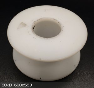
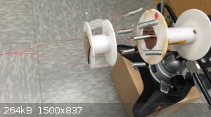
A couple of empty spools sacrificed their lives for the cause of science, as seen below. Six holes were drilled around the periphery of the spools
to enable the wire and springs to pass through.
 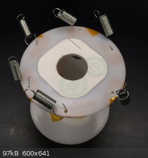
A couple of springs were set up for tension on the center conductor:
And a copper “washer” was soldered to a length of copper pipe on a hot plate.
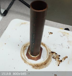
Here the pipe is inserted through on one of the spools, on which it rotates freely. The pipe is clamped into the vise behind the spool. The washer
on front of the pipe keeps the spool captive, and the springs maintain tension on the wires. Here we have a center conductor, with six wires spaced
around it.
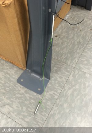
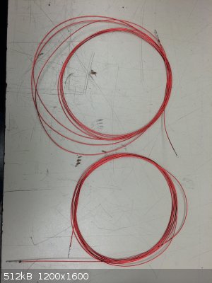
At the other end the wires are threaded through the spool, and twisted together at the ends. The spacing between the twist and the spool should be
maintained at about 7”. This is easier if you have a friend to help you with this, as the wire that I used was 9’ long.
If you do it by yourself, you’ll have to walk back and forth every five turns, to keep the spool spaced properly (ask me how I know).
Using a clever trick of photography, I made it look like I actually did this!
Actually, I did do it; it only took about 20 minutes to twist all nine feet of it. It didn’t take as long as I thought it would. In fact, it was
so much fun that I made two of them!
To be continued...
|
|
|
WGTR
National Hazard
Posts: 971
Registered: 29-9-2013
Location: Online
Member Is Offline
Mood: Outline
|
|
Now here is the next step. I took each one of these wires, and folded them over twice, cutting the loops at each end. This left a total of eight
strands, four from each wire. Then, four strands each where taken and braided into approximately two foot lengths, leaving two braided cables of
four strands each. If you have a younger sister, get her to do this for you. Pay her if you must. She will be way better at this braiding thing
than you. As for me, I have a trained feline. She does a good job, and I can bribe her with tuna.
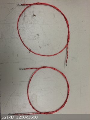
Maybe you can also see why it’s important to use the heat-strippable version of wire. There are 28 strands in each cable.
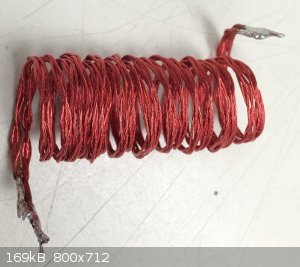
After all that work we can have a little bit of fun now. Both cables were soldered together in parallel, and wound around a dowel, both cables
side-by-side. This left a nice (but floppy) inductor, with some rather nice specs:
Ls=0.83uH , Rs=6.9mohms @ 1kHz
Ls=0.83uH, Rs=9.6mohms@ 100kHz
At 100 kHz, we see that the AC resistance is only 0.0096 ohms, which is only marginally higher than the 0.0069 ohms at 1kHz. Normally because of
skin effect the AC resistance increases dramatically, but here it does not, because the individual strands are thin enough for the frequency (32 AWG
at 100kHz), and each strand spends an equal amount of time in the cable as it does on the outside edge, cancelling the circulating currents in the
wire.
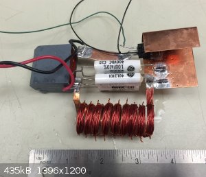
Because this coil structure is too soft, a ribbon was cut out of copper sheet, and the braided wire was tied on with pieces of enameled wire. Each
end of the coil was soldered to the copper ribbon, and the finished coil was tested.
Ls=0.60uH, Rs=2.9mohms @ 10kHz
Ls=0.55uH, Rs=8.9mohms @ 100kHz
Here I goofed and measured at 10kHz instead of 1kHz, but still the dramatic affect of having the copper ribbon in parallel with the coil is
illustrated. Low frequency AC resistance improves because of the bulk copper in the ribbon, but at 100kHz the resistance is unchanged from the
earlier coil configuration. This is because at 100kHz, the ribbon’s AC resistance is so much higher than the braided cable, it is electrically not
part of the circuit.
The coil was installed in a basic type of circuit as seen below. It is driven only on one half-cycle, and uses a single FS70UM mosfet. The FET is
driven directly from a signal generator, and is driven rather poorly, I should add. The signal looks more like a triangular wave on the gate,
instead of the desired square wave.
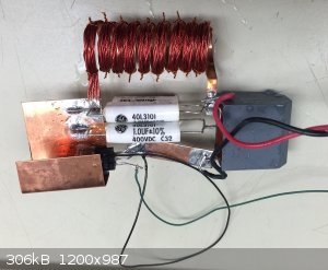 
At 10V on the supply, 0.3A is drawn at resonance (110kHz), unloaded. In a full-wave configuration, this would be about 0.6A, similar to what Cheddite
Cheese is seeing. There is a key difference in the way our respective tank coils respond to a load, and when I have time, I throw some math out
there to show why. It’s getting rather late right now, though.
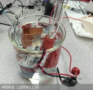
Anyway, here I have the circuit operating in a beaker of DI water. The water has to be very clean, as you don’t want it to conduct electricity,
only heat. With this type of a setup everything in the circuit was kept cool, even while dumping 30-40 watts into a piece of steel. The piece of
steel that I was heating was sitting on a piece of firebrick contained within a test tube, which you can see in the picture. I’ll have to run some
numbers, I may be able to bump this up to a 100 watts. Right now I’m limited by the power supply I’m using.
|
|
|
IrC
International Hazard
Posts: 2710
Registered: 7-3-2005
Location: Eureka
Member Is Offline
Mood: Discovering
|
|
No several orders have not yet left the mainland postal system. Yet out of several orders the same day a few got here days ago (50 caps today), like
my ten IRFP264's. Not going to touch a single one until I get all parts (including the dozen perfect sized heat sinks I found at a good price) in one
location on my bench. I will never understand how some orders get here in 6 or 7 days yet 2 weeks later some still show 'processed through' one or
other location in China. Then a week later they show up in N.Y. where they sit yet another week before heading to the windy city where they piss
around for 2 or 4 days. Usually at that time it's still 3 or so days away from my PO. It must be the way they ship. E-packet always takes a week in NY
at what I think is a customs center. Others blast right here from China in a week from the purchase. Cheddite Cheese has me tempted to junkbox using a
couple my 264's but I lack the correct DC input choke and heat sinks. If one reads the theory comments by WGTR one can see it is risking the new fets
to not have enough inductance in the choke. I am using an 80 uH one which no doubt is partly the reason I keep blowing fets, 4 amp ratings being most
likely the other reason.
WGTR "The 130uH inductor is needed, not so much for power supply filtering, but to limit the Vds rise-time on start-up. Without it full voltage will
get applied to both MOSFETs (which are already "ON"), with the MOSFETs acting as the primary current-limiting (and power dissipating) devices."
"Science is the belief in the ignorance of the experts" Richard Feynman
|
|
|
woelen
Super Administrator
Posts: 7976
Registered: 20-8-2005
Location: Netherlands
Member Is Offline
Mood: interested
|
|
Finally some of my stuff arrived. Two IRFP250's, and some other assorted stuff, and a small PCB board on which I can solder the components. I added
small heat sinks, which I ordered elsewhere. The IRFP250's are bigger than I expected, my heatsinks actually are quite small.
Before doing induction heating, first I'll try an experiment with a transformer (I have one with 2500 turns around a rectangular core) and at the
primary I have to make my own coil. I use stereo loudspeaker wire (0.75 mm2 with a red and a transparent wire connected to each other) for
that and connect the red wire at one end to the transparent wire at the other end. This is my center tap, the free transparent wire and free red wire,
at opposite ends then are the other two taps. In this way you always certainly will have both coils turned around in the same direction.
I am still waiting for my IRFP264's to arrive and I hope that none of the IRFP250's will be blown out. I only have two of them.
|
|
|
Metacelsus
International Hazard
Posts: 2531
Registered: 26-12-2012
Location: Boston, MA
Member Is Offline
Mood: Double, double, toil and trouble
|
|
Video:
https://www.youtube.com/watch?v=wVu8UY9fJdA
|
|
|
IrC
International Hazard
Posts: 2710
Registered: 7-3-2005
Location: Eureka
Member Is Offline
Mood: Discovering
|
|
https://github.com/joshcam/ReactorForge
https://www.youtube.com/watch?v=0vL-sArhmkI
Induction heating in general, not necessarily all on ZVS, but he does have some experiments using the basic ZVS design.
https://www.youtube.com/watch?v=pVYMLnXW9uo&feature=play...
http://www.rmcybernetics.com/projects/DIY_Devices/index.htm
Resonant Frequency Calculator
http://www.deephaven.co.uk/lc.html
Single layer air core inductor calculator
http://www.circuits.dk/calculator_single_layer_aircore.htm
Single-Layer Helical Round Wire Coil Inductor Calculator
http://hamwaves.com/antennas/inductance.html
Looked at the video Cheddite Cheese made (good work) and found a few more videos from links off his video page. On another note:
| Quote: Originally posted by papaya | | Don't be excited too much - works only on ferromagnetics. copper will not get too hot for example - actually the effect is not from inductive currents
heating.. |
Then you will have to explain this video:
https://www.youtube.com/watch?v=zw_SrGU2iYs
I would be thinking about the consideration of eddy currents and simple I*I*R effects.
No I'm not trying again to figure out how to get superscripts to work. This board software hates me I'm sure of it. Just read it I squared times R.
http://en.wikipedia.org/wiki/Joule_heating
Here is a link from the video on melting Cu.
http://www.mindchallenger.com/inductionheater/
"Science is the belief in the ignorance of the experts" Richard Feynman
|
|
|
woelen
Super Administrator
Posts: 7976
Registered: 20-8-2005
Location: Netherlands
Member Is Offline
Mood: interested
|
|
Before I use my high power devices, I did some playing around with a miniature version of the ZVS driver, just to get some experience with this stuff
before I start with the real thing, and I must say that this works quite well. If something goes wrong with this lighter/smaller stuff, then the
damage is less severe.
I have some IRF540's lying around. These are not nearly as powerful as the IRFP250 and IRFP264, but they are decent devices in a TO-220 package. I
used two BA159 diodes and 12V zeners (normal small zeners) and two 330 Ohm power resistors and a coil from an old power supply. The primary windings
are 2x5 turns, around the core of a small flyback transformer from Nokia with unknown number of turns in the secondary winding and unknown primary
windings (it has 10 or so connections, I do not use any of them, except one which is the ground end of the secondary winding).
There is no hissing and no corona discharge, but I can light a glass ampoule with neon gas in it and I also can light a similar glass ampoule with
helium gas in it. The ampoules have a length of 10 cm and no internal electrodes, they are just sealed glass ampoules with some gas in them. I simply
turn some metal wire around one end of the glass ampoule and around the other end and connect this with the two poles of the flyback transformer. This
gives a bright nice orange glow for the neon ampoule and a fainter pinkish/orange glow with the helium ampoule. The ampoule is this one (I already
have this some time, ordered from this chinese eBay seller as a nice and robust sample of neon):
http://www.ebay.nl/itm/281267028284?ssPageName=STRK:MEWAX:IT...
I never had it glowing before, but with this little experiment I could witness the nice orange glow.
This shows that I have at least a few kV, probably 5 kV or so, given the length (and the thickness of glass) of the ampoules.
I use small heat sinks with heat transfer paste on the transistors (20x30 mm) and when I have the glass tube lit for a few minutes, then these
heatsinks are warm, but not hot.
These are my first little steps in home made high voltage drivers, more will follow with more powerful stuff 
|
|
|
IrC
International Hazard
Posts: 2710
Registered: 7-3-2005
Location: Eureka
Member Is Offline
Mood: Discovering
|
|
http://www.ebay.com/itm/321352599471?ssPageName=STRK:MEWNX:I...
This factory made board arrived today. I built a Cu tubing coil similar to the one in pic heating metal on auction page except diameter is around 2.5
times the diameter of the tubing coil in the picture. But at 14 volts it refuses to take off at high enough power. Merely warms metal but no glow.
Years ago I built a variable regulated supply that adjusts from 0.7 to 50 volts and can supply 50 amperes at 15 volts, 35 amperes at 50 volts. Going
to dig it out of storage this week and dust it off I guess. Seller states 12 to 36 volts but at 12 volts it drives a flyback well for good output
sparks but no cigar on metal melting. Will have to try my tubing coil at 25 volts or so and see how it does. Or maybe make a smaller diameter coil. My
tubing is a little too large to easily coil it that small however. Just an FYI if anyone buys this board, they may state 12 volts minimum but I am
sure 24 is going to be the minimum if any decent power level is needed. Possibly it would have heated better at 12 to 15 volts supply if I had made
the tubing coil as small in diameter as the one on the page. Could be too much inductance in my tubing coil for such a low supply voltage but 12 to 15
V at 35 amps is the only large supply on my bench at the moment. So far it appears I'm having better luck with my home made circuits with 1 uF 630
volts for the capacitor.
Another thing I notice in studying the coil waveform is it does not appear the coil is 'ringing' as it should, i.e., the other half of the waveform is
not being symmetrically recreated by back EMF as one would desire if building a fairly clean RF amplifier. Whether it is due to insufficient
capacitance or the way the ZVS circuit operates I cannot tell. However I suspect both have an effect with I believe the too small amount of
capacitance being the main factor. This board uses 0.66 uF yet my own circuit using 1 uF appears to operate better. Just a guess but L/C ratio is
important but not being investigated well in this design. The energy stored on each half cycle in the magnetic field needs to be closer to that stored
in the electric field in the capacitor. Perhaps design changes which consider this would increase performance.
"Science is the belief in the ignorance of the experts" Richard Feynman
|
|
|
Metacelsus
International Hazard
Posts: 2531
Registered: 26-12-2012
Location: Boston, MA
Member Is Offline
Mood: Double, double, toil and trouble
|
|
My coil's inductance is ~10 uH, and I'm using a 2.72 uF capacitor (four 0.68 uF caps in parallel). This seems to give good results. I'm also running
off 24 volts (but I may try 36 soon!)
|
|
|
IrC
International Hazard
Posts: 2710
Registered: 7-3-2005
Location: Eureka
Member Is Offline
Mood: Discovering
|
|
This makes 2 of us coming to this conclusion thus far. I wondered about it when I first looked at the design using IIRC 0.68 uF, before I tried the
circuit myself. I am guessing your even higher C means yours is working better than mine. Guess I'll risk some Mosfets and see how high I can go while
staying within reason. Also forgot to mention my factory board with my way too large tubing coil is running around 114 KHZ. Damn Cu tubing is getting
expensive but I must get a 50' roll of some skinnier stuff. My 3/8' tubing sucks trying to coil a small diameter with 9 or thereabouts turns. Not
being able to quickly obtain a roll of say 1/4 " and 1/8" cu tubing right now (car needs rear differential and it's too hot to put the used one I
found in right now) I gave up on heating ideas and went back to flybacks for awhile. If you study the schematics Tim posted on page 1, these are what
I call 'typical circuits'. The kind or similar I have toyed with for decades.
I will never go back to one like it again whether 555 driven bipolars, fets, u name it; or oscillator types using all of the previous or even
choppers. Or whatever comes to mind. Even tube circuits. Done. I am so amazed with the efficiency of this ZVS driver. At 600 ma 14 V input I can draw
an arc from 2 inches away which immediately goes to a metal melting thick arc with power input rising to an ampere at most. I have tried many
variations with this same flyback at input currents of several amperes and overheating devices that produced neither the potential nor the power in
the arc I am seeing right now. The efficiency and ability to transfer raw energy into a flyback at very low power input is beyond anything I for one
have seen in simple low parts count circuitry. Using this driver circuit design for the heart of a stun gun would produce a very dangerous no longer
non lethal self defense device of this I have no doubt.
Having taken many high end commercial models apart completely reverse engineering them in the past I am amazed not one has so far used the principle
of the ZVS driver. They all use the oscillator type of what I now term forever the 'typical circuits' driving a spark gap and multiplier circuit. I am
going to dig out my old 300 KV stun gun and rip the board out to replace it with a ZVS design for the base high voltage source with that driving the
spark gap and multiplier. I get the feeling the output factory components will not be able to handle this new input even when run from a couple
Alkaline 9 volt batteries. May well end up having to redesign and rebuild the gap and multiplier output sections as well.
 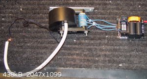
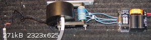
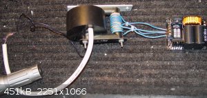
Tossed this together on my bench quick and dirty just to take a couple pics. The flashlight served the useful purpose of stopping the big fat flexible
HT wire from moving around. Circuit does a fair job setting my bench carpet on fire and the arc will go further still melting copper wire. At this
time voltage input is 13.8 volts and I ~= 900 ma. Don't remember where I got these great flybacks, some surplus outlet where I bought a dozen at IIRC
$8 each. Best ones I have found, easy to take apart core and create various circuit designs with. Great output in terms of high voltage and current.
[Edited on 7-24-2014 by IrC]
"Science is the belief in the ignorance of the experts" Richard Feynman
|
|
|
| Pages:
1
2
3
4
5 |


