Metacelsus
International Hazard

Posts: 2531
Registered: 26-12-2012
Location: Boston, MA
Member Is Offline
Mood: Double, double, toil and trouble
|
|
Spot Welder
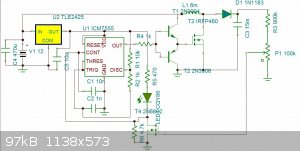
I have designed and (mostly) built a portable spot welder. It uses a boost converter to convert 12V DC ifrom a lead-acid battery into 330 V DC
(maximum), which charges a 15 mF (yes, milli, not micro) electrolytic capacitor bank.
Schematic (the regulator should be an LM7810 and the diode should be a UF1006, but the simulator didn't have those):
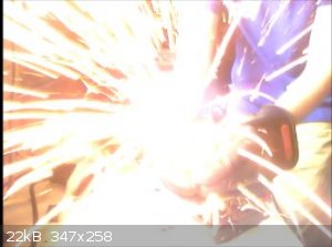
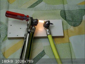
Results (at 200V):
I tried (with my hands) to break the weld. It was surprisingly strong, but I eventually managed to snap it at what I estimate was about 15 pounds of
force.
[Edited on 1-7-2014 by Cheddite Cheese]
|
|
|
Brain&Force
Hazard to Lanthanides
Posts: 1302
Registered: 13-11-2013
Location: UW-Madison
Member Is Offline
Mood: Incommensurately modulated
|
|
LOL, with the last photo it looks like you welded a MASSIVE nail to your window.
Can you show us the spot welder, and give its dimensions? This is pretty interesting.
At the end of the day, simulating atoms doesn't beat working with the real things...
|
|
|
Metacelsus
International Hazard
Posts: 2531
Registered: 26-12-2012
Location: Boston, MA
Member Is Offline
Mood: Double, double, toil and trouble
|
|
It's still mostly on a breadboard, so the dimensions are not yet fixed. I'll upload a picture of the spot welder soon (tonight or tomorrow).
|
|
|
froot
Hazard to Others
Posts: 347
Registered: 23-10-2003
Location: South Africa
Member Is Offline
Mood: refluxed
|
|
Nice project. Do you really need the drivers T1 and T2 to drive the mosfet? I'm asking because I'm busy with designing circuitry using power mosfets
and have chosen to drive them directly from op-amp level outputs similar to that of the 555 timer. Can you do me a favour on your breadboard, connect
the 555 timer output directly to the mosfet gate of T3 and see if it works the same.
Edit, leave R4 on the putput line.
[Edited on 1-7-2014 by froot]
We salute the improvement of the human genome by honoring those who remove themselves from it.
Of necessity, this honor is generally bestowed posthumously. - www.darwinawards.com |
|
|
jock88
National Hazard
Posts: 505
Registered: 13-12-2012
Member Is Offline
Mood: No Mood
|
|
Thats a dangerous yoke. Mind yourself.
|
|
|
Metacelsus
International Hazard
Posts: 2531
Registered: 26-12-2012
Location: Boston, MA
Member Is Offline
Mood: Double, double, toil and trouble
|
|
@Froot. Yes, I do need them.
I originally thought I didn't, but without them the turn-on and turn-off times were too long, which meant that the MOSFET overheated very quickly.
|
|
|
Metacelsus
International Hazard
Posts: 2531
Registered: 26-12-2012
Location: Boston, MA
Member Is Offline
Mood: Double, double, toil and trouble
|
|
Video of the spot welder in action:
https://www.youtube.com/watch?v=Qh42eoekR3E
[Edited on 1-7-2014 by Cheddite Cheese]
|
|
|
Brain&Force
Hazard to Lanthanides
Posts: 1302
Registered: 13-11-2013
Location: UW-Madison
Member Is Offline
Mood: Incommensurately modulated
|
|
Come on! Why'd you have to take my idea for a YouTube channel name? 
That's what I knew would happen when I began watching the video. Liked and subscribed.
At the end of the day, simulating atoms doesn't beat working with the real things...
|
|
|
macckone
International Hazard
Posts: 2159
Registered: 1-3-2013
Location: Over a mile high
Member Is Offline
Mood: Electrical
|
|
I use a similar driver for my ozone generator.
I found that installing the mosfet attached directly to
the 555 oscillator caused the 555 oscillator to overheat.
I also used pull-up and pull-down resistors on the transistors
to improve stability.
|
|
|
froot
Hazard to Others
Posts: 347
Registered: 23-10-2003
Location: South Africa
Member Is Offline
Mood: refluxed
|
|
Thanks Cheddite Cheese, the only thing I can speculate for this is that T1 and T2 amplify the slew rate of the 555 output thereby reducing t(on) and
t(off).
One more thing, how did you calculate the value of L1?
We salute the improvement of the human genome by honoring those who remove themselves from it.
Of necessity, this honor is generally bestowed posthumously. - www.darwinawards.com |
|
|
Metacelsus
International Hazard
Posts: 2531
Registered: 26-12-2012
Location: Boston, MA
Member Is Offline
Mood: Double, double, toil and trouble
|
|
I measured it; I didn't know the magnetic permeability of the core, so I could only estimate the number of windings I needed. It turned out to be 6
mH. Of course, the exact value isn't critical to the operation of the circuit.
|
|
|
Varmint
Hazard to Others
Posts: 264
Registered: 30-5-2013
Location: Near Atlanta, GA
Member Is Offline
Mood: No Mood
|
|
Cheddite Cheese:
Obviously there is quite a bit of fun-factor in dumping joules into a load (sparks of any kind tend to be fascinating), but those sparks also indicate
inefficiency for spot welding.
A better approach would be to disassemble a MOT and install a low turn count secondardy winding to supply low voltage at high current.
If you study the spot welders available on the market or used in industry, the primary feature is wide contact copper inserts, usually carried on long
large diameter high conductivity arms.
The arms serve two purposes, the obvious one is to extend the reach of the contacts so larger work pieces can be welded, but the secondary benifit (no
pun intended) is to provide some "spring" to the assembly so that as material is displaced by the heat and pressure, intimate contact is maintained
with the workpiece.
In essence, sparks are a bad sign, the balls of molten material and once gaseous "spray" force you to clean up the workpiece before paint or other
finish coatings may be applied.
The ideal weld is achieved by a balance of pressure (a function of the contact sizes and applied pressure, and the duration of the applied current.
The most advanced industrial welders have current dwell settings, even more advanced is the ability to control the current profile over time in order
to get the best initial tack followed by sufficient current to guarantee a good intermingling of the semi-molten workpieces.
The current of course depends on workpiece thickness and overall conductivity. If you were to take a fixed current and apply it to the workpiece for
the "proper" time and contact pressure, the first weld will tend to have greater penetration and heat injection to the suppounding work, while
subsequent adjacent welds will have less penetration as the workpiece is already intimately electrically bonded, effectively "stealing" current from
the next weld.
In industry this is most times handled by the current profile being initially comparatively low (not by large amounts), and increasing for subsequent
welds so the actual penetration tends to average out to be the same.
None of this is under your control when dumping stored energy into the workpiece. Unless you have a high current contactor in the circuit, using the
contacts themselves as the "switch" to deliver current will always result in large losses in energy and penetration simply because the surface is
blown away in a shower of sparks and you'll never get sufficient repeatability to guarantee any weld integrity.
Fortunately (or unfortunately, it's not an exciting job), I've had the opportunity to create hundreds of thousands if not millions of spot welds in an
industrial setting. We used to test our welds on sample materials (cutoffs from sheet metal shears) and after opening up the work so it could be
grasped by the test gear, we'd use guaged hydraulics to determine the force required to separate the work.
A proper weld never failed at the weld itself, the pulling action of the test fixture would tear the unwelded material away from the welded areas,
proving the weld itself was far stronger then the material it was created from. This of course is based on the fact that the intense heat and
comparatively rapid cooling of the spot weld tended to harden the worked material, leaving the softer virgin material. Again, this localized
hardening isn't something you can could on with a sparky discharge, it requires the proper current, time, and pressure.
You have an apparatus capable of spectacular displays of the effects of stored energy, but a spot welder it isn't. Without wholesale changes it will
never be effective as anything remotely like a spot welder.
Get yourself some good sized heavy duty xenon flash discharge tubes to experiment with, and use a high voltage trigger circuit to initiate the
ionization. I've bleached newspaper nearly white using the discharge from suitable lamps using a supply like yours, the flash is so brief the ink
vaporizes before it can transfer enough heat to the paper fibers to initiate combustion.
Wear eye protection no matter what you are doing with your supply though, hot molten balls of metal or shards of glass are no fun...
DAS
[Edited on 3-7-2014 by Varmint]
|
|
|
Metacelsus
International Hazard
Posts: 2531
Registered: 26-12-2012
Location: Boston, MA
Member Is Offline
Mood: Double, double, toil and trouble
|
|
Thanks for the explanation.
I have two MOTs lying around, so maybe I will make a true spot welder.
|
|
|
wish i had a kraken!!!
Hazard to Others
Posts: 157
Registered: 22-3-2012
Member Is Offline
Mood: No Mood
|
|
My MOT high AMP trans.
|
|
|
phlogiston
International Hazard
Posts: 1375
Registered: 26-4-2008
Location: Neon Thorium Erbium Lanthanum Neodymium Sulphur
Member Is Offline
Mood: pyrophoric
|
|
That video demonstrated nicely that you need to clamp the two items together with pressure and then apply current, rather than charge the caps and
lightly touch them together.
Nice shower of sparks, no weld.
-----
"If a rocket goes up, who cares where it comes down, that's not my concern said Wernher von Braun" - Tom Lehrer |
|
|


