| Pages:
1
..
3
4
5
6
7
..
9 |
Varmint
Hazard to Others

Posts: 264
Registered: 30-5-2013
Location: Near Atlanta, GA
Member Is Offline
Mood: No Mood
|
|
Looks like pin 5 of the 555 is grounded, it should go to ground through a capacitor, I think you said you had a 0.022uF. Beyond that, I can't see
enough in the critical area around pins 6 and 7, and which wires go to the pot.
You should be able to revisit any of the 555 websites, find the astable configuration, and set it up exactly as you see it there.
|
|
|
Magpie
lab constructor
Posts: 5939
Registered: 1-11-2003
Location: USA
Member Is Offline
Mood: Chemistry: the subtle science.
|
|
Yes! That was the problem. From pin 5 I had the 0.022µF cap connected to ground but I also had a wire going from pin 5 directly to ground. Once
that wire was removed it performed as before. Thank you very much. Varmint! 
The single most important condition for a successful synthesis is good mixing - Nicodem
|
|
|
Magpie
lab constructor
Posts: 5939
Registered: 1-11-2003
Location: USA
Member Is Offline
Mood: Chemistry: the subtle science.
|
|
My stepper motor stirrer assembly is nearly complete. I now have the driver circuit board mounted in an enclosure and a 6' long cable wired to it.
The cable is a 4-wire, 22 gauge, security cable available from Home Depot by the foot. All wire connections have been shrink-wrapped to protect them
from corrosive atmospheres. The 4-wire plug connection to the motor is as yet unprotected as I am not sure how best to seal this. I have thought of
applying silicone caulk. What do forum members recommend?
I have a digital tachometer with LED display on its way from China on a slow boat. When this is all assembled I will post a picture of the finished
product.
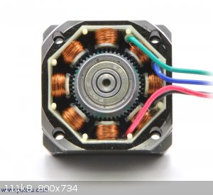
I found a nice picture of the inside of a bipolar stepper motor on the pololu site, as shown below. My understanding is that there are 2 stator
electrical winding phases, one represented by the black-green wire pair and the other by the red-blue wire pair. Each phase contains four
electromagnets, alternating around the circumference. Every pulse of the 555 timer triggers the driver to pulse one of the two phases, alternately.
The electromagnets also alternate in sense, ie, north and south, by the driver changing the current direction.
There are 50 teeth on the front permanent magnet (PM) of the rotor and 50 teeth on the back PM of the rotor (can't really see the back teeth in the
picture). These two magnets are of opposite, sense, ie, a north pole and a south pole, and their teeth are staggered with respect to each other.
The number of steps S of this motor per revolution equals the number of phases φ times the number of teeth, T. So,
S = φT = 2 x 50 x 2 = 200
Therefore, each pulse turns the rotor 1/200th of a revolution, or 1.8°.
Varmint, please correct me if I have made any errors.
[Edited on 30-12-2014 by Magpie]
The single most important condition for a successful synthesis is good mixing - Nicodem
|
|
|
Hellafunt
Hazard to Self
Posts: 65
Registered: 2-12-2014
Member Is Offline
Mood: No Mood
|
|
today at the thrift store i found an 110V AC rotisserie spit turner motor for $4.99. it is really strong but very slow, just under one RPM. could this
be of any use as an overhead mixer? i have not yet needed an overhead mixer, so i dont really know if such a slow mixer would be useless.
|
|
|
smaerd
International Hazard
Posts: 1262
Registered: 23-1-2010
Member Is Offline
Mood: hmm...
|
|
Magpie I believe you're understanding of stepper motors is correct  . This project
is awesome and I am impressed with your driver circuit. Do any of your IC's get hot after prolonged useage? . This project
is awesome and I am impressed with your driver circuit. Do any of your IC's get hot after prolonged useage?
|
|
|
Zombie
Forum Hillbilly
Posts: 1700
Registered: 13-1-2015
Location: Florida PanHandle
Member Is Offline
Mood: I just don't know...
|
|
I just wanted to chime in, and shake everyone hand for sharing this project.
This is something that benefits the entire community in all the right ways. If I have to make up a deserted island "guest book" I would also have to
include you fellas.
Thank you for sharing all of this.
They tried to have me "put to sleep" so I came back to return the favor.
Zom.
|
|
|
Magpie
lab constructor
Posts: 5939
Registered: 1-11-2003
Location: USA
Member Is Offline
Mood: Chemistry: the subtle science.
|
|
I have not detected any overheating, however, I have not actually put the stirrer to use yet. I don't believe the 555 timer is vulnerable to
overheating. The IC on the driver board comes with a heat sink.
I received the tachometer from China yesterday. I am planning to post pictures of the complete project along with itemized costs sometime later
today.
The single most important condition for a successful synthesis is good mixing - Nicodem
|
|
|
Magpie
lab constructor
Posts: 5939
Registered: 1-11-2003
Location: USA
Member Is Offline
Mood: Chemistry: the subtle science.
|
|
I completed the assembly of my stepper motor stirrer today. As indicated by the digital tachometer the available stirring speeds are 21 to 213 rpm.
It has a 6ft cable so that I can keep the power supply and driver electronics well out of my hood when using the stirrer. Shown below are some
pictures taken during final assembly. Also attached are the itemized costs, which totaled $64.36. I did hire some machinist labor to help me mount
the motor on the aluminum slab and attach the carriage bolt. This cost is not included on the Excel spreadsheet.
I had a lot of fun learning about stepper motors and how to use one for an overhead stirrer. With a more powerful motor and a larger power supply
voltage increased speed and torque would surely be possible. If you have any questions I will be glad to try and answer them.
components on perf board
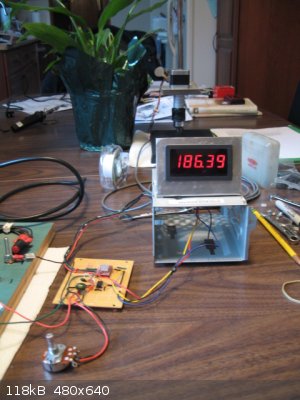
tachometer in operation
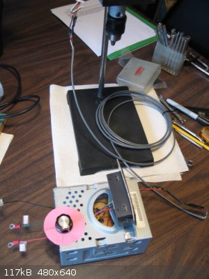
stepper stirrer final assembly
Attachment: Stepper Motor Stirrer Costs.xls (24kB)
This file has been downloaded 474 times
The single most important condition for a successful synthesis is good mixing - Nicodem
|
|
|
Zombie
Forum Hillbilly
Posts: 1700
Registered: 13-1-2015
Location: Florida PanHandle
Member Is Offline
Mood: I just don't know...
|
|
Spectacular thread.
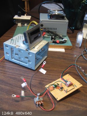
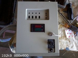
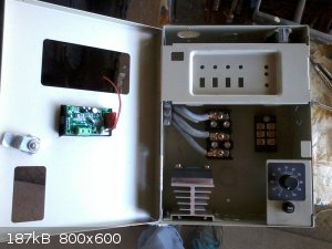
You can still fancy this up some using a "project box".
Something cheap from Ebay to stuff it all into. I'm attaching a pict of a boiler controller (distillation) I built using an Alarm Box I bought for
19.00USD/free shipping. Just to show the point... These are pre completion.
Great build Sir!
They tried to have me "put to sleep" so I came back to return the favor.
Zom.
|
|
|
Magpie
lab constructor
Posts: 5939
Registered: 1-11-2003
Location: USA
Member Is Offline
Mood: Chemistry: the subtle science.
|
|
I have decided to upgrade my stepper motor mixer using a huge motor: Oriental Motor's PKP296D45AA, with 85mm frame. To drive this I have a a4988
driver, Polulo CVD245BR-K . This will be supplied with a regulated 24vdc.
I need to provide a pulse. What I'm planning to use is a 555 astable timer circuit. The pot R1 will be 100KΩ, R2=1KΩ, C1=0.22µF, and the
capacitor from pin 5 to ground = 0.022µF. VCC will be 6vdc. This is the same timer circuit I have in use for my small stepper motor mixer.
Please comment on my choice of timer circuit.
The single most important condition for a successful synthesis is good mixing - Nicodem
|
|
|
Magpie
lab constructor
Posts: 5939
Registered: 1-11-2003
Location: USA
Member Is Offline
Mood: Chemistry: the subtle science.
|
|
The 555 timer circuit that I have used for years does not work anymore. I have been troubleshooting all day with no success.I have done the
following:
1 Replaced the 555 IC twice.
2. Confirmed the values of R1 and R2.
3. Rewired the 555 IC portion of the circuit.
4. VCC voltage of 6vdc confirmed.
Any help to fix this circuit will be highly appreciated.
The single most important condition for a successful synthesis is good mixing - Nicodem
|
|
|
Melgar
Anti-Spam Agent
Posts: 2004
Registered: 23-2-2010
Location: Connecticut
Member Is Offline
Mood: Estrified
|
|
While it's kind of a cop-out answer, at $6 each, I just use an Arduino whenever I need to do anything even slightly complicated. The main thing
that's nice about them is that if you want to change just about anything, or add some needlessly-elaborate feature, it's super easy. And of course,
type in just about any circuit and the word "arduino" and it's virtually assured that something will come up, with really easy instructions:
http://howtomechatronics.com/tutorials/arduino/how-to-contro...
The first step in the process of learning something is admitting that you don't know it already.
I'm givin' the spam shields max power at full warp, but they just dinna have the power! We're gonna have to evacuate to new forum software!
|
|
|
Magpie
lab constructor
Posts: 5939
Registered: 1-11-2003
Location: USA
Member Is Offline
Mood: Chemistry: the subtle science.
|
|
Thanks for the suggestion, Melgar. I had no idea Arduinos were so cheap.
I have sent for components to make a circuit that will test a 555 timer IC.
I am contacting the electronics instructor at my local college for help.
The single most important condition for a successful synthesis is good mixing - Nicodem
|
|
|
carrant
Harmless
Posts: 39
Registered: 19-3-2015
Location: Dallas, Tx
Member Is Offline
Mood: No Mood
|
|
Thanks to all who posted regarding building an overhead stirrer!
I built an overhead stirrer using an Arduino Nano, DRV8825 (w/ heatsink), NEMA 17, and a relay for the fan.
Basic operation -
Rotary encoder to increase/decrease speed.
Rotary encoder button
* single click - change rotation direction
* double click - turn fan on/off
* hold button - idle the motor and reset the runtime clock
If the internal temp of the box exceeds 55C (131F) then the fan is forced on until the temp drops below a threshold 35C (95F). I'm not sure of the
high/low temps yet, but my garage in a Texas Summer is well over 100F.
Here is a link to a short video of it
https://youtu.be/tjacD4AK9Ro
Here is a link to the Arduino source
https://github.com/carrant/overheadstirrer/tree/master
Parts list
Local stores (In Dallas, Texas, USA: BGMicro, Tanner Electronics, Microcenter, Home Depot)
* Arduino Nano
* Project box
* 100uF caps
* 100nF caps
* 27K resistors
* 12V power supply
* 12V 40mm fan
* standoff, screw, nuts
* hookup wires
* jumper wires
* grommets
* NEMA 17 12V stepper
* 1/2" x 36" AL rod https://www.homedepot.com/p/Everbilt-1-2-in-x-36-in-Aluminum...
* Electrical brackets
Online orders
* perfboard https://www.ebay.com/itm/10pcs-5cm-x-7cm-PCB-Prototyping-Per...
* 16x2 LCD https://www.ebay.com/itm/New-Blue-IIC-I2C-TWI-1602-16x2-Seri...
* rotary encoder https://www.ebay.com/itm/10pcs-12mm-Rotary-Encoder-Push-Butt...
* solid state relay 1ch https://www.ebay.com/itm/5V-DC-1-Channel-Solid-State-Relay-B...
* drv8825 https://www.ebay.com/itm/5-PCS-DRV8825-3D-PRINTER-STEPPER-MO...
* DHT11 https://www.ebay.com/itm/1PCS-Arduino-DHT11-Temperature-and-...
* NEMA 17 bracket https://www.amazon.com/gp/product/B071NWWB7Z/ref=oh_aui_deta...
* 5mm to 7mm shaft coupler https://www.amazon.com/gp/product/B06X9WF7BG/ref=oh_aui_deta...
Issues -
Reading the DHT11 temp sensor is troublesome. If interrupts are disable while reading the DHT11, the stepper timer will miss resulting in jitter. If
interrupts are not disabled the DHT11 read will likely timeout. I tried to read it in the ISR which works slightly better but is still problematic. I
also tried a DHT11 lib that uses an ISR for reading but did not have any improvement.
The rotary encoder's button is awkward to click. I suspect the case is a bit too thick, or the rotary encoder's quality isn't great.
|
|
|
GrayGhost-
Hazard to Self
Posts: 61
Registered: 31-10-2017
Location: Argentina
Member Is Offline
Mood: No Mood
|
|
Im use a chip chinese type Dremmel, with stainles steel like agitator, and variable speed incorporated, for minor speed use in serie a lamp type
Edison (incandescent) 40 or 60 W and work fine.
|
|
|
Magpie
lab constructor
Posts: 5939
Registered: 1-11-2003
Location: USA
Member Is Offline
Mood: Chemistry: the subtle science.
|
|
Quote: Originally posted by GrayGhost-  | | Im use a chip chinese type Dremmel, with stainles steel like agitator, and variable speed incorporated, for minor speed use in serie a lamp type
Edison (incandescent) 40 or 60 W and work fine. |
I like this. But do you have sufficient torque to drive a 2.5cm agitator blade at 700 rpm? This would be needed to suspend iron fines for a making
an amine from nitrobenzene. Also other reactions need this amount of torque. Also it must be capable of running continuously in some cases.
[Edited on 30-12-2017 by Magpie]
The single most important condition for a successful synthesis is good mixing - Nicodem
|
|
|
GrayGhost-
Hazard to Self
Posts: 61
Registered: 31-10-2017
Location: Argentina
Member Is Offline
Mood: No Mood
|
|
| Quote: Originally posted by Magpie | | Quote: Originally posted by GrayGhost- | | Im use a chip chinese type Dremmel, with stainles steel like agitator, and variable speed incorporated, for minor speed use in serie a lamp type
Edison (incandescent) 40 or 60 W and work fine. |
I like this. But do you have sufficient torque to drive a 2.5cm agitator blade at 700 rpm? This would be needed to suspend iron fines for a making
an amine from nitrobenzene. Also other reactions need this amount of torque. Also it must be capable of running continuously in some cases.
[Edited on 30-12-2017 by Magpie] |
Nop, my agitator is wire, but running several hours. For more torque im thinking in use washing machine motor.
|
|
|
Magpie
lab constructor
Posts: 5939
Registered: 1-11-2003
Location: USA
Member Is Offline
Mood: Chemistry: the subtle science.
|
|
That sounds like huge overkill for motor size. Also, how would you control the speed?
I recommend a stepper motor. Even NEMA 17 has mucho torque. You do have to provide electronics for power and speed control, however.
The single most important condition for a successful synthesis is good mixing - Nicodem
|
|
|
GrayGhost-
Hazard to Self
Posts: 61
Registered: 31-10-2017
Location: Argentina
Member Is Offline
Mood: No Mood
|
|
| Quote: Originally posted by Magpie |
That sounds like huge overkill for motor size. Also, how would you control the speed?
I recommend a stepper motor. Even NEMA 17 has mucho torque. You do have to provide electronics for power and speed control, however.
|
Well is a future project, motor have to speed, 300 and 2800 rpm, I thinking use 300 rpm with mechanical reduction ( ghetto system) bycicle parts.
I have many adversities, i am poor, i am Marrieddddd, i am sudamerican and i am alone with my ideas and projects, and for last i am blacksmith, no
professional chemist. But i happy for make essay and experiments .
Thank you for you interest.
|
|
|
Magpie
lab constructor
Posts: 5939
Registered: 1-11-2003
Location: USA
Member Is Offline
Mood: Chemistry: the subtle science.
|
|
diddi, aga, varmint, et al,
I have purchased a Zyltech NEMA 23 stepper motor with Toshiba TB6600HG driver. Could someone please tell me how to connect the two. I have attached
a scan of the terminal configurations.
Attachment: Scan.pdf (185kB)
This file has been downloaded 363 times
The single most important condition for a successful synthesis is good mixing - Nicodem
|
|
|
Magpie
lab constructor
Posts: 5939
Registered: 1-11-2003
Location: USA
Member Is Offline
Mood: Chemistry: the subtle science.
|
|
Zyltech has provided a wiring diagram. However, I don't have a "breakout board," as such to provide the needed pulses. In the past I have used a 555
timer circuit.
The Zyltech breakout board has three wires coming from it that connect to the driver. They are labeled DIR, STEP, and +5V. These go to DIR-(DIR),
PUL, and PUL+(+5V), respectively. The +5V wire also goes to DIR = (+5V) on the driver.
Can anyone provide me with a 555 timer circuit diagram?
The single most important condition for a successful synthesis is good mixing - Nicodem
|
|
|
Twospoons
International Hazard
Posts: 1281
Registered: 26-7-2004
Location: Middle Earth
Member Is Offline
Mood: A trace of hope...
|
|
Something like this? I'm guessing, based on the pin labels, that the driver has opt-couplers on the inputs. The series resistors Ive shown may not be
needed, they may already be internal to the driver. 1k should be enough to limit the optocoupler current.
I'll leave it to you to work out the timing components on the 555.
I'm assuming EN has to be active to get anything to happen. The switch will let you change direction of rotation.
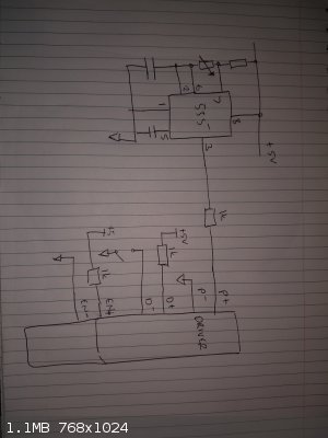
Argh - left off pin 4 of the 555 - connect it to +5V.
[Edited on 16-1-2018 by Twospoons]
[Edited on 16-1-2018 by Twospoons]
Helicopter: "helico" -> spiral, "pter" -> with wings
|
|
|
Magpie
lab constructor
Posts: 5939
Registered: 1-11-2003
Location: USA
Member Is Offline
Mood: Chemistry: the subtle science.
|
|
Thank you very much, Twospoons. I will be getting back to you as soon as I can (next day or two). Zyltech (a Chinese Co) is not giving much support.
The single most important condition for a successful synthesis is good mixing - Nicodem
|
|
|
Phosgenetimemachine
Harmless
Posts: 6
Registered: 25-1-2018
Member Is Offline
Mood: No Mood
|
|
slow,high torque....
Ice maker in standard home freezer
|
|
|
Magpie
lab constructor
Posts: 5939
Registered: 1-11-2003
Location: USA
Member Is Offline
Mood: Chemistry: the subtle science.
|
|
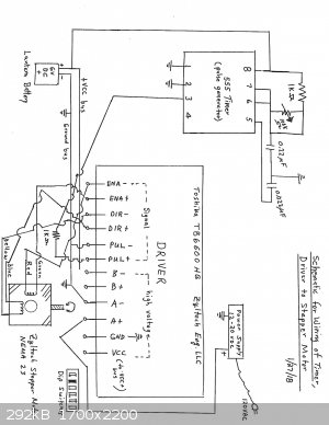
| Quote: Originally posted by Magpie | | Thank you very much, Twospoons. I will be getting back to you as soon as I can (next day or two). Zyltech (a Chinese Co) is not giving much support.
|
Based on your schematic I created a wiring diagram for my situation (see attached file.) I wired up the components and tried it out. It didn't work.
Please (anyone) provide recommendations to correct my wiring diagram.
The single most important condition for a successful synthesis is good mixing - Nicodem
|
|
|
| Pages:
1
..
3
4
5
6
7
..
9 |


