| Pages:
1
..
4
5
6
7
8
9 |
wg48
National Hazard

Posts: 821
Registered: 21-11-2015
Member Is Offline
Mood: No Mood
|
|
You seem to have the 6600 wired up wrong. Inputs connected as output. Outputs connected as power supply input. You have several power supply
connections not connected.
If you have a battery supply and a mains supply you have to be carfull not to put signals into unpowered devices or at incorrect voltages relative to
its supply vontage.
I suggest you look at an application note for the 6600 and look at a typical wiring diagram. You need to pay more attention the power supply
connections and which are inputs and which are outputs. Its all in the application note.
It may help if you draw your wiring diagram in less of a bird nest. Put arrows on the signal wires to indicate the signal flow.
Put arrows on pairs of wires like the drive connection to the motor to indicate the power flow. Try to arrange the functional blocks with say inputs
on the left and the ouputs on the right. That will help you in understanding what is going on.
You probably need to find a tried and tested diagram and use that.
[Edited on 28-1-2018 by wg48]
|
|
|
Magpie
lab constructor
Posts: 5939
Registered: 1-11-2003
Location: USA
Member Is Offline
Mood: Chemistry: the subtle science.
|
|
Thanks so much for your help, I am really getting desperate.
Quote: Originally posted by wg48  |
I suggest you look at an application note for the 6600 and look at a typical wiring diagram. |
I have tried to get technical help from Zyltech but have had no luck. Where would I find such an application note and typical wiring diagram?
If you could provide one or point me to one I would really appreciate that.
The single most important condition for a successful synthesis is good mixing - Nicodem
|
|
|
wg48
National Hazard
Posts: 821
Registered: 21-11-2015
Member Is Offline
Mood: No Mood
|
|
You probably have already pissed off Zyltech please don’t attempt to talk to them again as you may put them off trying to help anyone else.
Do you not know how to use Google??? If you don’t perhaps visit your locale library or an internet cafe and ask there or read a book called The
Internet for Dummies. Frankly you seem to be way out of your depth or perhaps you want to be spoon fed.
Ok here is a bit of spoon feeding: On the assumption you do know how to use google search for “TB6600 application note”. Read application note in
particular the wiring diagram at least three time or more. Identify the function of each connection and attempt to associate them with the connections
on your break out board.
I found the following thread when I googled “wiring up the td6600”
forum.arduino.cc/index.php?action=dlattach;topic=381679.0;attach=156278
|
|
|
Magpie
lab constructor
Posts: 5939
Registered: 1-11-2003
Location: USA
Member Is Offline
Mood: Chemistry: the subtle science.
|
|
First of all let me thank you profusely as I think we are well on the way to solving this problem that I have been struggling with for months.
| Quote: Originally posted by wg48 |
You probably have already pissed off Zyltech please don’t attempt to talk to them again as you may put them off trying to help anyone else.
|
No, I have only written them once and I have not seen their reply yet. The person really pissed off is me as up until now I have not been able to
find a wiring diagram.
Yes, I am way out of my depth and hence need direction from those experienced in such matters such as yourself. Isn't that what this forum is for?
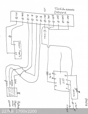
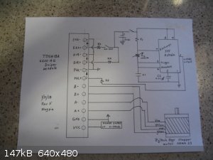
Attached is my revised wiring diagram for your review and comment. I know it is not completely correct as I had to make some guesses on the hookup to
the timer wiring (pulse generator). So, please correct any wiring errors that you see.
mucho gracias,
Don
The single most important condition for a successful synthesis is good mixing - Nicodem
|
|
|
wg48
National Hazard
Posts: 821
Registered: 21-11-2015
Member Is Offline
Mood: No Mood
|
|
Out of curiosity I did some more detailed research. I have several stepper motors as they are available from old photocopiers for free. The bigger the
photocopier the bigger the motors and incidentally power supplies, lenses, mirrors and a variety mechanical bits.
Apparently what you call a break out board I would call a module. They are available from ebay for as little as £6. Thats good for a dual channel
160W driver. Usually with little or no interface specification. They usually have a common mode isolated inputs ie opto isolated inputs. Hence the
two wire + and - inputs for each signal which are powered by the signals and not connected to the power supply of the module.
About your wiring diagram: You now have the inputs of the motor connected to outputs for a motor of the module. Assuming you have the correctly wired
one winding to phase A and the second winding to phase B and it is a two phase stepper motor I believe those connections are correct. Its good
practice to connect the metal case of the motor to the 0V of the module.
The three signal outputs from the module are
pul - a pulse or edge to increment a step or a fraction of a step (set by the dip switches)
dir - rotation direction
ena - enable or operate
You probably have these incorrectly connected as you have all three connected to the pulses from the 555. I strongly suspect that
will confuse the module.
Connect the –dir and – ena and –pul to the 0v of the 5v supply of the 555.
Connect the output of the 555 (pin 3 I think) to +pul of the module. The inline 1k may be required.
Connect the +dir and +en to the +5V of the 555. An inline 1k may be required but I suspect not. Consult the interface spec for module if possible
likely not apparently.
The +ena could be connected via a switch ie off/on and you will need a 5V power supply for the 555
Did you make any attempt to understand what the pul, dir and ena signals do or draw a readable diagram the right way up? Do you think your 555 was
internally powered by micro over unity device? (rhetorical questions)
That ends my spoon feeding. Yes you can ask for help but put more effort in to helping yourself first.
I suggest you try to confirm my advice and double check your wiring prior to power up. To use a flying term you are responsible for your own
seperation.
Edit: I should add that I have made assumptions about your module’s input interface Apparently opto coupled inputs are not universal. I have assumed
they are.
You need to check the spec if available.
You can also check using an ohm meter that all three inputs (both the + and - are isolated from the other signal pairs and the 0V of the module power
supply.

[Edited on 29-1-2018 by wg48]
|
|
|
Magpie
lab constructor
Posts: 5939
Registered: 1-11-2003
Location: USA
Member Is Offline
Mood: Chemistry: the subtle science.
|
|
wg48,
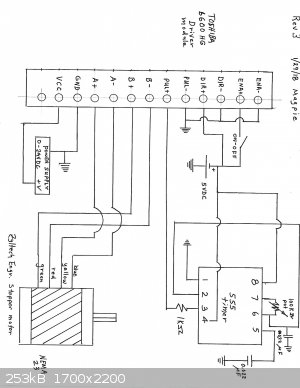
Attached is rev 3 of my wiring diagram. I think you will find it readable. The terminations for the 555 timer are an amalgam of direction you have
given and successful connections I have used in the past for a stepper motor. Please give corrections if you think it is inappropriate.
I don't plan to power up until you have approved the diagram.
Don
The single most important condition for a successful synthesis is good mixing - Nicodem
|
|
|
wg48
National Hazard
Posts: 821
Registered: 21-11-2015
Member Is Offline
Mood: No Mood
|
|
The connections to the module appear correct except for that you have a 1k in series with only one input signal. Its improbable that the inputs to the
module do not have identical characteristics so you need series resistors on all three or none at all.
I assume you have been unable to determine if the 1ks are needed or not. Perhaps if you examine the board inside the module you may be able to see
resistors on the board near the inputs and confirm their connection to the inputs with your ohm meter. (see the last diagram I posted.) If there are
no such resistors its probable that no resistor is needed on any of the inputs, if the 555 is operating on a 5v supply. More importantly it may not
work with 1k.
Hopefully you have performed the tests I suggested on the inputs in the absence of other information.
My suggestions for drawing the diagram were not so much to help my reading it but to help you not make mistakes like connecting motors inputs to
module inputs.
|
|
|
Twospoons
International Hazard
Posts: 1282
Registered: 26-7-2004
Location: Middle Earth
Member Is Offline
Mood: A trace of hope...
|
|
Every time you redraw the 555 timer it seems to be different - and not quite right.
Refer to this: https://www.electronics-tutorials.ws/waveforms/555_oscillato...
Helicopter: "helico" -> spiral, "pter" -> with wings
|
|
|
wg48
National Hazard
Posts: 821
Registered: 21-11-2015
Member Is Offline
Mood: No Mood
|
|
| Quote: Originally posted by wg48 | The connections to the module appear correct except for that you have a 1k in series with only one input signal. Its improbable that the inputs to the
module do not have identical characteristics so you need series resistors on all three or none at all.
I assume you have been unable to determine if the 1ks are needed or not. Perhaps if you examine the board inside the module you may be able to see
resistors on the board near the inputs and confirm their connection to the inputs with your ohm meter. (see the last diagram I posted.) If there are
no such resistors its probable that no resistor is needed on any of the inputs, if the 555 is operating on a 5v supply. More importantly it may not
work with 1k.
Hopefully you have performed the tests I suggested on the inputs in the absence of other information.
My suggestions for drawing the diagram were not so much to help my reading it but to help you not make mistakes like connecting motors inputs to
module inputs.
|
Oops!!! The comments about the resistors should read:
if there are no resistors on the board then series resistors will be required in the signals lines.
|
|
|
Magpie
lab constructor
Posts: 5939
Registered: 1-11-2003
Location: USA
Member Is Offline
Mood: Chemistry: the subtle science.
|
|
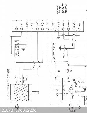
Here is Rev 4 for your review and comments. I popped the hood on the module and saw no resistors. I added R1 (1KΩ) so now each input has a
resistor.
Thanks, twospoons, for the link to the astable oscillator diagram. I incorporated this in Rev 4.
I should mention that diddi and varmint contributed greatly to my first stepper motor wiring diagrams for an overhead mixer.
Please review and comment.
The single most important condition for a successful synthesis is good mixing - Nicodem
|
|
|
wg48
National Hazard
Posts: 821
Registered: 21-11-2015
Member Is Offline
Mood: No Mood
|
|
No you have not added a resistor to each signal input and the resistor you did add appears shorted out !!!
The following is a corrected diagram. The red squiggles are resistors. I removed the incorrect connection between pins 4 and 7 and your R1.
I do not know if 1ks are the correct value to drive your module with sufficent current.
I have not checked the rest of the 555 circuit as it was not visible on your diagram.
PS you will have to add a switch to disconnect the battery or the battery will go flat when not in use.
[Edited on 31-1-2018 by wg48]
|
|
|
Twospoons
International Hazard
Posts: 1282
Registered: 26-7-2004
Location: Middle Earth
Member Is Offline
Mood: A trace of hope...
|
|
Once again the 555 diagram is not quite right. You are showing a direct connection from pin 4 to pin 7 - remove it or you will blow the chip, as pin 4
is also connected to the + supply! I strongly recommend you copy the diagram from the link I sent you verbatim. Chips do not have to be drawn with
the pin order as it is on the physical device - and in fact are seldom drawn this way as it makes the schematic messy and hard to follow. Connections
are never drawn inside chips. Clear and well laid out diagrams are essential in electronic engineering, for clarity of thought and ease of conveying
information.
Helicopter: "helico" -> spiral, "pter" -> with wings
|
|
|
Magpie
lab constructor
Posts: 5939
Registered: 1-11-2003
Location: USA
Member Is Offline
Mood: Chemistry: the subtle science.
|
|
Please review and comment on Rev 5, attached. Also please suggest values for C1, R1, R3, R4, and R5.
Please excuse the poor picture quality. My new printer/scanner just went tits up. So I had to do it the old fashion way: take a picture.
Many thanks,
Don
The single most important condition for a successful synthesis is good mixing - Nicodem
|
|
|
Twospoons
International Hazard
Posts: 1282
Registered: 26-7-2004
Location: Middle Earth
Member Is Offline
Mood: A trace of hope...
|
|
That looks perfect. Now you just need to work out appropriate component values. For the series resistors connected to the driver I think you would
be looking at values anywhere from 270 ohms to 1000 ohms. You'll just have to see what works.
Helicopter: "helico" -> spiral, "pter" -> with wings
|
|
|
Magpie
lab constructor
Posts: 5939
Registered: 1-11-2003
Location: USA
Member Is Offline
Mood: Chemistry: the subtle science.
|
|
Thanks, Twospoons. I will wait for wg48 to comment tomorrow morning before powering it up. He will likely have suggestions for the values.
I finally heard from Zyltech. All they did was refer me to somebody's YouTube video. I really doubt if they have anybody competent to deal with
on-line questions. OrientalMotor is much better.
Here's a list of components I have on hand:
resistors
4ea 1KΩ
5ea 220Ω
2ea 680Ω
capacitors
1ea 0.022µF
1ea 0.22µF
1ea 10 µF
[Edited on 1-2-2018 by Magpie]
[Edited on 1-2-2018 by Magpie]
[Edited on 1-2-2018 by Magpie]
The single most important condition for a successful synthesis is good mixing - Nicodem
|
|
|
Twospoons
International Hazard
Posts: 1282
Registered: 26-7-2004
Location: Middle Earth
Member Is Offline
Mood: A trace of hope...
|
|
Things like this are very useful to have.
That way you can pick and choose values on the fly, without having to special order every part.
I have assorted bags of both resistors and capacitors, in both leaded and surface mount varieties.
Zyltech probably know very little about the driver, beyond what is in the datasheet for the driver chip. I'd bet good money they buy in bulk from
china somewhere and slap their own label on it. If you want detail, read the TB6600HG datasheet.
[Edited on 1-2-2018 by Twospoons]
[Edited on 1-2-2018 by Twospoons]
Helicopter: "helico" -> spiral, "pter" -> with wings
|
|
|
wg48
National Hazard
Posts: 821
Registered: 21-11-2015
Member Is Offline
Mood: No Mood
|
|
| Quote: Originally posted by Magpie | Thanks, Twospoons. I will wait for wg48 to comment tomorrow morning before powering it up. He will likely have suggestions for the values.
I finally heard from Zyltech. All they did was refer me to somebody's YouTube video. I really doubt if they have anybody competent to deal with
on-line questions. OrientalMotor is much better.
Here's a list of components I have on hand:
resistors
4ea 1KΩ
5ea 220KΩ
2ea 680KΩ
capacitors
1ea 0.022µF
1ea 0.22µF
1ea 10 µF
[Edited on 1-2-2018 by Magpie]
[Edited on 1-2-2018 by Magpie] |
The two switches “power on” and “enable” may not be needed (just the power on may work fine) but it will work as shown so Ok great you seen to
have the connections correct now.
The required output frequency of the 555 is determined by the mode you select on the dip switches on the 6600 module (from memory) and the minimum
and maximum rmp required of the motor and the number of poles of the motor. The minimum pulse width and its polarity is determine by the minimum
pulse width requirements of the 6600 and which edge or pulse polarity. is required.. I do not know many of those parameters so I cannot review them.
I suggest you try the ones you have already selected at least to start with.
Best of luck with your first power up
PS;
[Edited on 1-2-2018 by wg48]
|
|
|
Magpie
lab constructor
Posts: 5939
Registered: 1-11-2003
Location: USA
Member Is Offline
Mood: Chemistry: the subtle science.
|
|
The values selected for R1, R3, R4, R5, C1, and C2 are 1KΩ, 680Ω, 680Ω, 680Ω, 0.22 µF, and 0.01µF, respectively. The lantern battery is 6vdc.
The VCC from the power supply is 12vdc. The circuit did not work.
I rechecked all terminations. I changed out the two capacitors and the 555 chip. Dip switches on the module are set "as received," ie, all up except
the 2nd one over from the left. The knife switches were bypassed.
If you have any suggestions to correct this please let me know.
The single most important condition for a successful synthesis is good mixing - Nicodem
|
|
|
Twospoons
International Hazard
Posts: 1282
Registered: 26-7-2004
Location: Middle Earth
Member Is Offline
Mood: A trace of hope...
|
|
what sort of test gear do you have? Do you have a meter that reads frequency? If not you could check the 555 output (pin3)by measuring AC volts - you
should get 3-6V if it is putting out pulses.
https://www.allaboutcircuits.com/tools/555-timer-astable-cir... suggests a frequency of 2kHz to 6kHz with your values - which seems reasonable.
Also is the rotor locked on the motor? Can you move it by hand with power applied? If you can move it then the driver is not enabled.
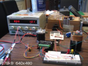
can you post a pic of your construction?
[Edited on 2-2-2018 by Twospoons]
Helicopter: "helico" -> spiral, "pter" -> with wings
|
|
|
Magpie
lab constructor
Posts: 5939
Registered: 1-11-2003
Location: USA
Member Is Offline
Mood: Chemistry: the subtle science.
|
|
I have a volt-ohm meter but no method for measuring frequency.
There is no voltage at 3 on the 555 chip.
I can turn the rotor by hand.
edit1: I am setting up a stand alone 555 astable pulse generator. This should help me troubleshoot why my stepper circuit is not generating a pulse.
edit2: Iam getting a voltage at pin 3 as detected with an LED. But, of course I can't detect frequency. But I do have switching diodes that I
verified the operation of a 555 once. Would that give frequency?
[Edited on 2-2-2018 by Magpie]
[Edited on 2-2-2018 by Magpie]
The single most important condition for a successful synthesis is good mixing - Nicodem
|
|
|
violet sin
International Hazard
Posts: 1475
Registered: 2-9-2012
Location: Daydreaming of uraninite...
Member Is Offline
Mood: Good
|
|
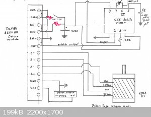
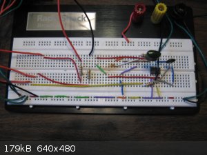
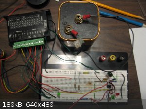
Top hot rail to field? A38 --> 5V or A35 --> 5V , I would have thought perhaps.
555Pin 3 should be a straight shot to pul+ controller (6th from right in picture) but it ties into what looks like ground (seeing as how
555Pin 1 is connected) as well as 555Pin 5 via ceramic cap right on breadboard.
[Edited on 2-2-2018 by violet sin]
|
|
|
Twospoons
International Hazard
Posts: 1282
Registered: 26-7-2004
Location: Middle Earth
Member Is Offline
Mood: A trace of hope...
|
|
Looks like you have pin 3 connected to ground (yellow wire) and to the end of the cap on pin 5 (grey wire). There's a real possibility your 555 is
dead as a result.
Also I can't see where +6V is connected to pins 8/4 - there appears to be no link to +6V.
Your driver clearly isn't running either because the rotor is not locked and there is no current draw on the ammeter of the power supply.
With every breadboard I've encountered the side rails are continuous along the whole length, and there is no need for all the little jumpers. Yours
may be the oddball, of course. Easy to check with a meter.
[Edited on 2-2-2018 by Twospoons]
Helicopter: "helico" -> spiral, "pter" -> with wings
|
|
|
Magpie
lab constructor
Posts: 5939
Registered: 1-11-2003
Location: USA
Member Is Offline
Mood: Chemistry: the subtle science.
|
|
I have completely rewired for clarity. I have replaced the 555. The 6vdc rail is the top most rail. The next one down is the ground rail. It is
continued at the bottom of the breadboard.
The pulse generator is still not running and the rotor is free.
my stand alone pulse generator was working as evidenced by an LED. Now, for some weird reason it has stopped working. I am going to continue to
troubleshoot this.
One problem I have is that the local Radioshack closed. I would like to buy some LEDs in case I blew the one that was working.
I will post pictures as soon as my camera battery is charged.
The single most important condition for a successful synthesis is good mixing - Nicodem
|
|
|
Magpie
lab constructor
Posts: 5939
Registered: 1-11-2003
Location: USA
Member Is Offline
Mood: Chemistry: the subtle science.
|
|
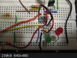
Here's the photos:
The single most important condition for a successful synthesis is good mixing - Nicodem
|
|
|
violet sin
International Hazard
Posts: 1475
Registered: 2-9-2012
Location: Daydreaming of uraninite...
Member Is Offline
Mood: Good
|
|
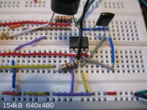
Hot 6v rail comes in on brown to meet with yellow ( --> pin 8) and the resistor. But also on pin 8 is brown --> green --> green -->
ground... Aka it goes 6v to ground.
|
|
|
| Pages:
1
..
4
5
6
7
8
9 |


