| Pages:
1
..
24
25
26
27
28
..
48 |
watson.fawkes
International Hazard

Posts: 2793
Registered: 16-8-2008
Member Is Offline
Mood: No Mood
|
|
Bismuth source
Apropos of a prior topic in this thread, I found, in another thread on this board, an online source for bulk bismuth (mooted for heater casting). http://www.rotometals.com/Bismuth-s/4.htm
EDIT: Looking around more, they carry the Bi-Sn eutectic alloy, melting point 281 F. No lead means less toxic, and in the right range for Teflon
insulation. http://www.rotometals.com/product-p/lowmeltingpoint281alloy....
[Edited on 25-3-2009 by watson.fawkes]
|
|
|
Swede
Hazard to Others
Posts: 491
Registered: 4-9-2008
Member Is Offline
Mood: No Mood
|
|
Good find, WF. But for me, at least, Bismuth AS AN ADDITIVE to a LD bath failed badly. But for use in another process, or a different angle towards
anode use, Bi could end up being very useful. The Bi salts I've looked at tend to be quite expensive with the sole exception of Bi subnitrate from a
pottery store.
With metallic Bi, it opens it up wide to preparation of the salt of interest from the Bi metal itself.
|
|
|
Rosco Bodine
Banned
Posts: 6370
Registered: 29-9-2004
Member Is Offline
Mood: analytical
|
|
Hmmm...about a year ago I posted this about a complexing of bismuth as a strategy for producing bismuth in soluble form in a less acidic medium, and
there were several other strategies which have been described also.
http://www.sciencemadness.org/talk/viewthread.php?tid=9783&a...
I have a bit more on this, possibly from an ancient reference Take unto thee of
bismuth nitrate two loth and of mannite five, and triturate together well in an agate mortar whilst murmuring the appropriate incantations prior Take unto thee of
bismuth nitrate two loth and of mannite five, and triturate together well in an agate mortar whilst murmuring the appropriate incantations prior
to dilution with a hundred loth of twice blessed rainwater,
and if not mannite then sorbitol or glycerol shall suffice but
the loth equivalency / conversion function key on my scientific calculator is worn out, so more now I cannot tell 
One part bismuth nitrate plus three parts glycerin reportedly forms a water soluble compound also.
Soluble complexes have also been mentioned, glycine, EDTA,
and nitrilotriacetic acid are operable.
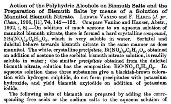

http://sciencemadness.org/scipics/Bismuth%20nitrate%20compou... direct view link for pdf , download save link below
Attachment: Bismuth nitrate compound with Mannitol.pdf (102kB)
This file has been downloaded 772 times
[Edited on 27-3-2009 by Rosco Bodine]
|
|
|
tentacles
Hazard to Others
Posts: 191
Registered: 11-11-2007
Member Is Offline
Mood: No Mood
|
|
It's a bit off topic, I suppose, but I slapped together my spot welder today. It's like a ghetto version of Swede's unit. I *do* have a timer relay to
use with it, but it didn't come with a relay base so I gotta dig one up, and need a SSR to switch the transformer. I blew the crap out of the 15A fuse
in the background of the picture... Plugged it into my stove outlet since I knew it was going to gulp down power. The 15A fuse lasted a good 12-15
spot welds, it actually blew when unplugging the welder, not during the use. Clearly I need to get that SSR et al. Or at least a light switch!
The nylon handle on the threaded rod holding the top electrode to the destaco clamp is for free-handing it. The bottom electrode just sits in the
holes in that copper bar, so I can move it out and use the handle for stuff that won't fit in. A bigger Destaco clamp is in my future, and a longer
bar so I don't have to freehand.
The windings only got a little warm after welding all those anodes - about 28 welds. The bus bar and electrodes got quite warm.
http://pyrobin.com/files/sdc10009.jpg
[Edited on 30-3-2009 by tentacles]
|
|
|
dann2
International Hazard
Posts: 1523
Registered: 31-1-2007
Member Is Offline
Mood: No Mood
|
|
Hello,
@ Tentacles
I think you should refer to the device as the PMSW* 
Looks good. I must put one together myself. I have a large AC welder and it would be fairly easy to make up electrodes and a clamp.
One thing about Microwave transformers (AFAIK) it that they will pull a very high current from the supply when there is no load on the secondary
winding. The reason for this is that the microwave transformer is designed as skimpy as possible and the designer knew that there would ALWAYS be a
load connected to the output winding (the Magnetron). This allows them to only put about half the more usual amount of windings on the primary and get
away with it. When you go to use the transformer (either with a new output winding or even the transformer as it came out of the oven for some High
Voltage application) and you do not put a load on the output (when you are not actually welding in your case) you will get a very high current going
into the primary, much higher than a 'properly' designed transformer.
A good way to counteract this is to use two transformers with the primarys in series and you can put whatever you wish on the (in your case rewound)
secondaries.
This heavy current may not be helping the fuze. Can you measure the input current when you are not welding with perhaps a clamp meter?
Hope I am right on the above.
Cheers,
Dann2
*Poor Mans Spot Welder
|
|
|
watson.fawkes
International Hazard
Posts: 2793
Registered: 16-8-2008
Member Is Offline
Mood: No Mood
|
|
Quote: Originally posted by tentacles  |
[I] need a SSR to switch the transformer. I blew the crap out of the 15A fuse in the background of the picture. [...] The windings only got a little
warm after welding all those anodes - about 28 welds. The bus bar and electrodes got quite warm. |
The fuse
blew because of inductive kick. There's energy stored in the magnetic field of the transformer primary—quite a lot of it, actually. It's
only stored there as long as current is flowing. Turn off the power, and the voltage spikes. (This is how the coil for a spark plug works.) So when
you pulled the plug, you dumped that energy back into the mains. By happenstance, the neutral disconnected first, so the voltage appeared across the
circuit breaker.
You can also use a motor contactor to switch the mains current. A contactor is just a big relay, but one specially made for switching inductive loads,
such as (in this case) an open-loop transformer. The issue is inductive kick. The contact of a contactor are designed to handle the spark that's
generated from a sudden disconnection without failing quickly.
The head at the electrodes and bus bar is hardly surprising. Spot welding is a welding process, and things near the weld get hot. The fact that your
windings were only a little warm means that you're using your welder well within its safe operating envelope.
|
|
|
watson.fawkes
International Hazard
Posts: 2793
Registered: 16-8-2008
Member Is Offline
Mood: No Mood
|
|
| Quote: Originally posted by dann2 | I must put one together myself. I have a large AC welder and it would be fairly easy to make up electrodes and a clamp. [...]
One thing about Microwave transformers (AFAIK) it that they will pull a very high current from the supply when there is no load on the secondary
winding.[...]
This heavy current may not be helping the fuze. Can you measure the input current when you are not welding with perhaps a clamp meter?
|
Commercial resistance welding equipment (which includes spot welders) generally uses separable power supply
and electrode/clamp systems. I can recommend this approach heartily, since there are a number of clamping geometries that come in handy. As a common
example, spot welding cells into battery packs use an electrode pair with both electrodes facing down.
The shunts in an MOT do change the current flow, but you can simply remove them, which is particularly easy if you're rewinding the secondary. A quick
search turned up this page: http://wiki.4hv.org/index.php/Microwave_oven_transformer
As far as quiescent current flow, it's drawing less than the fuse rating, or it wouldn't have lasted even one or two welds. A typical MOT is in the
1-2 kW range, simply because that's the rating of the oven, and the oven must be able to work on a 15A circuit. It's the inductive kick that blew out
the fuse. Cartridge fuses work with inductive loads because they blow only with sustained current flow.
|
|
|
Swede
Hazard to Others
Posts: 491
Registered: 4-9-2008
Member Is Offline
Mood: No Mood
|
|
Looks good to me! Your transformer has gobs of beef. If you can find a foot switch that can handle the primary current, that would perhaps be an
easy way to control it a bit, although the inductive kick-back, I'm not sure where that energy would go!
If you do end up looking for a timer, just find the cheapest, easily adjustable "one-shot" timer you can find, at least one that allows sub 1-second
welding, and perhaps adjustable by tenths of a second, plus a matching SSR with an AC control terminal set. It's odd, I never really thought about
the inductive thing when the primary is turned off, and given that, would have expected a short life for the SSR, but it's soldiered on for years now.
I've used mine anywhere between 0.1 S to maybe 3S max. The 0.1S welds were cool, it was like a sewing machine stitching up thin sheet SS. Mine is
too light to do carbon steel, but it does Ti and SS like crazy. Still heats too much, though.
It looks like it did the job on those anodes. Did you find you had to scrape the MMO coating off the eBay material for the weld to be secure?
The only other issue is the geometry of the Cu electrodes, and it looks like you got those knocked as well. Nice work.
[Edited on 31-3-2009 by Swede]
|
|
|
Swede
Hazard to Others
Posts: 491
Registered: 4-9-2008
Member Is Offline
Mood: No Mood
|
|
We had discussed pH control in some detail in this thread, and I am convinced that it can be done very well, if your cell has sufficient volume (4L or
better) using TIMED dosages of HCl. I found that 1 minute ON, 59 minutes OFF, of a Hanna dosage pump, was perfect.
The trick isn't the dosing pump, which can be expensive; the trick is in the timer. Every timer I found locally and OTC had major drawbacks, such as
coarse controls and a tricky interface. Industrial timers and controls are expensive. Then I found this one, a real steal at $32.
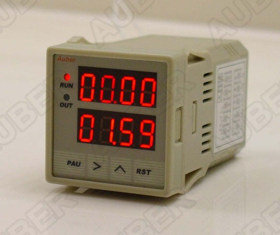
http://auberins.com/index.php?main_page=product_info&cPa...
I received it today, ran a few tests, and found it to be perfect, giving me control to the minute or less. This means I can set my dosing pump on a
schedule that will make the system more stable. It has an internal relay that can drive the dosing pump, but I am going to use the mechanical relay
to power a SSR instead, to prolong the life of the mechanical relay contacts, which does not look serviceable.
Hope this helps someone. The same relay can control a solenoid valve or just about any device imagineable to administer HCl to a cell.
[Edited on 31-3-2009 by Swede]
|
|
|
watson.fawkes
International Hazard
Posts: 2793
Registered: 16-8-2008
Member Is Offline
Mood: No Mood
|
|
| Quote: Originally posted by Swede | If you can find a foot switch that can handle the primary current, that would perhaps be an easy way to control it a bit, although the inductive
kick-back, I'm not sure where that energy would go!
[...]
It's odd, I never really thought about the inductive thing when the primary is turned off, and given that, would have expected a short life for the
SSR, but it's soldiered on for years now. |
As for a foot switch, it can switch a contactor relay or SSR just
fine. If you run mains current through it, that's where the inductive kick goes; in such a case expect the switch lifetime to be low.
Inductive kick consists of energy that dissipates somewhere, either in a spark or in heat dumped into some circuit element. A typical solid state
protection circuit is a pair of a back-to-back zener diodes. One of the zener diodes breaks down under the kick and provides a low-resistance path.
Such protection diodes are fairly large so that they can dissipate the heat without permanent damage. It's likely your SSR has a pair built in to the
output.
|
|
|
Swede
Hazard to Others
Posts: 491
Registered: 4-9-2008
Member Is Offline
Mood: No Mood
|
|
Ahh, that makes sense. I would have expected some sort of protection for the SSR. Unfortunately, one of the failure modes (actually the most likely
one) is the SSR blown to the ON, high current, mode. Still, I am sold on the ease of use and economy of SSR's. They are handy beasts. Even if your
circuit is only going to draw, say, 5 amps, I think it is a good idea to provide a bit of overkill in the SSR, and fuse it to boot. A 40 amp job
costs not much more than a 10 amp.
For those unaware - you only get the rated amperage when the SSR is properly heat-sinked, and the heat sink can cost more than the SSR. But if your
duty cycle is low, and the SSR large enough, you can run it "naked" with little problem.
I am going to treat this timer like my temp. controller - box it nicely and turn it into a useful, and long-lived, piece of lab equipment.
|
|
|
Gamal
Harmless
Posts: 24
Registered: 6-11-2005
Location: Sweden
Member Is Offline
Mood: No Mood
|
|
Homemade dosage pump
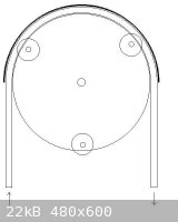
I've been thinking about an easy way of building my own dosage pump. The ground idea is shown in the pic below.
It's a center wheel with three or four smaller wheels, maybee spring loaded, pushing a hose against an outer rail. When the center wheel turns the
liquid in the hose is squeezed thru the hose in the rotation direction.
The weel could be turned by a low gered electric motor like a servo. The motor can be controlled by a timer like Swede's.
If you know the inner area of the hose and the turning speed of the motor, it's easy to calculate the time and interval for a specific amount of
liquid to be trasported.
The construction should be quite simple. My biggest problem is to get a well working hose. It has to be very flexible and withstand HCl. I think
silicone should work, but I haven't been able to test it. Does anyone have a suggestion.
[Edited on 1-4-2009 by Gamal]
|
|
|
dann2
International Hazard
Posts: 1523
Registered: 31-1-2007
Member Is Offline
Mood: No Mood
|
|
Hello,
@Gamel. You are building a peristaltic pump. I think most of the flexible tubing that are suitable for these types of pumps will withstand HCl. The
12% stuff is easy to handly in just about any plastic. Neoprene and Marprene (trade mark of Watson Marlow (pump makers)) I have seen used with acids.
If you look over in the "Reagents and Apparartaus" thread there is a thread on Waterpumps.
One very interesting type of homemade/field expedient pump is to use an aquarium pump for pumping air. I will quote from the original guy (Unionised)
who suggested it:
______________________________
I'm not sure how well it would work in this instance but there is a pump with no wetted moving parts to corrode.
If you put tube in a bucket of water (HCl in our case(dann2)) and pump air down a thin pipe, the end of which is under the end of first pipe, so it
forms bubbles. In the pipe you get a column of mixed air and water, this isn't as dense as water so it rises. A mixture of bubbles and water comes out
of the pipe and, if you have it run into a header tank you can let it run down through the scrubber and back to the bucket.
Not a very efficient pump, but relatively robust, you just need an fish tank aerator to run it and those run for years.
_________________________________
This would work fine for dosing HCl into a cell. Just put the air pump on a timer.
Dann2
|
|
|
Gamal
Harmless
Posts: 24
Registered: 6-11-2005
Location: Sweden
Member Is Offline
Mood: No Mood
|
|
Thank's dann2! It's allways nice to know what you are trying to build
I like the peristaltic type (allmost invented it ). It looks like they use teflon
or silikone hoses most.
I'm sure I'll use it with uther chemicals, so I think teflon is the best choise then.
What do you think about using a needle bearing with some of the needles removed and some type of clamp over it. It would make a very simple
construction I think.
|
|
|
Swede
Hazard to Others
Posts: 491
Registered: 4-9-2008
Member Is Offline
Mood: No Mood
|
|
Gamal, I don't want to discourage ANY DIY project, but be aware that you can pick up used peristaltic pumps for next to nothing off eBay. The work
involved in making one from scratch would not be trivial! 
If you want to see what's out there, search for peristaltic pumps or "Masterflex" which is a series of pumps and heads offered by Cole-Palmer. As for
tubing, there are dozens of formulations and sizes, many of which will do HCl with ease, but PTFE is a different beast. Besides being expensive, PTFE
tubing has little elasticity and has a limited lifetime and efficiency in a peristaltic head.
Here is a page with technical resources, including tubing compatibility:
http://www.grayledge.com/MasterflexBarnantIPPumps.html
Another plastics vs. chemical compatibility guide:
http://www.innocalsolutions.com/TechInfo/ChemComp.asp
Tygon is a good choice. Yet another tubing URL:
http://uscorp.thomasnet.com/category/tubing-hose-saint-gobai...
We also tend to forget about good old gravity as a means to deliver. Given some head pressure from a vessel higher up, all you need to do is turn a
suitable solenoid valve on and off.
[Edited on 2-4-2009 by Swede]
|
|
|
dann2
International Hazard
Posts: 1523
Registered: 31-1-2007
Member Is Offline
Mood: No Mood
|
|
Hello Folks,
I will second what Swede has said but pumps are a bit more scarse in Europe if you are in that direction.
There is nothing to beat the BikeMaster acid addition method. The solonoid would be great too.
About the pump above that I suggested (using an aquarium air pump). This would be a great cheap pump for plating Lead Dioxide if the maker was going
to have two tanks. The pump is cheap but all that air going through a long columb of the plating liquid would help keep any Nitrites formed (bad)
oxidized to Nitrates.
@Swede
About the .doc on LD plating. I was thinking you should mention in relation to tank size what size you should use based on the fact that X amount of
Nitric Acid is produced per Y amount of LD plated.
Say you are going to plate 100grams of LD onto an anode (LD has a density of 9.2 grams per CC (I think)) than in order to not have Nitric acid
concentration go above (say) 20 grams per liter (or whatever you think is an absolute upper maximum that is tolerable) you will need a minimum tank
size of Z liters. This is all assuming that the maker is not adding Lead Compounds during plating to get rid of acid/keep Lead Ion concentration high.
Dann2
|
|
|
Swede
Hazard to Others
Posts: 491
Registered: 4-9-2008
Member Is Offline
Mood: No Mood
|
|
@dann2 - very good point on the LD info. I need to do more research on the evolution of nitric as a function of coulombs, and also the mass of LD
with the same parameter in mind. I also need to attempt to portray some of the chemistry as a balanced equation.
The deluxe timer is finished. Remember, this unit is designed to control HCl addition via a dosing pump, down to the second.
I found the ideal box for this sort of project - rather than use electronics enclusures, I simply used an outdoor PVC junction box from a hardware
store.
The lid of the box was slotted, cut, and drilled for the essentials - an outlet, switch, 115VAC neon light, and ov course the timer itself:

Then, I populated the lid and began to wire it appropriately, using mostly crimp terminals.

The finished project - It came out nice, and should satisfy any lab needs for a precision timer.

In use, the switch powers on the timer, and enables the system. When the timer activates the SSR, the neon light illuminates, and of course power is
delivered to the outlets.
One oddity that I overlooked... an SSR has a minute leakage across the output terminals, and having nowhere to go, the hot receptacle gets charged to
120VAC. I remembered this in the initial tests, when I put a DVM across the outlet with the power off, and to my dismay, found 120V there. But if
you plug something in, it does not work. Only when the SSR is properly switched ON via the timer does the attached appliance (in the test, a portable
radio) turn on.
It probably doesn't hurt anything, but it bugs me. Perhaps a resistance to pull the leakage to ground would eliminate it. I'd guess the current
would be microamps. Any thoughts?
[Edited on 2-4-2009 by Swede]
|
|
|
dann2
International Hazard
Posts: 1523
Registered: 31-1-2007
Member Is Offline
Mood: No Mood
|
|
Nice job.
I would imagine a 20K resistor accross the output would stop the 'charging' when the timer is off. This would draw about 6 milli amps when power was
on and short the leakage/'charging' current when power is off.
Is the 'charging' current (when timer is off) an AC? Don't know much about SSR's myself.
A balanced equation for LD plating is:
Pb(NO3)2 + 2H2O =====>> PbO2 + 2HNO3 + H2
Density of Pb02 is 9.37 grams/cm^3.
I thing that the first thing to cause a bath to 'go bad' is the build up of Nitric acid as opposed to either the depletion of Lead Ion (so long as you
started with a sensible concentration of Lead Ion) or build up of Nitrites.
My LD Anode cell that I am running with pH contoll has started to produce Perchlorate today. It has been running for 23 days. This CE is somewhat less
(guesstamation of 70%) than the Graphite Anode cell with pH controll. Perchlorate appeared in both cells after 23 days (coincidence) but the LD Anode
cell has greater current going into it so assuming that both have started to make Perk. at the same Chloride concentration (this may not be the case)
then CE of LD Anode cell is going to be ~15% less than the Graphite cell during the Chlorate stage of the cell (Graphite cell was ended at this point
BTW).
There is very little erosion of the LD in this cell unlike the last cells I ran with the LD Anode with no pH controll. There is very little Lead
depositing on the Cathodes. pH controll seem to be the Oil that runs Chlorate cells. More CE, less erosion more joy (more cost though).
We shall see ever the next few days how it goes at the Perchlorate stage of the cell.
I am still adding acid to the cell. It still seems to need it as the pH is not going way down (like the Graphite Anode cell) but staying at approx. pH
7 with the acid still going in. Acid addition was small over most of the run compared to Graphite Anode cell. I am taking samples every three days
approx. and I will titrate and see what is/was happening when cell is finished (finished being low Chlorate concentration of a few grams per liter).
@Gamal
I enjoy stating the obvious!!
What is a needle bearing? Are you trying to make a peristaltic pump from one.
Dann2
[Edited on 2-4-2009 by dann2]
|
|
|
Swede
Hazard to Others
Posts: 491
Registered: 4-9-2008
Member Is Offline
Mood: No Mood
|
|
| Quote: |
A balanced equation for LD plating is:
Pb(NO3)2 + 2H2O =====>> PbO2 + 2HNO3 + H2
Density of Pb02 is 9.37 grams/cm^3.
I thing that the first thing to cause a bath to 'go bad' is the build up of Nitric acid as opposed to either the depletion of Lead Ion (so long as you
started with a sensible concentration of Lead Ion) or build up of Nitrites.
|
Given that my LD Anode #2 gained almost 150 grams of mass, and assuming it's all LD, then it took up 0.672 moles of LD, and generated 1.344 moles
nitric, or 84 grams. This is intersting when you consider the starting concentration of HNO3 in my big cell was 5 grams per liter, or about 25 to 30
grams total. So the Nitric would have tripled in concentration without control of its evolution. From my reading, 20 grams per liter was considered
the absolute upper limit for successful plating, and I think a good goal would be keeping it below 10 grams per liter. If I had done nothing to
control evolved nitric during the plating process, the concentration would have risen to 20 grams per liter, or slightly higher, in a 6 liter bath.
Not many guys attempt a bath that size. If the bath was 2 liters instead of 6, the concentration of nitric, to create the same mass anode (150
grams), would result in a 2 liter bath containing 94 grams HNO3; 47 grams per liter, well above what the published sources would allow. Perhaps that
is what is killing LD attempts at home - small baths, plus soaring acid content = less than optimum anodes.
Thus, I think your conclusion is sound. At 375 grams per liter lead nitrate to start, there are plenty of lead ions available even in a 2 liter bath,
but the nitric acid produced wrecks the plate job before it's complete, unless litharge or lead hydroxide is added in controlled dosages and with good
frequency.
Further, unless you have an automated setup, I'd be leery of running a plating job overnight, unattended.
Good job on the perc production. Is there a particular current density that a LD anode is most efficient at, and/or one which should not be exceeded
when running chlorate --> perchlorate?
[Edited on 2-4-2009 by Swede]
|
|
|
Gamal
Harmless
Posts: 24
Registered: 6-11-2005
Location: Sweden
Member Is Offline
Mood: No Mood
|
|
Dann2
I'm sorry, I'm swedish. It was a direct translation. At least you had some fun
It's like a ball bearing but with small rolls instead of balls.
If I can pick some of them out and clamp the hose between it and a rail of some type, I only have to turn the bearing to pump the fluid.
Thanks Swede for the links! I think I'll try PVC at first. However I have a feeling it will harden after some use.
|
|
|
Gamal
Harmless
Posts: 24
Registered: 6-11-2005
Location: Sweden
Member Is Offline
Mood: No Mood
|
|
Dann2
I've found the word for my "needle bearings". It's linear bearings
|
|
|
dann2
International Hazard
Posts: 1523
Registered: 31-1-2007
Member Is Offline
Mood: No Mood
|
|
Hello,
I would call the 'needle bearing' a roller bearing. Descriptions and names change from place to place.
You would need a very large roller bearing for the 'rollers' to be sensible size for making a Peristaltic pump.
If you are going to make a Peristaltic pump you will need a geared motor that turnes the output shaft fairly slow. The wiper motor of a car has a
suitable motor + gearbox. You could speed controll it too with an SCR chopper circuit or a variable voltage supply (say approx 5 to 13 volts DC) or
even a big wattage resistor.
PVC varies greatly in how stiff or rigid it is depending on how much plasticizer has been added to the melt as the tube is being made. Stiff tubing
in a Peristaltic pump will NOT work.
Try Googling 'Homemade Peristaltic pump'.
One showed up at this URL:
http://www.instructables.com/id/EUM86I9613EP28786D/
It's a woeful looking beast!
If you talk sweet to Panache he might send you a pump from Oz land!!!!!!!!
@Tentacles
What I was saying about the high magnetizing current going into your modified microwave oven transformer (and helping to blow the fuze) does not
apply if you are switching on the power when the welding clamps are already applied to the load (which I think you are doing).
Was not thinking too clearly when I was posting above............
Dann2
|
|
|
dann2
International Hazard
Posts: 1523
Registered: 31-1-2007
Member Is Offline
Mood: No Mood
|
|
Neutralizing with liquid from neutral tank
Hello,
@Swede
Your calculation is slightly out but not a big deal. You stated .672 moles LD instead of 0.627 (64 grams Nitric acid as opposed to 84 grams).
I have a question you's can think about. If you go to use a two tank system with a pump in between. One tank is plating (and will hopefully have
between 6 and 10 grams Nitric acid per liter from the pumping effort), and the other tank is neutral (an excess of neutralizing Lead compound in it
but not acutally suspended in the liquid as we want liquid only going into plating tank(use a filter or something)).
I calculate that at 100% plating CE you will get 2.35 grams Nitric acid forming per amp per hour.
How much of the neutral fluid do we need to pump so that the plating tank stays in the 6 to 10 grams per liter Nitric acid region.
It is easy enough to figure out how much solid compound to add to a plating tank. It's just a matter of keeping the moles happy but the liquid
addition stuff has me stumped (it may be the late night, the absolute Alcohol and pills etc )
See cut and paste below for some of my reasoning (rambllings). Your welcome to check my figures!
_____________________________________________
<b><i><u>The tank should have a reasonable
volume in relation to the amount of Lead Dioxide that you are going to plate in one sitting.</i></u> </b><br>
Nitric acid is formed as plating progresses. To stop the concentration of Nitric acid from becoming too high you must have a suitible large tank (if
using a one
tsnk system) or if using two tanks with a pump then the total plating solution volume need not be so large. You must add neutral solution to the
plating tank at
the appropriate rate.
<br><p>
It would appear from patents etc, that the best concentratioin of Nitric acid to have in your plating bath is in the region of 6 to 10 grams Nitric
Acid per liter. The
Nitric acid concentration will increase once you start to plate. You will get two moles of Nitric acid forming for every mole of Lead Dioxide that you
plate, (126
Grams acid for every 239.2 Grams Lead Dioxide, = 0.527 grams acid per gram Lead Dioxide deposited). Most amateur Anodes end up getting formed from
baths with much more that the ideal concentration of Nitric acid. If using a one tank system a large tank is necessary. If you start your plating
operation off with 6
grams per liter Nitric acid and you want to avoid the acid concentration going above 12 grams per liter Nitric acid you will need a tank size of
87.8ml per gram
Lead Dioxide that you want to deposit. <br>
Figure out how many grams of Lead Dioxide you need to deposit to form your Anode from the projected Anode dimensions minus the substrate volume
multiplied by the density of Lead Dioxide (9.37 grams per cc). <BR>
For example if you want to deposit 100 grams Lead Dioxide (not a large Anode) and you decide to start off your plating solution at 6 grams per liter
Nitric acid
and you do not wish for the acid concentration to go above 12 grams per liter, then you need a minimum (one tank system with no adding in of Lead
Compounds during plating) of 100 multiplied by 87.8 = 8.8 liters. That's a big tank!! It would appear that adding Lead Compound (with or without a
second tank)
is the sensible way to go if the acid concentration is to be kept in the most desirable range.<P>
The amount of Lead ion per gram of PbO<small>2</small> is 0.839 grams. The amount of Lead ion per gram of Lead Nitrate
(Pb(NO<SMALL>3</SMALL>
<SMALL>2</SMALL> is 0.6256 grams. Therefor each gram of
deposited Lead Dioxide will use up 1.341 grams Lead Nitrate. The concentration of Lead Nitrate should not be let fall below 200g/liter. If the tank
size is large
enough to keep the Nitric acid concentration at resonable levels then Lead Ion depletion of the plating solution will not be a problem. It is
advantageous to
have the Lead ion and Nitric acid concentration as constant as possible during plating.
When going for a one or two tank system and adding Lead Compound the total plating solution volume need not be as large as when using a one tank
system with no addition of Lead Compound. If using a two tank system the neutral tank will have an excess of neutralizing Lead Compound in it. The
pump will
slowly pump this neutral plating liquid into the plating tank at a rate that will keep the Nitric Acid concentration at approx 6 to 10 grams per liter
in the plating
tank. <BR> If using a one tank system and adding Lead compound you will need to add the amounts in the table below<p>
Each mole of Electrons (26.8 amper hours) that flows will produce one mole Nitric acid (63 grams), assuming 100% current efficiency, which is equal
to 2.35
grams Nitric acid forming per hour per amp.<br>
Another way to look at this is to say that a half mole of Lead Dioxide is plated onto the Anode per 26.8 amper hours, (119.6 grams Lead Dioxide
per 26.8
amper hours) which is equal to 4.463 grams Lead Dioxide per amp per hour. You need to add Lead Compound to replenish the transfered Lead Ions and
depending on the Lead Compound you are using the weight added will need to equal the molar amounts of Lead Ion being transfered. The table below gives
the relevent molecular weights of the Lead compounds that are used and thus the amounts to add to the tank per amp per hour.<p>
<TABLE border=2>
<TBODY>
<TR>
<TD>Compound</TD>
<TD>Grams of compound to add to tank<BR>per amp per hour @100% CE</TD>
<TR>
<TR>
<TD>Litharge (molecular weight = 223)</TD>
<TD> 4.16</TD></TR>
<TR>
<TD>Lead Carbonate (molecular weight = 267) </TD>
<TD>4.985</TD></TR>
<TR>
<TD>Basic Lead Carbonate (molecular weight = 775)</TD>
<TD>4.824</TD></TR>
<TR>
<TD>Lead Hydroxide (molecular weight = 241)</TD>
<TD>4.508</TD></TR></TBODY></TABLE><p>
Since CE will be less than 100% you will need to add less that the table above states.
<p><br>
When using a two tank system with Lead Dioxide deposition being performed in one tank and an excess of neutralizing Lead Compound in the other tank
(neutral plating solution), then you must pump neutral liquid into the plating tank at the appropriate rate. Since the Nitric acid concentration in
the neutral tank is
zero you need to pump this neutral solution at a rate of XXXXXXXXXXXXXXXXXXXXXXXXXXXXXXXXXx<p><br>
It may be possible to have an excess of Litharge at the bottom of a one tank system (if stirring is not used or perhaps intermittent stirring) which
will react fairly
slowly with the Nitric as it is produced and help keep the Lead ion concentration constant and the Nitric acid concentration in the wanted range. If
the Litharge
is too finely divided (small particle size) it may react too easily with the Nitric acid and be inclined to keep the pH of the bath too high
(concentration of the Nitric
acid will be too low). You cannot use Lead Carbonate or Hydroxide or Basic Lead Carbonate in excess in the one tank system as they will keep the pH
too
high (they react too readily with the Nitric acid formed) and the Carbonate will also cause bubbles/foaming as it reacts with the Nitric acid. You
would need
some way to add (by hand even) the compound into the tank as plating progresses. A slurry could also be pumped perhaps.<br><p>
____________________________________________
Regarding Perchlorate making with LD, a higher current density on an LD Anode actually increases CE in the Perchlorate cell. I am not too sure what
is the optimum CE. The cell is still needing acid to keep it at around pH of 7 which is different that the Graphite Anode cells. I don't know what the
Chloride conc. is, but there is lots of Perchlorate at this stage. Some Lead appearing on Cathodes. Taking samples etc. Will report.
Dann2
|
|
|
Swede
Hazard to Others
Posts: 491
Registered: 4-9-2008
Member Is Offline
Mood: No Mood
|
|
Dann2, those are all excellent thoughts. My original goal was to see if there was some simple way to create a one-pot LD plating system that was not
overly large. I STILL haven't tested anode #2, but my gut says "it will work." Maybe that's just wishful thinking. But comparing ugly anode 1 with
anode 2... anode 1 is shedding LD particles in its little ziploc bag and is a total disaster. Anode 2 is completely intact, apparently strong, and
has a velvety surface that looks like it will have a huge surface area. I want to finish the data collection setup first. But all that aside...
A two tank LD plating setup may be the way to go, but I am a bit leery about taking a system that is already a bit complex (My
Vibrating/rotating/stirring plating gantry) and adding additional plumbing. I keep thinking about the effort that went into my "T-Cell", the
two-chambered, pumped (per)chlorate system that failed spectacularly due to clogging. Then, I turned it into a big monolithic cell that produces 4.2
kg chlorate in 3 days; a case where KISS ruled.
Despite my best mechanical effort at plumbing the T-cell, there was still significant salt creep, and I am afraid that a two-tank LD system would be
leaching lead nitrate all over the place, a bit scary. Perhaps the way to go for LD is chambering a single cell, rather than plumbing/pumping between
two cells. Somehow, the nitric acid-rich plating environment would interact with the neutralization chamber, but how that could be accomplished with
a minimum of complexity, I don't know.
I do know that manually adding litharge during the plating of anode #2, with mild stirring into the corner of the 6 liter tank, and all based upon pH
measurements, seemed to work. It was crude, not very scientific, but could perhaps be more specific and perhaps automated.
The pH with a decent (but not great) probe varied between 0.0 and 0.5. When it dropped to zero (or negative) I added a teaspoon of litharge. Within
minutes, it was back to 0.5, then it would slowly begin its journey downward. The worst part was in the initial, high-amperage phase of plating... I
was adding litharge every 15 minutes or so. Once the amperage was dropped, additions likewise were reduced. I am afraid that a layer of litharge in
the plating tank would raise the pH too far, but as you say, if the litharge is in a neutralization chamber or tank, and the plating liquor was cycled
through at a slow rate, I think you'd get a stable pH and the likelihood of success would be high.
Lots to think about and chew on. It's too bad litharge is insoluble. It would be a simple matter if it could be dissolved and then dripped. How do
you slowly introduce a powder at a constant rate into a plating chamber? A powder trickler?
|
|
|
dann2
International Hazard
Posts: 1523
Registered: 31-1-2007
Member Is Offline
Mood: No Mood
|
|
Thanks for that. I was thinking about having two tanks and a peristaltic pump between them. No plumbing involved as such. But you would need a
Peristaltic pump!
How much to pump I will have to think about.
Your Anode will work no doubt. My Anode has close on 4 months clocked up and I would coinsider it still working. It has eroded though and CE was not
too hot.
Someone suggested an orger for the powder. Sounds simple enough IF you already have one or are willing to purchase one.
It is surprising how big the tank need to be if you are not adding compound and you want Nitric to stay low (within the high quality band).
Perhaps the one tank with a division made from a piece of cloth. Some diffusion will happen.
Dann2
|
|
|
| Pages:
1
..
24
25
26
27
28
..
48 |


