| Pages:
1
2 |
wish i had a kraken!!!
Hazard to Others

Posts: 157
Registered: 22-3-2012
Member Is Offline
Mood: No Mood
|
|
I NEED HELP (FOR MAKING HIGH POWER TRANSFORMESR!)
HELLO EVERYONE ,
HERE https://www.youtube.com/watch?v=52Oi95St_lY is a link of my homemade HighVoltage Power supply -I made it buy connecting 3 MOTs - , For some
reasons I need To make a HIGH POWER HIGH VOLTAGE POWER SUPPLY (Similar to so called bombarder transformers!) But I couldn't find the calculations
suitable for making transformers with powers more than 3.5 KiloWATT !
I need help of anyone who Knows the exact calculations nedded for making a transformer with POWER EQUALS TO 9 KILOWATT OR MORE.
Regards
Nima
[Edited on 19-12-2014 by wish i had a kraken!!!]
|
|
|
froot
Hazard to Others
Posts: 347
Registered: 23-10-2003
Location: South Africa
Member Is Offline
Mood: refluxed
|
|
A transformers power is dependent on it's magnetic core volume and operating frequency. If you can see a VA rating on a MOT all you do is divide the
required power by the VA rating to get the number MOT's you need. Transformers with normal laminated cores work fantastically at 200Hz and by doing so
you can get more than triple the rated power through them. The trick then would be to supply them with 9kW power at 200Hz. Best I can suggest for now
is using a variable frequency motor drive.
We salute the improvement of the human genome by honoring those who remove themselves from it.
Of necessity, this honor is generally bestowed posthumously. - www.darwinawards.com |
|
|
wish i had a kraken!!!
Hazard to Others
Posts: 157
Registered: 22-3-2012
Member Is Offline
Mood: No Mood
|
|
Thanks froot , But I don't want to use MOTs anymore , I want to wind up the Transformer that I need , and I need calculations for that , The area of
its core , The Number of turns for primary & secondaries and so on FOR MAKING A BOMBARDER NEON TRANSFORMER.
IN FACT I DON'T KNOW ANYTHING ABOUT WINDING A BOBARDER NEON TRANSFORMER (like the one in the picture or ones here http://www.sinolite-neon.com/ProductShow.asp?id=216)!
[Edited on 19-12-2014 by wish i had a kraken!!!]
.bmp - 755kB")
|
|
|
IrC
International Hazard
Posts: 2710
Registered: 7-3-2005
Location: Eureka
Member Is Offline
Mood: Discovering
|
|
As lacking in knowledge and understanding of the math and theory you appear to be from your own words I suggest you wait a few more years studying and
working on things much more safe than your wild dreams. First off you have not stated the voltage and current required. Second you should be talking
KVA not kilowatt. If you need an example of the size required I suggest you look at a 10 KVA pole pig up on a pole in your neighborhood. A pole or
plate transformer not an NST is what you are talking about at this power level. Gain more experience and tone down your goals for now. Otherwise you
will end up as yet another sad story on SCM. I was kind of hoping after Myfawny we would not have any more stories of this nature. Buy a fork lift
while your at it a 9 KVA transformer is not what I would term light lifting. Smaller transformers at such a high power level would be meant for very
short duration use. Transformers (high voltage) for continuous use require oil filling for both self healing insulation and heat transport. Even at
240 volts you are looking at almost 38 amperes of current being drawn from your outlet, are you really sure you know what you are doing? Are you
qualified to be doing it?
"Science is the belief in the ignorance of the experts" Richard Feynman
|
|
|
WGTR
National Hazard
Posts: 971
Registered: 29-9-2013
Location: Online
Member Is Offline
Mood: Outline
|
|
One thing that may help is to not make one big transformer, but several smaller ones. The smaller cores will run cooler,
all other things being equal.
"Transformer temperature rise is directly
related to the ratio of transformer surface area to transformer
volume; larger cores are thus less efficient in radiating heat losses.
For small cores (WaAc < .5) the graphical Po will generate
temperature rises <40°C; for large cores (WaAc > 1.0) the
graphical Po will generate temperature rises >60°C. " (Power Design, 4.9)
In any case, I would suggest starting small, to learn how magnetics "works". This makes small disasters instead of a
big ones. Mornhinweg gives a generic set of calculations for power line transformers ("Transformers and coils").
Sources:
"Section 4. Power Design." n.d. Lodestone Pacific. Web. 19 Dec 2014. http://www.lodestonepacific.com/distrib/pdfs/Magnetics/Desig...
Mornhinweg, Manfred. Transformers and coils. n.d. Web. 19 Dec 2014. http://ludens.cl/Electron/Magnet.html
|
|
|
jock88
National Hazard
Posts: 505
Registered: 13-12-2012
Member Is Offline
Mood: No Mood
|
|
Reminds me of back in the day. The first ever transformer I wound was an (approx.)
10 K Volts out and about 9 KVA. An unruly beast. I HAD NOT GOT A CLUE with hind sight. The input had a variac on it and when taken up to close to 10
KV the output shorted somewhere or other and I had to close things down quick. Then got myself a tank of oil, popped in the transformer and all went
well. The transformer needed to be current limited, which it was not. I did not understand what magnetic shunts were all about. Lucky I was not fried
alive.
|
|
|
wish i had a kraken!!!
Hazard to Others
Posts: 157
Registered: 22-3-2012
Member Is Offline
Mood: No Mood
|
|
Quote: Originally posted by IrC  | As lacking in knowledge and understanding of the math and theory you appear to be from your own words I suggest you wait a few more years studying and
working on things much more safe than your wild dreams. First off you have not stated the voltage and current required. Second you should be talking
KVA not kilowatt. If you need an example of the size required I suggest you look at a 10 KVA pole pig up on a pole in your neighborhood. A pole or
plate transformer not an NST is what you are talking about at this power level. Gain more experience and tone down your goals for now. Otherwise you
will end up as yet another sad story on SCM. I was kind of hoping after Myfawny we would not have any more stories of this nature. Buy a fork lift
while your at it a 9 KVA transformer is not what I would term light lifting. Smaller transformers at such a high power level would be meant for very
short duration use. Transformers (high voltage) for continuous use require oil filling for both self healing insulation and heat transport. Even at
240 volts you are looking at almost 38 amperes of current being drawn from your outlet, are you really sure you know what you are doing? Are you
qualified to be doing it?
|
Dear IrC , you are right and I'm sorry for not talking scientifically , yet I meant I 9000KVA (9000 volts & 1000mA) I'm so embarrassed , sorry .
But I KNOW how to wind up common transformers with maximum power of 3.5KVA ,yet I know nothing about bombarder transformers, that's why I asked for
help , I think they are a little bit different and I have to figure it out before any further attempts.
|
|
|
wish i had a kraken!!!
Hazard to Others
Posts: 157
Registered: 22-3-2012
Member Is Offline
Mood: No Mood
|
|
| Quote: Originally posted by WGTR | One thing that may help is to not make one big transformer, but several smaller ones. The smaller cores will run cooler,
all other things being equal.
"Transformer temperature rise is directly
related to the ratio of transformer surface area to transformer
volume; larger cores are thus less efficient in radiating heat losses.
For small cores (WaAc < .5) the graphical Po will generate
temperature rises <40°C; for large cores (WaAc > 1.0) the
graphical Po will generate temperature rises >60°C. " (Power Design, 4.9)
In any case, I would suggest starting small, to learn how magnetics "works". This makes small disasters instead of a
big ones. Mornhinweg gives a generic set of calculations for power line transformers ("Transformers and coils").
Sources:
"Section 4. Power Design." n.d. Lodestone Pacific. Web. 19 Dec 2014. http://www.lodestonepacific.com/distrib/pdfs/Magnetics/Desig...
Mornhinweg, Manfred. Transformers and coils. n.d. Web. 19 Dec 2014. http://ludens.cl/Electron/Magnet.html
|
Thanks for the knowledge u shared with me, but I have seen bombarder neon transformers and they are quite big , I have to gain knowledge of winding
them.
|
|
|
wish i had a kraken!!!
Hazard to Others
Posts: 157
Registered: 22-3-2012
Member Is Offline
Mood: No Mood
|
|
| Quote: Originally posted by jock88 |
Reminds me of back in the day. The first ever transformer I wound was an (approx.)
10 K Volts out and about 9 KVA. An unruly beast. I HAD NOT GOT A CLUE with hind sight. The input had a variac on it and when taken up to close to 10
KV the output shorted somewhere or other and I had to close things down quick. Then got myself a tank of oil, popped in the transformer and all went
well. The transformer needed to be current limited, which it was not. I did not understand what magnetic shunts were all about. Lucky I was not fried
alive.
|
Wow , that was a true beast , could u share with me the calculations u did before winding it ? And was it capable of working at its maximum power for
half an hour ?
I have a variac of 10 KVA (220 volts & 40 AMPS(approx.).) Our line voltage is 220 volts .
[Edited on 19-12-2014 by wish i had a kraken!!!]
|
|
|
IrC
International Hazard
Posts: 2710
Registered: 7-3-2005
Location: Eureka
Member Is Offline
Mood: Discovering
|
|
"Dear IrC , you are right and I'm sorry for not talking scientifically , yet I meant I 9000KVA (9000 volts & 1000mA) I'm so embarrassed , sorry ."
No reason to be embarrassed, and I tend to dissuade people from working with such power levels unless they sound very skilled. Having seen the effects
a coworker suffered. Took years of skin grafts and his working days were forever over (at least he got a very large settlement to live on). 10 years
later he looked much better but could not move around very well, unable to lift his arms much above mid chest height to this day. He looked so hideous
going through years of skin grafting it put the fear of God in me. Try this, find an old welder (Lincoln or similar) which uses the variable core
crank handle. Short the welder output together, split the 220 volt plug wiring and use it in series with your large transformer. Dial the core out, as
you dial it in power increases. Works better than a Variac at 5KVA plus power levels as a smooth control of power.
"Science is the belief in the ignorance of the experts" Richard Feynman
|
|
|
franklyn
International Hazard
Posts: 3026
Registered: 30-5-2006
Location: Da Big Apple
Member Is Offline
Mood: No Mood
|
|
You need to know the power in kilowatts at what voltage single phase the utility can can supply to you.
Otherwise you must have a power source of that rating such as a gas generator. 9000 volts output without knowing how , is not something you should try
to make yourself. It will almost certainly develop a short circuit. Providing you have a suitable laminated core available , you'll need to use
polyimide heavy coated magnet wire and card stock ( Nomex ) or 3mil polyester ( Mylar ) sheet to isolate the individual winding layers. You need to
have a Hi-pot tester to test the winding and then start over again if it fails. http://www.youtube.com/watch?v=1DuDZ3JXjyQ
Immersion in transformer oil is better for cooling than applying thick insulating layers. http://www.youtube.com/watch?v=B_dJifJvXl0 ( see other videos )
Much better to buy.
Power distribution transformers
http://www.google.com/?gws_rd=ssl#q=pole+pig
http://www.youtube.com/watch?v=uUc4i4IWhxc ( see other videos )
These are step down transformers , but can be operated in reverse to step up your source voltage. Don't worry about power rating being higher than
your needs.
http://www.ebay.com/itm/271711844930
http://www.ebay.com/itm/201065236647
http://www.ebay.com/itm/231286313777
http://www.ebay.com/itm/290934647473
http://www.ebay.com/itm/141211687120
http://www.ebay.com/itm/321617959589
http://www.ebay.com/itm/201234004849
http://www.ebay.com/bhp/pole-transformer
http://en.wikibooks.org/wiki/Electronics/Transformer_Design
http://www.schematicsforfree.com/archive/dir/Power+Electroni...
Transformer Design & Design Parameters
http://www.rlc-eng.com/public/IEEE/transformer%20design%20an...
Power Transformer Design
http://www.ti.com/lit/ml/slup126/slup126.pdf
Transformer and Inductor Design for Optimum Circuit Performance
http://www.ti.com/lit/ml/slup205/slup205.pdf
Conventional Transformer Design
http://www.springer.com/cda/content/document/cda_downloaddoc...
Power Transformers Principles and Application
http://www.ssdservice.pl/~ssdservice/SSDdrives/ELEKTROTECHNI...
Electric Power Transformer Engineering
http://prof.usb.ve/bueno/Libros/Electric%20Power%20Transform...
The J&P Transformer Book
ftp://ftp2.epman.org/epman/epman/portal/yde/The_J_P_Transfor...
__________________________________________________________________
| Quote: Originally posted by wish i had a kraken!!! | | @ Franklyn, Thanks for your reply to my thread. I have plans to wind up my own transformer capable of providing 9000 volts / 1A . Do
you mind if I ask you about the problems I may encounter ? |
There's nothing like learning by doing and from the experience of your mistakes. It is the best teacher. There
are 1001 things you have to be aware of that are not in books since engineers know practically little of actual manufacturing. I worked at United
Transformer Company when it was owned by TRW. It was later resold again and went out of business I believe, in 1989. We made mostly small stuff for
chassis. The largest made when I was there was to power the CIWS gatling gun system mounted on U.S. Naval vessels , a 3-phase unit wound of square # 4
magnet wire. There was one dedicated craftsman assembling about 3 of those a month.
http://www.radiomuseum.org/dsp_hersteller_detail.cfm?company...
http://www.junkbox.com/electronics/utc_transformer_catalog_1...
You can still find our stuff for sale http://www.ebay.com/bhp/utc-transformer
The way this works is you must have some idea written up as a plan called a blueprint. Electrical specifications is your problem, you must know
and account for that in your design, I'll just take your word for it unless it's obviously unfit or in error. You specify the dimensions , materials
to be used etcetera. I can comment on your intended procedure and point out the problems to avoid. Even if you have great handcraft skills,
specialized tools and test equipment are indispensable unless you have great faith in prayer. Do yourself a favor and estimate the cost of what is
involved beforehand. My best advice now is spend the $ 500 to get a pole pig. You can't go wrong.
.
|
|
|
wish i had a kraken!!!
Hazard to Others
Posts: 157
Registered: 22-3-2012
Member Is Offline
Mood: No Mood
|
|
Thanks
|
|
|
franklyn
International Hazard
Posts: 3026
Registered: 30-5-2006
Location: Da Big Apple
Member Is Offline
Mood: No Mood
|
|
When things go wrong with power lines
Check out the transformer fireworks at time 7:10. Later at time 8:40 , Poof ! goes the workman , never had a chance.
http://www.youtube.com/watch?v=yX5TIDLvMyw
All the power in downtown Manhattan New York , ground fault at the 14th Street Con Edison sub station , Hurricane Sandy 2012.
The ultraviolet emission alone would have sunburned anyone close by.
http://www.youtube.com/watch?v=seMaLEqotUw
.
|
|
|
jock88
National Hazard
Posts: 505
Registered: 13-12-2012
Member Is Offline
Mood: No Mood
|
|
One design item that is very important in large power transformer is their ability to withstand rapid rise or falls in current (caused by say a short
circuit). This is something you do not have to worry about as your transformer is relatively small.
If large power transformer are short circuited and are not designed for this situation they will destroy themselves by motor action. Forces acting on
the coils will cause them to smash.
The professional books on transformer design are very involved and take all sorts of things into account like Iron losses, Copper loses (I squared R
losses, as they are called) max. temp. rise estimations, what type of Iron laminations you may/could use and a whole lot more.
Best approach to take if you just want a relatively small transformer is to take a suitable core area and run from there. The core will already be
chosen (from another scrapped transformer) so its a matter of finding out how many 'turns per volt' you have. This can be a very simple formula when
things are kept simple and conservative.
Then you decide what current density you will work at in the windings. The lower the current density the less heat will be generated and the better
the output voltage regulation.
Around 3.1 Amps per mm squared is very comfortable. (about 2000 amps per square inch if you are that way inclined).
The amount of Copper you are going to wind into the winding must fit into the available space.
Not filling all the available space disproves the output voltage regulation somewhat I believe (not a worry in your case).
When working with high voltage projects very often you want a transformer with POOR output voltage regulation. Examples are neon sign transformers
and microwave oven transformers. These have magnetic shunts placed into the transformer for this function. As more and more current is drawn the
output V falls. It is usually OK to short circuit the output without blowing a fuse (or worse).
Putting magnetic shunds into E / I shaped laminations is easy enough. I don't know where you would put shunts into C / I
shaped laminations.
The out winding of high voltage transformers are often pyramid wound and the windings have layers of insulation between them what extend all the way
out to the core.
Suitable varnish is used too for insulation and holding things together.
Remember that with microwave oven transformers the manufacturer knows that the transformer would always have load connected. By knowing this they can
be very skimpy with the number in turns on the input coil. If you plug in one of these transformers and do not connect anything to the output for say
half an hour the transformer will get very hot (perhaps damage itself) as there are large currents flowing in the primary due to not enough turns in
the winding.
The beast I spoke of above had a welder transformer as a core. It was around 9KW (AFAIKR). Just over one turn per volt. ie. one turn give (or took if
on the primary) just less than one volt. There was something like 15000 turns of enameled copper capable of carrying 300mA at around 3.1 amps per
square mm. That is around 4.5VA. All very conservative.
It would of course put out far more that 300mA for short periods of time (few amps perhaps).
Insulation between each winding was used. It was stuff that consisted of a layer of paper and a layer of clear plastic (don't know what plastic or
ratings) stuck together. I believe it's trade name was Elephant Hide! The output winding was also pyramid wound and varnish applies to each winding
layer and the layer of insulation 'stuck' on.
The windings were separated (on separate bobbins).
The primary was the primary that was there in the first place. Old wire that was covered in cloth insulation of some sort (before the days of enameled
Copper I guess).
The whole lot had to be put into a tank of transformer oil in order to 'put manners on it', as it was doing quite a lot of 'sizzling' when on the
bench. The output shorted to the core too but all went well when put onto oil tank.
Attachment: bbb.zip (1.4MB)
This file has been downloaded 339 times
[Edited on 23-12-2014 by jock88]
|
|
|
jock88
National Hazard
Posts: 505
Registered: 13-12-2012
Member Is Offline
Mood: No Mood
|
|
Someone once said that it is good to use the 'buddy system' when dealing with HV. ie Have someone around to plug you out if you get stuck to the
system!!
Dudes that make neon signs told me themselves that they work with one hand in their pocked when testing etc (not a joke btw).
|
|
|
smaerd
International Hazard
Posts: 1262
Registered: 23-1-2010
Member Is Offline
Mood: hmm...
|
|
It's not only neon sign manufacturers. People who do work with large currents, high voltages, arc's, discharges, whatever tend to do this. My physics
professor told us about the one hand thing, and whenever I tinker with my high amp supply I use it. Making contact with one hand/arm to a source and
then creating ground with the other will cause fibrillation which often results in death. It's also good not wear watches, danglng jewelry, or belts,
etc. Buddy system is a good idea, sounds like a good idea to have someone who knows what you're up to and can cut the power to what you're working on.
|
|
|
jock88
National Hazard
Posts: 505
Registered: 13-12-2012
Member Is Offline
Mood: No Mood
|
|
I had not thought of the one hand idea in terms of one hand being earthed and the other contacting something that it should not, and across the heart
to make matters worse.
I had always looked at it in terms of that, since if you were only working one hand it would be easier to stay out of trouble in the first place!
A bit of both perhaps.
|
|
|
wish i had a kraken!!!
Hazard to Others
Posts: 157
Registered: 22-3-2012
Member Is Offline
Mood: No Mood
|
|
| Quote: Originally posted by jock88 |
One design item that is very important in large power transformer is their ability to withstand rapid rise or falls in current (caused by say a short
circuit). This is something you do not have to worry about as your transformer is relatively small.
If large power transformer are short circuited and are not designed for this situation they will destroy themselves by motor action. Forces acting on
the coils will cause them to smash.
The professional books on transformer design are very involved and take all sorts of things into account like Iron losses, Copper loses (I squared R
losses, as they are called) max. temp. rise estimations, what type of Iron laminations you may/could use and a whole lot more.
Best approach to take if you just want a relatively small transformer is to take a suitable core area and run from there. The core will already be
chosen (from another scrapped transformer) so its a matter of finding out how many 'turns per volt' you have. This can be a very simple formula when
things are kept simple and conservative.
Then you decide what current density you will work at in the windings. The lower the current density the less heat will be generated and the better
the output voltage regulation.
Around 3.1 Amps per mm squared is very comfortable. (about 2000 amps per square inch if you are that way inclined).
The amount of Copper you are going to wind into the winding must fit into the available space.
Not filling all the available space disproves the output voltage regulation somewhat I believe (not a worry in your case).
When working with high voltage projects very often you want a transformer with POOR output voltage regulation. Examples are neon sign transformers
and microwave oven transformers. These have magnetic shunts placed into the transformer for this function. As more and more current is drawn the
output V falls. It is usually OK to short circuit the output without blowing a fuse (or worse).
Putting magnetic shunds into E / I shaped laminations is easy enough. I don't know where you would put shunts into C / I
shaped laminations.
The out winding of high voltage transformers are often pyramid wound and the windings have layers of insulation between them what extend all the way
out to the core.
Suitable varnish is used too for insulation and holding things together.
Remember that with microwave oven transformers the manufacturer knows that the transformer would always have load connected. By knowing this they can
be very skimpy with the number in turns on the input coil. If you plug in one of these transformers and do not connect anything to the output for say
half an hour the transformer will get very hot (perhaps damage itself) as there are large currents flowing in the primary due to not enough turns in
the winding.
The beast I spoke of above had a welder transformer as a core. It was around 9KW (AFAIKR). Just over one turn per volt. ie. one turn give (or took if
on the primary) just less than one volt. There was something like 15000 turns of enameled copper capable of carrying 300mA at around 3.1 amps per
square mm. That is around 4.5VA. All very conservative.
It would of course put out far more that 300mA for short periods of time (few amps perhaps).
Insulation between each winding was used. It was stuff that consisted of a layer of paper and a layer of clear plastic (don't know what plastic or
ratings) stuck together. I believe it's trade name was Elephant Hide! The output winding was also pyramid wound and varnish applies to each winding
layer and the layer of insulation 'stuck' on.
The windings were separated (on separate bobbins).
The primary was the primary that was there in the first place. Old wire that was covered in cloth insulation of some sort (before the days of enameled
Copper I guess).
The whole lot had to be put into a tank of transformer oil in order to 'put manners on it', as it was doing quite a lot of 'sizzling' when on the
bench. The output shorted to the core too but all went well when put onto oil tank.
[Edited on 23-12-2014 by jock88] |
I used MOTs to build my Highvoltage power supply , And then I used it for making Plasma in a vacuum chamber (after rectifying its output current) ,
but after 3 minutes
transformers get hot and I really fear that they might damage themselves , (Although I have used safety fuse for them) but I need something really
powerfull which can be used for 30 minutes at least , And I came with the Idea to use neon bombarder transformer insted , Latter I felt I really need
to make my own bombarder transformer , But I don't Know the differences between an usual transformer & bombarder transformers , I really want to
know the calculations , .... etc
I think I am going to Use C/I shunts laminations for that purpose but still need to gather information .
THANKS FOR THE BOOK I'LL READ IT , AND WE'LL HAVE A DISSCUTION SOON.
[Edited on 23-12-2014 by wish i had a kraken!!!]
[Edited on 23-12-2014 by wish i had a kraken!!!]
|
|
|
jock88
National Hazard
Posts: 505
Registered: 13-12-2012
Member Is Offline
Mood: No Mood
|
|
What current was going into the vacuum chamber when making the plasma.
|
|
|
wish i had a kraken!!!
Hazard to Others
Posts: 157
Registered: 22-3-2012
Member Is Offline
Mood: No Mood
|
|
I suppose 500mA , But I'll check it soon for U
|
|
|
franklyn
International Hazard
Posts: 3026
Registered: 30-5-2006
Location: Da Big Apple
Member Is Offline
Mood: No Mood
|
|
@ wish i had a kraken!!!
You have to expect that if you run any device in what amounts to a short circuit it has to overheat. If you're running the transformer output with
very little resistance or impedance , the important thing is to limit the current drawn from the wall socket. You could also run the MOT with the
capacitor as designed. See - Half-Wave Voltage Doubler =>http://www.microtechfactoryservice.com/doubler.html . In that case the capacitor limits
the power output to the design rating.
.
|
|
|
wish i had a kraken!!!
Hazard to Others
Posts: 157
Registered: 22-3-2012
Member Is Offline
Mood: No Mood
|
|
Franklyn I used three MOTs in this way:
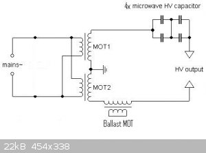
[Edited on 25-12-2014 by wish i had a kraken!!!]
|
|
|
jock88
National Hazard
Posts: 505
Registered: 13-12-2012
Member Is Offline
Mood: No Mood
|
|
Remember that MOT's have a small amount of primary winding turns. If you operate the circuit above and draw no current from the output, the MOT's will
get hot due to the excessive magnetizing current drawn.
Things are not so bad when drawing a sensible current from the secondaries.
|
|
|
wish i had a kraken!!!
Hazard to Others
Posts: 157
Registered: 22-3-2012
Member Is Offline
Mood: No Mood
|
|
my Problem is that MOTs get hot when I use to make Plasma in a vacuum chamber , after 3 minutes they get HOT , I fear that I may kill them.
|
|
|
franklyn
International Hazard
Posts: 3026
Registered: 30-5-2006
Location: Da Big Apple
Member Is Offline
Mood: No Mood
|
|
Heat will kill your components when operated above rated temperature limits. The ' ballast ' MOT , I see has secondary winding connected as an
inductive choke and you are running twice the rated voltage through it. Reactance is insufficient to drop that voltage. The components over heat from
excess power. The in series MOTs produce full power all the time whether it is used or not. Increase the load ( your plasma setup ) to consume it , or
use the primary of the ' ballast ' to run a heater. The voltage you output there will also be twice the rating. A lamp dimmer in series with that
heater and ' ballast ' primary can adjust diversion of power from the main circuit.
.
|
|
|
| Pages:
1
2 |


