| Pages:
1
..
3
4
5
6 |
radiance88
Hazard to Self

Posts: 64
Registered: 18-12-2014
Location: underground volcano fortress
Member Is Offline
Mood: a little less evil than usual
|
|
Quote: Originally posted by WGTR  |
Both readings are near the bottom of their respective scales, and the accuracy may be rather poor at that point. What happens if you unplug the
transformer with the meter still connected in the circuit? Do the values change, or stay where they are?
I have, on more than one occasion, accidentally tried to measure voltage while the meter was set up to measure current. What happens at this point,
is that a lot of current will try to flow through the meter. This blows the protection fuse inside the meter. The voltage measurements are
still good, but the meter will not measure current until the fuse is replaced. Sometimes, there is an extra fuse inside the cover, because everyone
makes this mistake at some point. Just popping the cover off the back of the meter and looking at the fuse should tell you if this is the problem.
Heck, you can even take the fuse out and check it with your ohmmeter. It should be almost 0 ohms.
The only other thing I can think of, is that perhaps one-half of the bridge circuit is not making a good connection. You could try measuring DC
current to see if you get a stable reading.
[Edited on 2-9-2015 by WGTR] |
I'm almost completely certain that the unit is defective. When I unplug the transformer while keeping the meter connected, it drops down to zero like
it should. The conversion factor isn't even correct between milliamps and microamps - those are separated by a factor of a thousand, but according to
my multimeter darn near everything measured via the millamp setting is reflected just by a single decimal point nudge to the right with the same
number using the microamp setting. I've built several different circuits with different values of resistance and it never even comes close.. Not to
even the right decimal point according to the correct computation that Ohm's law gives me.
The funny thing is, I bought this thing not knowing a single thing on how to use it. Now that I've used it frequently, testing different things, I'm
not as ignorant anymore and at least have a solid idea as to what figures it should give me. It's been almost a month now though, so I doubt the store
will give me a replacement. Ahh the cost of my ignorance.
I checked the fuses and they are both fine. Neither of them blew on me. I see a few reviews on amazon regarding this tool, and seeing some of the
defective unit complaints, I think it's feasible that I have been given a dud somehow.
I'm heading to the store first thing tomorrow and going to see if they can give me a replacement, if not fix it. This MM is only 50 USD, but cost me
100 on the other side of the world.
[Edited on 10-2-2015 by radiance88]
|
|
|
radiance88
Hazard to Self
Posts: 64
Registered: 18-12-2014
Location: underground volcano fortress
Member Is Offline
Mood: a little less evil than usual
|
|
I took the multimeter to the store with my breadboard setup, and slowly explained to the staff the the DMM wasn't reading my amps properly. I had to
teach them about Ohm's Law (lol) and then finally after a bunch of wasted time on both ends, they finally gave me a refund. I didn't exactly want a
refund, but they didn't have any other medium-price DMM with autoranging and ability to measure temperature.
They wanted me to upgrade to a Fluke, but I wasn't all that keen on spending half my month's salary all on a single DMM.
I hoofed my way all around town and couldn't find anything decent. So now I'm just a tad bit sad as I've gotten quite used to having it on hand 24/7.
I feel naked.. and alone, not having her by my side.
Does anyone have a recommendation for a medium-price DMM (up to $100 USD) that I could buy online? I'm tired of the jacked-up local prices and the
hassle of trying to find something that most stores around here don't have.
|
|
|
Sulaiman
International Hazard
Posts: 3555
Registered: 8-2-2015
Location: 3rd rock from the sun
Member Is Offline
|
|
I use Fluke etc. for work,
but at home I use one of those super cheap (£2.99) DMM a lot
and a £9.99 DMM that has a serial interface.
Both have a temperature range.
With modern components the accuracy and reliability of these cheap DMMs is pretty good.
e.g. my £2.99 DMM when checked against a calibrated Fluke DMM was within it's specified accuracy tolerance.
Personally I'd rather have two (or more) cheap DMM than one expensive DMM.
My only concern is with higher voltages,
I literally exploded one of the cheap DMMs because I (stupidly) assumed that since there was a 2000V dc range,
the meter could measure up to 2000 V ... WRONG !
I trust them up to 240 Vac or about 500 V dc ... after that I'd be very careful, especially in a high power or energy circuit.
P.S. if you do buy an expensive DMM check how much the internal fuses cost to replace
... more than either of my cheap DMMs !
P.P.S. my Fluke uses 4x AA alkaline batteries and it EATS them
my cheap DMM uses a 9V battery and I forget when I last replaced it.
[Edited on 11-2-2015 by Sulaiman]
[Edited on 11-2-2015 by Sulaiman]
|
|
|
Fulmen
International Hazard
Posts: 1693
Registered: 24-9-2005
Member Is Offline
Mood: Bored
|
|
I agree, even cheap MMs work fine in my experience. I now have 3 (one fluke and two cheap ones) and wouldn't be without any of them, nice for
measuring both voltage and currents at the same time. If you find an affordable one with auto-range, go for it.
|
|
|
Magpie
lab constructor
Posts: 5939
Registered: 1-11-2003
Location: USA
Member Is Offline
Mood: Chemistry: the subtle science.
|
|
I have a cheap RadioShack multimeter that I bought ~10 years ago. It has a plug-in attachment for measuring current via clamp-on. It's OK except it
does not measure small resistances (0-1000Ω) accurately. For that I use my 45 year-old Heathkit multimeter which works just fine, but has no current
measuring capability. And it is big and clunky.
The single most important condition for a successful synthesis is good mixing - Nicodem
|
|
|
The Volatile Chemist
International Hazard
Posts: 1981
Registered: 22-3-2014
Location: 'Stil' in the lab...
Member Is Offline
Mood: Copious
|
|
I'd have a nice one to use, but I took my Dad's analog one apart, which ended up shattering the selection dial in it when I was 10....
Interesting side note, a 'dial' is an organic molecule containing two aldehyde groups.... 
|
|
|
WGTR
National Hazard
Posts: 971
Registered: 29-9-2013
Location: Online
Member Is Offline
Mood: Outline
|
|
| Quote: |
I want to thank you for helping me so far with my electronics projects. I'd also like to ask you for some advice (being that it probably isn't that
important enough to actually post about
Is "true rms" really important in a multimeter? I'm kind of going nuts here trying to find the right DMM for me but I'm not too sure what to look
for, and there are so many features, price points that it's kind of weighing on me heavily.
I just want to buy something that will work for my hobbyist stuff, but am not sure that it justifies spending $300 on it either..
|
You're welcome; no problem.
The answer to your question is subjective, and different people will have different opinions. My personal meter is a Fluke "true RMS" meter, but the
ones that I use at work are cheap, non-RMS types. "True RMS" capability only matters for AC voltages. It doesn't affect the DC ranges, normally. An
ordinary, non-"true RMS" meter assumes that the AC voltage is a sinusoid. It measures the peak (or average rectified) voltage, and applies a
correction factor to get RMS voltage. If the AC signal is a square wave, triangular wave, etc., then the correction factor that it uses will be wrong.
The measured voltage will then be slightly incorrect. A "true RMS" meter uses more complicated circuitry to get a more accurate measurement, even when
the AC waveform has an irregular shape.
A True RMS meter is useful when doing a lot of work with power line frequencies (50-60Hz), where the waveform may not be a sinusoid. It is not
important to me, because an oscilloscope is better for measuring AC voltages anyway. In my opinion, it is better to get a cheap meter and a good used
oscilloscope, rather than an expensive meter by itself.
The meter can be used to measure AC/DC current and voltage, resistance, and ideally capacitance and inductance. The oscilloscope can be used to
measure both AC and DC voltages and frequency. It has the bonus that most of them can display two or four channels at the same time. An oscilloscope
allows one to see the actual waveforms in a circuit, at two or four places at once.
I picked up an old Tektronix 547 oscilloscope, complete with the rolling cart, for $75. It was my first 'scope, and it still works today, although
barely. There are much better models and deals to be had. Ebay has good deals, and bad ones. I don't know if you have "Ham radio" in your country, but
if you do, local Hams can be very helpful with helping you find test equipment. Some may offer things for good deals, if you explain your situation
and interests. If you post this question again in the thread, others will have some more useful advice to add.
Personally, I think the three very basic pieces of test equipment to have are a basic multi-meter, an oscilloscope, and a function signal generator.
I sometimes make mistakes, so it is better for others to be able to see what I'm writing, to provide "peer review" you know?
If you don't mind, I'll post this PM in the thread.
|
|
|
aga
Forum Drunkard
Posts: 7030
Registered: 25-3-2014
Member Is Offline
|
|
When it comes to Tools, it always pays to get a Good one.
Bad tools cause all sorts of problems - even a Master Craftsman will struggle to make an artwork out of dog-turds.
For the price, a second hand Fluke 15B would be a good choice and last you decades.
|
|
|
jsc
Hazard to Self
Posts: 65
Registered: 16-3-2011
Member Is Offline
Mood: No Mood
|
|
Your multimeter was probably working correctly. You were probably doing something wrong. In that situation the right thing to do is to test it on a
simple circuit, for example, 9v battery, resistor, LED. If you had put the meter in this circuit it probably would have shown the correct and expected
current flow. Note that an ampmeter has to be inline with the circuit. You don't just touch the leads to the posts like with a voltage reading.
Modern "leadless" solder is difficult to work with. If you can find old leaded solder at a flea market I recommend that. Breadboards are a preferable
alternative. Avoid soldering if at all possible.
Taking on a radio project is ambitious for a beginner and I would recommend starting off with much easier projects unless you have a definite and
specific need to do radio. Also, radio is kind of a specialized field. Most "inventor" and "self-help" electronics projects deal with control and
logic (turning stuff on and off), not radio.
I would not even attempt a radio project without a good quality LCR inductance meter. I use the DE-5000 LCR Meter which costs $140.
You cannot do radio projects on breadboards due to shielding and stray capacitance issues. Normally you do them what is called "dead bug" style.
Building a radio project out of a kit without understanding the theory of what is going on and just hoping to blindly duplicate someone else's design
is not a recipe for success. Also, radio kits tend to be very simplified designs that are defective in many respects and do not work very well. When
starting out, you want to be doing projects where the results are likely, definite and concrete.
If you are determined to do radio, I would recommend using Ronald Quan's book "Build Your Own Transistor Radios", which is light years ahead of
anything else when it comes to practical radio tutorials. His designs are REAL working designs, not joke kits that don't work 90% of the time.
To learn starting from the ground up I would recommend the book "Complete Electronics Self-Teaching Guide" by Earl Boysen. This book goes step-by-step
from the very beginning and teaches you all the basic stuff you need to know and how to use all the equipment. There are short exercises and problem
sets for each section to test your understanding.
If you work through the 500 pages of Boysen's book, the next step would be "Electronics for Inventors" by Paul Scherz. This book has 1000 pages. This
book goes into more practical details and outlines how to turn the theory and technique you learn in Boysen into real working projects that have a
practical benefit. If you work through both of these books thoroughly, you will have a good working knowledge of how to do electronics.
[Edited on 19-2-2015 by jsc]
[Edited on 19-2-2015 by jsc]
|
|
|
Chemosynthesis
International Hazard
Posts: 1071
Registered: 26-9-2013
Member Is Offline
Mood: No Mood
|
|
I wanted to extend a "thank you" for the book suggestions. Not only will they be helpful to me as well, but you gave me a great idea for a holiday
present for a friend I know in avionics who was kind of disgusted at the quality of radio kits.
|
|
|
xfusion44
Hazard to Others
Posts: 223
Registered: 6-8-2014
Location: Europe
Member Is Offline
Mood: Nostalgic
|
|
To all of you, who are beginners in electronics, I'd suggest you to buy a good, but not too expensive soldering iron (some people just like to
exaggerate with prices of equipment). For instance: 5$ soldering iron surely isn't very good for the job, but for 30-35$ you can get perfectly usable
soldering station. It doesn't heat up in 10 seconds, but it's more than enough for beginners. If you really need soldering iron, that heats up in 10s,
buy something for let's say up to 120$, but throwing money away on $500 Wellers is just nonsense. Personally I use cheap 30$ station, and at school I
use $300 Weller and other than heating-up time, there's no benefits for Weller. Almost all you pay that "extra" for, is brand. The same with
multimeters. I have 45$ Voltcraft multimeter, that has everything that beginner would ever need and more. Actually it's so good that I have the third
one now. First one died because I've been measuring 4kV with it and it was only meant for 250V (CAT2). And somewhere I even have a picture of it with
display reading of 2500V. Excellent multimeter and that's the proof, that you don't need to buy $100+ Flukes... Although Fluke is excellent brand, but
if you're beginner, you don't need it. $40 multimeter will measure all of the basic stuff, like voltage AC/DC, current AC/DC (uA, mA and A must be
separated), resistance, capacitor measurement, diode test, frequency, duty cycle, continuity test, non-contact voltage sensor (optionally). My VC175
is measuring up to 600V AC/DC (CAT3), which is very useful for higher voltages in switching circuits. Also, DO NOT buy cheap chinese multimeters as
they can cause fire and can be very dangerous when using them on mains voltage. When buying multimeter also be sure, that it has HRC (high rupture
capacity) fuses, which are much safer when it comes to overload.
[Edited on 27-2-2015 by xfusion44]
|
|
|
The Volatile Chemist
International Hazard
Posts: 1981
Registered: 22-3-2014
Location: 'Stil' in the lab...
Member Is Offline
Mood: Copious
|
|
Indeed. I suggest something better than the $10 one too, as something shorted out in mine, and I'm yet to get another soldering iron.
|
|
|
radiance88
Hazard to Self
Posts: 64
Registered: 18-12-2014
Location: underground volcano fortress
Member Is Offline
Mood: a little less evil than usual
|
|
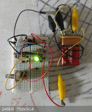
Okay.. so I'm really stumped here. I am using another multimeter here, and have a simple circuit - a 1000 ohm resistor inbetween the 12v and 0 leads
of my small transformer here. I have two wires connected in series with it which I use to measure my amperage.
No matter what I seem to do I can't ever get a good reading from it. Even when I hook up the leads from the DMM to it the DMM doesn't read anything
but but slowly trails off down into zero as if it weren't even connected. I should be getting theoretically 12 mV.
Anyone have any ideas?

|
|
|
WGTR
National Hazard
Posts: 971
Registered: 29-9-2013
Location: Online
Member Is Offline
Mood: Outline
|
|
I could be looking at it the wrong way, but it looks to me like the two red wires sticking in the air are both connected to the 0V side. There
shouldn't be any measurable voltage or current there, since they are shorted together on the proto board.
|
|
|
aga
Forum Drunkard
Posts: 7030
Registered: 25-3-2014
Member Is Offline
|
|
It does look that way.
On your breadboard, the connections are up/down for the middle two rows.
All of the others run left/right
Edit:
The holes in the breadboard in the photo are connected together like this :-
Central : all Xs are connected together, ditto all Ys
XY
XY
XY
All Others:
AAAAA BBBBB
CCCCC DDDDD
EEEEE FFFFF
They're like that so you can stick a DIL packaged chip in the middle and get to all the pins.
The up/down middle ones are like that so you can get power to all places easily.
[Edited on 28-3-2015 by aga]
|
|
|
The Volatile Chemist
International Hazard
Posts: 1981
Registered: 22-3-2014
Location: 'Stil' in the lab...
Member Is Offline
Mood: Copious
|
|
That's funny. That's the same mistake I made when I first tried to use a breadboard. Or is it Bredboard? I've seen both...
|
|
|
aga
Forum Drunkard
Posts: 7030
Registered: 25-3-2014
Member Is Offline
|
|
The Problem seems to be a basic misunderstanding of the Tools.
A simple circuit like a voltage source and a resistor cannot be this difficult.
Omit the Breadboard.
Use the twisting-together-of-wires method.
One of the wires from the transformer to one end of the resistor, twist together.
Ditto the other wire/the other end of the resistor.
Make sure there is a Voltage coming out of the transformer.
It will be AC not DC (set multimeter accordingly).
Oh dear.
To measure an AC Current you may need a different meter.
As you're just getting started, best use a DC source instead of an AC source.
First Project : build a DC voltage source.
You can just add a bridge rectifier to what you have : (search the page for Graetz bridge)
http://en.wikipedia.org/wiki/Rectifier
or use an old PC PSU instead (maybe cheaper)
http://www.instructables.com/id/How-To-Build-A-Power-Supply-...
|
|
|
m1tanker78
National Hazard
Posts: 685
Registered: 5-1-2011
Member Is Offline
Mood: No Mood
|
|
| Quote: Originally posted by radiance88 | [...]have a simple circuit - a 1000 ohm resistor inbetween the 12v and 0 leads of my small transformer here. I have two wires connected in series with
it which I use to measure my amperage.
No matter what I seem to do I can't ever get a good reading from it. Even when I hook up the leads from the DMM to it the DMM doesn't read anything
but but slowly trails off down into zero as if it weren't even connected. I should be getting theoretically 12 mV.
Anyone have any ideas?
|
12mV is too little for your meter to resolve IMO. Try using a 100 ohm shunt to put you in the 100+mV ballpark. My DMM picks up 53mV of stray AC before
zeroing without being connected to anything, for reference. AC (even switching DC for that matter) is kind of tricky to accurately measure. The
problem is exaggerated in the tens of mV range and below.
Since you have a breadboard, you can rig up a simple and cheap bridge rectifier with '1n400x' diodes and try different capacitors for different loads.
You can always simulate the circuit and then verify on the breadboard.
Chemical CURIOSITY KILLED THE CATalyst.
|
|
|
sodium_stearate
Hazard to Others
Posts: 255
Registered: 22-4-2011
Location: guard duty at the checkpoint
Member Is Offline
Mood: No mask.
|
|
If you don't already have some, I highly recommend
getting some test leads.
These are also called clip leads. They come in 2 basic styles.
One style has small "mini-grabber" spring-loaded hooks
that are very handy for accessing small spaces such as
transistor or integrated circuit leads or pins.
The other type have alligator clips on the ends.
Having a huge wad of clip leads handy always makes
testing easy.
Also, I recommend making up a set of special leads
for your multimeter that plug into the holes on a
solderless breadboard.
You can easily make up a set of these meter leads.
One end will have an insulated female plug to push the meter
probe into. Then have that connected a short length
of #24 gauge tinned single-strand insulated copper wire
(make one red, the other black). Then on the far ends
of those leads, strip off about .25 inch of insulation
so the lead can fit down in any of the breadboard holes.
This makes using your multimeter on a solderless breadboard
circuit easy, safe, reliable, and completely painless.
One other thing: Regardless of what else you are told,
using anything larger in diameter than 24 gauge wire
in the solderless breadboard holes will stretch the tiny
springs open inside the solderless connectors down inside
the holes. Using #22 gauge wire will do this.
Once those tiny spring-contacts get stretched and bent open,
they make loose and flakey connections. That then leads
to all sorts of highly irritating intermittent problems with
any circuit built on the board.
To keep your solderless board fresh and tight, use only
24 gauge tinned jumpers. (not bare copper because that
oxidizes quickly, leading to more flakey connections)
Also I think that you need to obtain a copy of the
rather ancient hardcover book titled
"The Boy Electrician" by Alfred P. Morgan.
That book is very useful and it explains everything from
the ground up. It's not just for young boys either.
There are many projects in it that any adult will
find challenging and educational.
[Edited on 21-4-2018 by sodium_stearate]
"Opportunity is missed by most people
because it is dressed in overalls and it
looks like work" T.A. Edison
|
|
|
mayko
International Hazard
Posts: 1218
Registered: 17-1-2013
Location: Carrboro, NC
Member Is Offline
Mood: anomalous (Euclid class)
|
|
for a long time, I had trouble soldering, even with a decent iron. In particular it was hard for me to keep the iron in contact with the component
long enough to heat and melt properly without slipping off, and to compensate I was applying unnecessary pressure, which was a bad habit. All these
problems went away when I used a chisel tip instead of the point type!
I dont't think that anyone has mentioned Forest Mims; here's a couple of his guides. I also have the Mims general electronics book but it's too large
to attach ... if there's interest i'll look into hosting or something.
Attachment: Forrest Mims-engineer's mini-notebook 555 timer circuits (radio shack electronics).pdf (2.8MB)
This file has been downloaded 291 times
Attachment: Forrest Mims-Engineer's Mini-Notebook Magnet And Sensor Projects (Radio Shack Electronics).pdf (4.2MB)
This file has been downloaded 306 times
My first 555 project was based on the LED flasher on p. 26 of the Mims 555 book, a simple blinker with adjustable strobe rate:
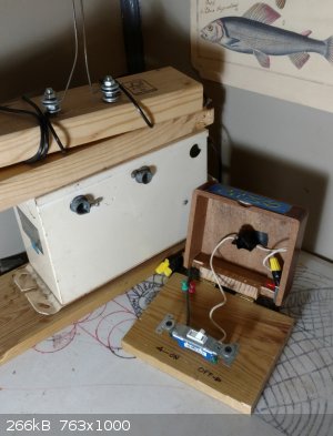
I've also wanted to do some beefier projects like Tesla coils. I've been lugging around an old neon sign transformer since I found it a few years ago;
only a recently did I get around to building a Jacob's Ladder with it. No mad science lab should be without!

al-khemie is not a terrorist organization
"Chemicals, chemicals... I need chemicals!" - George Hayduke
"Wubbalubba dub-dub!" - Rick Sanchez
|
|
|
sodium_stearate
Hazard to Others
Posts: 255
Registered: 22-4-2011
Location: guard duty at the checkpoint
Member Is Offline
Mood: No mask.
|
|
Another thing that is never taught in schools
is that regular "rosin core" solder does not have enough
flux to make it really flow properly.
This lack of flow is mostly responsible for
many of the troubles people always seem to have
with soldering.
A plain plumber's flux that contains zinc chloride is
very good for most soldering jobs such as twisted wires,
soldering wires to terminal lugs and jobs like that.
That type of flux is somewhat conductive and so should
be avoided when soldering on any sort of printed circuit
board. Using this flux on a PC board will conduct some
small current across traces. (It will be in the k-ohms region)
So, for close work such as PC boards, a special non-conductive
flux must be used. The non-conductive flux is nowhere
near as good of a flux as the zinc chloride flux is.
That is why I keep, and use both kinds of flux.
When a solder joint is made on bright metal and with
the proper amount of flux, the solder flows freely
just like water, and it thoroughly wicks into all
tiny crevices.
Without enough flux, the solder gets all sticky and muddy
and it leaves annoying peaks and it does not flow
very good at all.
"Opportunity is missed by most people
because it is dressed in overalls and it
looks like work" T.A. Edison
|
|
|
Sulaiman
International Hazard
Posts: 3555
Registered: 8-2-2015
Location: 3rd rock from the sun
Member Is Offline
|
|
+1 on the flux
For convenience I use a flux pen https://uk.rs-online.com/web/p/solder-fluxes/2513637/
I find it especially useful for smd as a little flux can be applied to the pads,
when allowed to evaporate for a few minutes it becomes sticky,
smd ICs can be tacked in place by pressing onto the sticky flux.
Even with added flux I use flux-cored solder (rosin has been discontinued for health reasons).
Lead-tin solder behaves much better than lead-free.
=================================
Regarding multimeters,
last year I bought an AN8002 multimeter that I am VERY pleased with,
others that I know bought the AN8008 and they are happy too.
https://www.ebay.co.uk/itm/Auto-Ranging-Digital-Multimeter-V...
CAUTION : Hobby Chemist, not Professional or even Amateur
|
|
|
DavidJR
National Hazard
Posts: 908
Registered: 1-1-2018
Location: Scotland
Member Is Offline
Mood: Tired
|
|
| Quote: Originally posted by Sulaiman | For convenience I use a flux pen https://uk.rs-online.com/web/p/solder-fluxes/2513637/
I find it especially useful for smd as a little flux can be applied to the pads,
when allowed to evaporate for a few minutes it becomes sticky,
smd ICs can be tacked in place by pressing onto the sticky flux.
Even with added flux I use flux-cored solder (rosin has been discontinued for health reasons).
Lead-tin solder behaves much better than lead-free.
|
I don't think it's entirely accurate to say 'rosin has been discontinued'. Sure, synthetic fluxes are increasingly common, but it's still easy to buy
flux-cored solder as well as solder paste containing rosin/colophony.
Also, some of the newer lead-free alloys are not too terrible. Still, nothing beats 63/37 tin/lead (eutectic) solder.
|
|
|
yobbo II
National Hazard
Posts: 709
Registered: 28-3-2016
Member Is Offline
Mood: No Mood
|
|
How new and shiny your components and wires are will dictate how much solder and how aggressive the solder needs to be.
Brand new components that are clean and unhandled need very little. Old stuff that has been lying around for years needs very aggressive solder and
lots of it. Maybe even clean with sandpaper ro steel wool.
|
|
|
sodium_stearate
Hazard to Others
Posts: 255
Registered: 22-4-2011
Location: guard duty at the checkpoint
Member Is Offline
Mood: No mask.
|
|
The basic idea is to scrape off the oxidation layer
and get down to shiny copper. Solder will not
adhere to an oxide layer.
Also, I've never used the "new" "lead-free" solder
and never intend to use it. Everything I've heard
about it indicates that it's really lousy.
"Opportunity is missed by most people
because it is dressed in overalls and it
looks like work" T.A. Edison
|
|
|
| Pages:
1
..
3
4
5
6 |


