| Pages:
1
2 |
Metacelsus
International Hazard

Posts: 2531
Registered: 26-12-2012
Location: Boston, MA
Member Is Offline
Mood: Double, double, toil and trouble
|
|
Building a Raman spectroscope: my attempt
I am going to build a Raman spectroscope over the next few months. This thread is to document my work; I'm starting a new thread so as not to clutter
existing ones.
First Steps:
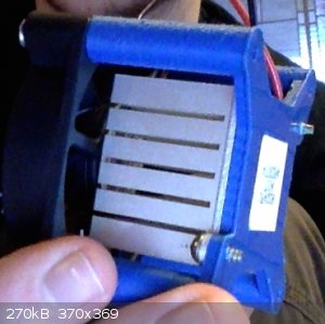
I've bought a Toshiba TCD1304AP CCD detector, a Peltier cooler, a Nucleo F401RE microcontroller, and a power supply. I'm waiting for my laser (25 mW,
532 nM) to arrive. Currently, I'm working on the optics and electronics design (using Eagle to lay out the PCBs). I should be done with the designing
by the end of the week.
|
|
|
aga
Forum Drunkard
Posts: 7030
Registered: 25-3-2014
Member Is Offline
|
|
Do you have a Plan of how you will construct this ?
What are you going to use to filter out the excitation laser's wavelength ?
|
|
|
Zombie
Forum Hillbilly
Posts: 1700
Registered: 13-1-2015
Location: Florida PanHandle
Member Is Offline
Mood: I just don't know...
|
|
Anxious to see what you develop.
They tried to have me "put to sleep" so I came back to return the favor.
Zom.
|
|
|
Metacelsus
International Hazard
Posts: 2531
Registered: 26-12-2012
Location: Boston, MA
Member Is Offline
Mood: Double, double, toil and trouble
|
|
Yes, I have a plan. This is a school project (the school said I could do a project of my choice), but I will be doing it at home. I'll most likely use
an edge filter for filtering out the laser wavelength. I also might try blocking it with a thin mirror after it comes out of the diffraction grating.
I am going to use OSHpark for the PCBs, as I can't etch double-layered PCBs very well at home.
The laser arrived yesterday, by the way.
|
|
|
blogfast25
International Hazard
Posts: 10562
Registered: 3-2-2008
Location: Neverland
Member Is Offline
Mood: No Mood
|
|
A diagram would be useful here.
|
|
|
aga
Forum Drunkard
Posts: 7030
Registered: 25-3-2014
Member Is Offline
|
|
Quote: Originally posted by Cheddite Cheese  | | use an edge filter for filtering out the laser wavelength. I also might try blocking it with a thin mirror after it comes out of the diffraction
grating. |
It will be very interesting to see what results you get with each of those methods, either singly or together.
Please post details of the filter (and where to get one) .
I use a strip of pcb and selloptape. Line the two transparencies up with the strip of pcb off to one edge and tape them to the strip.
When you put your board in there, use a couple more tabs of sellotape to hold the thing in place.
If that mob do them cheap enough, may as well save yourself the bother tho.
Woohoo !
Can't wait to see some results.
|
|
|
Metacelsus
International Hazard
Posts: 2531
Registered: 26-12-2012
Location: Boston, MA
Member Is Offline
Mood: Double, double, toil and trouble
|
|
Update
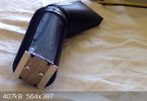
Work has been going slowly, but steadily (my time is split between this and the TEMPO project). After a bit of trouble with the 3D printer, I managed
to print all the parts for the spectroscope portion (I'll build this section before the Raman scattering one).
On another note, I learned not to trust sketchy $4.95 ATX power supplies from the surplus store. Of two I bought, one did nothing, and one made a
small explosion (a bad capacitor, I think).
|
|
|
Steam
Hazard to Others
Posts: 238
Registered: 25-3-2014
Location: Minnesota
Member Is Offline
Mood: Triple Point
|
|
I am very interested, how do you plan to collect/ analyze your data?
I am attempting to build my own raman spectrometer.
DISCLAIMER: The information in this post is provided for general informational purposes only and may not reflect the current law in your jurisdiction.
No information contained in this post should be construed as legal advice from the individual author, nor is it intended to be a substitute for legal
counsel on any subject matter. No reader of this post should act or refrain from acting on the basis of any information included in, or accessible
through, this post without seeking the appropriate legal or other professional advice on the particular facts and circumstances at issue from a lawyer
licensed in the recipient’s state, country or other appropriate licensing jurisdiction.
|
|
|
Metacelsus
International Hazard
Posts: 2531
Registered: 26-12-2012
Location: Boston, MA
Member Is Offline
Mood: Double, double, toil and trouble
|
|
I'll use a CCD hooked up to a STM Nucleo board, with a USB connection to a computer.
|
|
|
byko3y
National Hazard
Posts: 721
Registered: 16-3-2015
Member Is Offline
Mood: dooM
|
|
Will any window, lense and diffraction grating make noise in the spectr? I would be glad to make my own IR or Raman spectrometer, but the restriction
on materials holds me back. Otherwise Raman spectrometer could be really cheap.
|
|
|
Metacelsus
International Hazard
Posts: 2531
Registered: 26-12-2012
Location: Boston, MA
Member Is Offline
Mood: Double, double, toil and trouble
|
|
I'm not sure how much noise will be present. Theoretically, my spectroscope (a Littrow configuration) should be able to get down to 1 nm resolution.
However, this requires a very small slit width. If the signal-to-noise ratio is too small, I may need to increase the slit width to let more light in,
thus sacrificing resolution.
|
|
|
smaerd
International Hazard
Posts: 1262
Registered: 23-1-2010
Member Is Offline
Mood: hmm...
|
|
Cheddite did you hook up a ghost load on the ATX supply which did nothing? Often times they won't do anything unless one of their power lines atleast
has a small resistive load IE a series resistor & LED or something.
|
|
|
Metacelsus
International Hazard
Posts: 2531
Registered: 26-12-2012
Location: Boston, MA
Member Is Offline
Mood: Double, double, toil and trouble
|
|
Yes, I did.
|
|
|
IrC
International Hazard
Posts: 2710
Registered: 7-3-2005
Location: Eureka
Member Is Offline
Mood: Discovering
|
|
I have been working on several variations of Lock-In Amplifiers since it is possible to detect signals buried in noise which can be orders of
magnitude greater. Doing some searching as it relates to this area I found a very good paper that I thought I should post here. Have you given any
thought to this approach? This thesis appears to be very applicable to your project.
Attachment: A Lock-In Amplifier for Fluorescent Light Detection.pdf (3.9MB)
This file has been downloaded 753 times
"Science is the belief in the ignorance of the experts" Richard Feynman
|
|
|
Marvin
National Hazard
Posts: 995
Registered: 13-10-2002
Member Is Offline
Mood: No Mood
|
|
A lock in amplifier solves a different problem. For a Raman signal on a CCD the thing to do is integrate and background subtract. Frames as long as
possible as often as possible and just add the signal together. SNR will improve with the square root of the number of frames.
|
|
|
Metacelsus
International Hazard
Posts: 2531
Registered: 26-12-2012
Location: Boston, MA
Member Is Offline
Mood: Double, double, toil and trouble
|
|
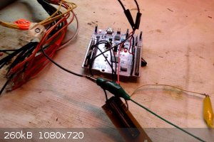
I got my CCD working with the Nucleo, finally! Spectra (and more details) are soon to come.
The oscilloscope picture is the CCD partially blocked with a finger.
(Pictures of oscilloscopes, or at least 1950-s era ones, apparently don't show up very well: an interesting effect of the speed of the eye being
slower than the speed of the camera.)
[Edited on 17-5-2015 by Cheddite Cheese]
|
|
|
smaerd
International Hazard
Posts: 1262
Registered: 23-1-2010
Member Is Offline
Mood: hmm...
|
|
*watches eagerly*
This looks like a really low cost build. I'm really excited to see how you build your optics path. I like your approach so far. I may follow in your
foot steps after I wrap up two of these projects and you have yourself some success.
edit - I really wish there was a subforum for building scientific instruments/tools. There's so much ingenuity on here.
[Edited on 17-5-2015 by smaerd]
|
|
|
aga
Forum Drunkard
Posts: 7030
Registered: 25-3-2014
Member Is Offline
|
|
The hell with a subforum - keep it going !
I also eagerly await an outcome.
|
|
|
Metacelsus
International Hazard
Posts: 2531
Registered: 26-12-2012
Location: Boston, MA
Member Is Offline
Mood: Double, double, toil and trouble
|
|
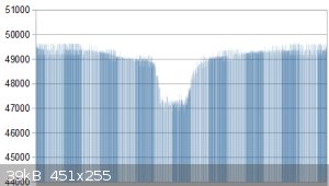
I've set up a program to save the CCD data on my computer; here is a preliminary example of the CCD being physically blocked.
|
|
|
smaerd
International Hazard
Posts: 1262
Registered: 23-1-2010
Member Is Offline
Mood: hmm...
|
|
Looking good! How are you talking to your microcontroller?
|
|
|
Metacelsus
International Hazard
Posts: 2531
Registered: 26-12-2012
Location: Boston, MA
Member Is Offline
Mood: Double, double, toil and trouble
|
|
I'm emulating a serial port over USB. (virtual port com3)
|
|
|
smaerd
International Hazard
Posts: 1262
Registered: 23-1-2010
Member Is Offline
Mood: hmm...
|
|
That's an interesting approach. I always used the RXTX libraries with JAVA which is pretty limited, but its cross-platform, and pretty easy once you
get the hang of it. The nice part of it is it lets you manipulate and display the data live (RAM permitting), gives you access to a UI if you want to
perform tasks like background subtract or whatever. If you choose to go that route let me know and I can set you up with a lot of code that will save
you tons of time.
Looks great though I check this thread probably five times a day.
|
|
|
Metacelsus
International Hazard
Posts: 2531
Registered: 26-12-2012
Location: Boston, MA
Member Is Offline
Mood: Double, double, toil and trouble
|
|
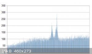
First Spectrum (not Raman, though)
This is of a red-orange laser diode:
Average of 8 scans, integration time 10 ms each. (I've found that more scans are better than longer integration times.)
I still need to calibrate the spectroscope to convert pixel number into wavelength, not to mention building the Raman scattering portion.
[Edited on 21-5-2015 by Cheddite Cheese]
|
|
|
aga
Forum Drunkard
Posts: 7030
Registered: 25-3-2014
Member Is Offline
|
|
The spectrometer is a huge part of the story, and both smaerd and yourself are well on your way.
I feel a Tricorder bashing it's way into existence.
[Edited on 21-5-2015 by aga]
|
|
|
m1tanker78
National Hazard
Posts: 685
Registered: 5-1-2011
Member Is Offline
Mood: No Mood
|
|
Nice job so far Cheddite. What type/resolution ADC are you using?
Chemical CURIOSITY KILLED THE CATalyst.
|
|
|
| Pages:
1
2 |


