First attempt at DIY Raman Spectrometry
For the past couple weeks I have been working on my (super-budget) Raman Spectrometer. Last night I finally (maybe) got a spectral image. First let me
talk about my set up. My goal is to make a handheld Raman spectrometer so I can analyze samples while I am out in the field. Eventually I wish to
build something similar to this: http://bwtek.com/products/nanoram/
This is the fist time I have built something like this and I do not know much about the process of actually processing digital data, but it will be a
learning experience I guess.
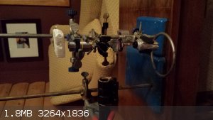
In my spectrometer I am using a 532 nm green laser pointer with 5mW of output power. The light travels to a 50/50 beam splitter. My beam then travels
up to a microscope objective and focused on a sample. In my first test this was Polystyrene foam. The Raman signal travels back through the objective
lens through the beam splitter again and into a 550 nm longpass filter form Throbs. The raman signal then travels though a small gemology diffraction
grating spectrometer which I picked up on eBay for about $30. Underneath the spectrometer I placed my phone (Samsung galaxy S3).
With the lights turned off I then took several spectra photos. Each of the photos were taken with ISO 1600 focused at inf and a 60 second exposure.
The first one with light shining down from above the longpass filter. I think some light leaked by the filter because I was not holding the led
flashlight directly above the spectroscope.
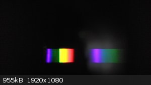
As you can see though there is a a sharp intensity drop at at about 550 nm beaning that the filter was working. I do not know why there is a second
image to the right of the spectrum but I expect it was because I was not holding the flashlight directly vertical to the spectrometer.
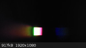
The next image I took with the flashlight directly above the objective. I got an overexposed image because the light coming back was far too intense,
but again there is a nice sharp cut off if it wasn't for the glair.
It was then time to take the image of the polystyrene. With the same camera settings and conditions I turned on the laser. At first I thought that I
wasn't getting any image, but after a minute I found this on my camera.
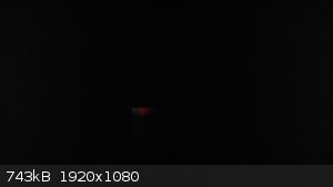
It is incredibly weak and there are no well defined peaks but there is something there. I am going to put my images through photoshop and see if I can
figure out what frequencies the image is displaying and see if it resembles anything close to polystyrene.
DISCLAIMER: The information in this post is provided for general informational purposes only and may not reflect the current law in your jurisdiction.
No information contained in this post should be construed as legal advice from the individual author, nor is it intended to be a substitute for legal
counsel on any subject matter. No reader of this post should act or refrain from acting on the basis of any information included in, or accessible
through, this post without seeking the appropriate legal or other professional advice on the particular facts and circumstances at issue from a lawyer
licensed in the recipient’s state, country or other appropriate licensing jurisdiction.
|


