smaerd
International Hazard

Posts: 1262
Registered: 23-1-2010
Member Is Offline
Mood: hmm...
|
|
Lithography/Lab On a Chip for the Masses
So the time has come to unveil my latest project which I dubbed as "top-secret"  . My project is based off of one publication. Namely, . My project is based off of one publication. Namely,
"Foil assisted replica molding for fabrication of microfluidic devices and their application in vitro", Issac J. Micheal, Aditya J. Vidyasagar, Kiran
Kumar Bokara, Naveen Kumar Mekala,Amit Asthana and Ch Mohan Rao. DOI: 10.1039/c4lc00659c.
I chose to do this project to honor an argument I had with a friend of mine a few years back. I said "Lab on a chip technology could never replace
current methods of synthesis/purification". I later changed my mind after researching the advantages and in true test of scientific rigor, have been
converted.
Many lithographic techniques utilize expensive chemical resists, etc. The principle behind this type of lithography is incredibly simple, and green
(aka not much waste, so doable at home).
An X-Y plotter device drives a ball point pen over aluminum foil. The aluminum foil gets a dent in the shape of the pattern. A silicon based elastomer
(PDMS used in solar cell encasing, etc) can then use this imprint as a mold to create microfluidics or lab on a chip projects.
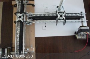
Mechanics -
My design utilizes two stepper motors with 1.7* steps on a belt drive. The mechanics are built from actobiotics parts with the exception of the wheels
and sheet of acrylic used on the one stepper. An arduino and L293D motor drive shield run the electronics and talk to the computer. (The images you
see being drawn on paper are not the current state of the instrument, it is far more reliable now)
So where do the images come from? They come from a computer.
Scheme/image -
The soft-ware reads a "scheme". Schemes are *.bmp images, which a user creates in whatever image editting soft-ware they want/have. The outlines must
be 1 pixel wide at any dimension. At any given pixel there can be only 2 adjacent pixels (think of this as a 1 dimensional representation). Each color
in the image specifies a separate drawing routine. So in cases where a user needs a 3-Way intersection they simply have to draw a different color for
the intersection. Pictured below is an example scheme:

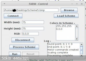
Soft-ware/How it currently works -
The soft-ware loads the image. Then finds any point on a specified line according to a user specified color. Then it traverses this line (very easy to
do in polar coordinates) to find an end point. Then it creates a list of condensed commands retraversing the line to the next end point to give to the
microcontroller. The algorithm can handle looping type schemes without issue(such as the one shown here and the start/end point in the software screen
shot below)
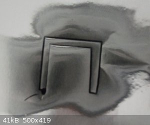
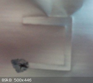
The microcontroller computes 20x commands then asks for more from the soft-ware until the scheme has been completely processed/drawn. Below are two
example results (positive side and negative side), please ignore the creases I made by handling the scrap of foil carelessly, this run was only for a
proof of concept.
--------------------------
Where am I at now? I have reliable drawing of linear shapes, curves are "okay" but could use a little work. Curves will be improved once I find a
better means to hold the pen rather then a "grip clip" (notice how there is some lee-way for a rotation using this kind of clip). I want to implement
a few more features (such as a solenoid to press the pen springload mechanism up/down so multiple drawings can be automated), and fine tune some small
things. I haven't run the motors in half or quarter steps yet to really tune the resolution. I will once a few other things are worked out (again it's
the physical parts of the projects/lack of tools that hold me back).
I hope this idea helps push lab on a chip experiments at home forward. I personally found most current DIY lithography techniques, cumbersome, not
reproduceable, not too mention expensive. The joy of "true" micro scale chemistry is that there is limited waste, and the field is brand spanking new
for innovation. Many of my ideas need lab on a chip scale for true control and laminar flow.
[Edited on 27-5-2015 by smaerd]
|
|
|
Harristotle
Hazard to Others
Posts: 138
Registered: 30-10-2011
Location: Tinkerville
Member Is Offline
Mood: I tink therefore I am
|
|
microfluidics
That is a good idea Smaerd.
I quite like the approach of drawing the design in inkscape or some similar, scaling it to the size you want, and then printing it to toner transfer
paper or if you are exceptionally cheap, glossy advertising brochure paper.
Next you iron it on to a piece of printed circuit board, with an 80 micron thick layer of copper. Remove the paper with hot water + a drop of
detergent.
Etch in ammonium persulfate, or just as good copper chloride/weak H2SO4, with strong stirring, and 1 drop of detergent (to stop bubble formation on
the suface of the board).
After that, just pour your PDMS over the top of the board and allow to cure. Drill the ports into the chip, activate a glass slide in H2SO4/H20 (1-2
seconds) then press the chip to it, leaving it to bond.
I have made a couple like this, and they worked, but my technique wasn't great. I always wanted to get back to it, maybe get a kid onto it as a
science project. I am delayed until I find a safer replacement to the pirrhana !
For an overview, check out the toner transfer method of making PCBs.
I know of one research lab using this techniques to make microfluidic chips.
Have fun now!
H.
|
|
|
smaerd
International Hazard
Posts: 1262
Registered: 23-1-2010
Member Is Offline
Mood: hmm...
|
|
Harristotle - I had actually entertained doing the lithography that way. It's just a lot of effort and requires a lot of chemicals. I do like just
printing it out and etching, it seems like a very reproducible and accessible way to create them once the technique is learned. The caveat is, it
requires a lot of chemicals and is pretty expensive, The nice thing about that method is that the mold is reuseable.
In the case of the project I'm working on, it only requires aluminum foil. Which is very cheap. The method is also rapid, One could go from design to
mold in 2 or some odd minutes without a good deal of chemical waste. Entry cost for a device like this is around 200$ USD, and there are kits for
these. MakerBot has one, I just wanted to build my one for cheaper and to suit my needs specifically. They essentially operate on the old school XY
Plotters that used to accompany analytical instruments amongst other things before the advent of printers.
Yes Pirhana is a bit of a concern, I worked with it everyday last summer. Although it has a bad rap, I never had any issues with it. Would I work with
it at home though? Not likely. There are other ways to oxidize the surface of glass though. I believe it has been reported that doing the old solvent
cleaning, and following up with 30% hydrogen peroxide was sufficient but required slightly longer sitting times. I had a publication on this at some
point, but I forget where it went off too.
|
|
|
aga
Forum Drunkard
Posts: 7030
Registered: 25-3-2014
Member Is Offline
|
|
Wait a sec. You do what ?
Form a mould in Al foil then make a cast, then attach that to glass ?
Would not surface tension become a problem with micro-sized flow channels etc ?
[Edited on 1-6-2015 by aga]
|
|
|
aga
Forum Drunkard
Posts: 7030
Registered: 25-3-2014
Member Is Offline
|
|
Still in the dark, i just imagined a dremel in your YX (hopefully Z) plotter and two microscope slides being ground out in intricate shapes, then
clamped together to form micro labs.
|
|
|
smaerd
International Hazard
Posts: 1262
Registered: 23-1-2010
Member Is Offline
Mood: hmm...
|
|
Aga - Yes, you make a mold out of aluminum foil. You pour PDMS overtop of that mold. It sets, you remove it. Then you adhere the PDMS/polymer to a
glass surface.
I'm not sure what you're talking about with regards to surface tension though. Some microfluidics actually use the surface tension as a driving force
via capillary action I guess. I'll be using the syringe pump I made on low flow rates though.
Basically what you're referring too is a cheapy CNC machine. I don't know how that'd work, glass is pretty fragile. Maybe with the right bit and a
stream of water. I think most people who do things like that with glass use laser etching, could be wrong.
edit - also, all the Z I need is a solenoid, so it's pretty much X&Y.
[Edited on 1-6-2015 by smaerd]
|
|
|
aga
Forum Drunkard
Posts: 7030
Registered: 25-3-2014
Member Is Offline
|
|
So, forgive me for not getting it straight away, you're making a microscopic lab !
Amazing stuff !
How do you actually Use it, physically ?
[Edited on 1-6-2015 by aga]
|
|
|
smaerd
International Hazard
Posts: 1262
Registered: 23-1-2010
Member Is Offline
Mood: hmm...
|
|
Hey aga sorry for the delay in response I just got back to investing some more time into this project. So after the mold is created and the PDMS is
cast. I then can adhere (chemically) the PDMS to a glass surface, or physically by applying pressure in spots where the are no channels via paper
clips/binder clips whatever. Then experiments on this small scale can be conducted. Obviously things such as heating are difficult, so my experiments
will be isothermal but I have a few things I really want to try out that'll be secret until I do them. For proof of concept I'll probably just do some
color mixing stuff. I'm saying they will be secret because if two of the ideas work then I'll have to publish them. The more fun ones can be shared on
scimad  . .
I was able to suss out some of the errors in the apparatus. The timing belts I used really can't be crooked or too loose. I went through and did some
adjusting and things are coming out better. I also build a holder for the pen so it won't be as free to wiggle that seems to have helped a tiny bit.
The biggest source of error in making these drawings is if the pen is pressing too tightly onto the paper. It really screws up the step count so the
motors make whacky out of scale images. Over-all the drawings are reproducible and have no problem denting foil. So version 1.0 is complete.
Still some minor issues with curves. They come out a little lopsided. I think this will be the best I can get it for now. I could write curves to be
done via the two steppers being driven at once using the AccelStepper library and changing my motor command creating algorithm. I'm not sure if I will
go that far because most of my designs don't need high accuracy as far as curves go. I'll be posting some of the code up in a few days for anyone else
to use. I'll also outline the materials I used. Over-all it is a pretty simply thing and there's a million ways to attack it. So I doubt anyone will
be recreating this in exactitude.
|
|
|
smaerd
International Hazard
Posts: 1262
Registered: 23-1-2010
Member Is Offline
Mood: hmm...
|
|
So I haven't implemented dual layer functionality yet. What I mean is, resetting the pen when a new color is processed. I'll do that when I actually
need to use two or more colors. I switched over to half steps and now I'm getting about 0.90mm per pixel for either axis which is about all I need.
For now I'm happy with the way this functions. It should suit most of my needs for the near future.
So in true open source fashion here's the code -
I'll also include two example schemes in-case someone wants something to test.
Attachment: FARM.ino (5kB)
This file has been downloaded 1275 times
Attachment: FARMCmd.java (1kB)
This file has been downloaded 1183 times
Attachment: FARMmain.java (19kB)
This file has been downloaded 899 times
Attachment: Point2D.java (794B)
This file has been downloaded 1066 times
Attachment: Stepper.java (1kB)
This file has been downloaded 1072 times
 
You'll probably notice some sections are not 100% complete, and there is more that could be done. Again, when I update this(probably in a long while)
I'll add those functions. If you don't like my programming practice, I don't really care, there's a reason I'm an ex-computer science major gone to
chemistry .
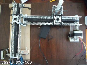
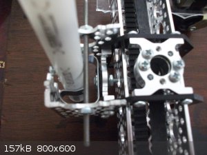
And two images, one of the over-all apparatus and one of the pen holder rig.
[Edited on 11-6-2015 by smaerd]
|
|
|
Texium
|
Thread Moved
22-11-2023 at 19:31 |
|


